
Hi-Fi LM3886 5.1 channel amplifier, with digital control - Power amplifiers
1 - Intro, 2 - The design, 3 - Pre-amplifier, 4 - Power Amplifiers, 5 - Power Supply, 6 - Grounding, 7 - Control - Hardware, 8 - Control - Software, 9 - Android App, 10 - Summary
Power amplifiers
On this page...
ESP LM3886 'gainclone' boards
The power amplifiers consist of five LM3886 chip amplifiers. The boards for all channels use Rod Elliott's ESP Project 19 - using two stereo boards for the front left and right, rear left and right, and a singular copied board I etched on my own for the centre channel. The performance of these is very good.
All amplifiers use the LM3886T or LM3886TF - the datasheet is here.
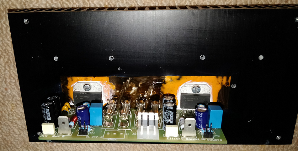
Front L/R amp - ESP P19 circuit board with 2x LM3886T, mounted to one of the side heatsinks
These chips claim 68W power output (for 4-ohm speakers at +/-28W). On my power supply of +/-35V, it will give 50W average output power for the more common 8-ohm speakers used for hi-fi and home cinema, and that's at an OK 0.1% distortion (not the crazy 1% to 10% distortion levels I sometimes see in datasheets!). With the decent heatsinks and large power supply I've integrated into the system, I'm quite sure it can reach 50W and stay running at 50W constantly and reliably. Into 4 ohms, I suspect it will give more, but probably distort earlier at the same sound pressure level. The general feedback I've read online is that this chip is not recommended for 4-ohm speakers, unless power supply is lowered appropriately.
50W may sound quite entry level when you see other amplifiers on sale - but it's quite plentiful. Power to SPL diminishes quickly and a 100W amplifier is only 20% louder before distortion, but requires bigger heatsinks, power supplies and a wallet. Bigger speakers are typically less efficient at the same power output too. For home cinema and the enjoyment of music listening, 50W per channel is enough. If you plan more serious work though, driving big speakers at party volumes in large halls or outdoor areas or a large private home cinema, then you will need more, but there's no reason you can't scale up what I've done, with say Class D amplifiers and a bigger PSU (perhaps switchmode).
Building amplifiers requires careful consideration around key areas:
- The amplifier design itself
- The PCB design and layout
- The power supply - see the next page
- The grounding - see the separate page for this
- Dealing with heat - see below
All these elements are important to making a great audio amplifier. I've let Texas Instruments and Rod Elliott sort out the design and board layout by purchasing a semiconductor chip-amp and Rod's boards directly. The power supply construction and grounding deserve their own pages!
Heatsinks
As for dealing with heat - 'Heatsinking' is very important and get the biggest heatsinks you can! I purchased some which were shipped from Australia, as they both looked good and were the perfect size and colour to affix to the sides of my 3U case. They keep the LM3886 sufficiently cool, but even they get a little warm on hotter days. Look for ones that have ribbed fins - these increase the surface area between the metal of the heatsink and the air around it, allowing the heatsink to dissipate more heat. The measure of performance of heatsinks is 'Thermal resistance', in °C/W. The lower, the better!
If you are stuck for room, or cost, use fans. There's a reason why any PC processor above 5W uses fans to dissipate heat - the more air passing past the heatsink, and the higher that air pressure greatly increases the amount of heat taking away from the heatsink and into the air. With amplifiers, fans are rarely used because they are less constrained by size and weight, and because fans also make a noise and we may want a quiet environment to enjoy our music in, or those quiet moments when watching certain films. I have used ESP project 42 on older builds though, with success.
Since the heatsinks at the side handle stereo amplifiers (that's two LM3886 chips), my boards use the standard LM3886 with the metal tab. This tab is connected to -Ve source, meaning on my split power supply, the potential difference between the tab and the heatsink itself (connected to the case, which is connected to earth), is 35 volts. I brought the Kapton tape (another DuPont invention) that Rod Elliott sells at the same price as the boards.
Connected properly to the heatsink, with the tape and insulted washer, the heat resistance between the chip and its heatsink is low, and the chip can run at a higher power without overheating. I used a thin layer of thermal compound each side of the tape to ensure good heat conductivity. Don't use silver-based compound like you would on PC CPUs. It conducts electricity as well as heat! We want to conduct heat only and not allow that amplifier tab at -35V short to ground.
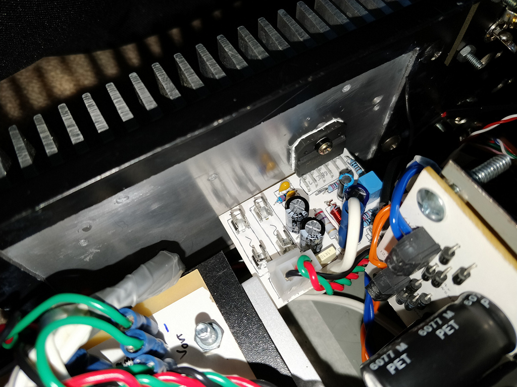
Centre channel amp - LM3886TF mounted to the rear heatsink
The LM3886TF is different. It's highly convenient because it is fully insulated already, you need only a thin layer of thermal compound. I choose this for my centre channel amplifier, as the size of the heatsink is bigger (for one chip) and because there is only one chip, any pressure on the board causing it to rotate around its fixing will mean it doesn't rotate beyond its insulation, causing it to short out. Remember the penalty for the convenience is you need a bigger heatsink to transmit as much heat that does get transferred from the chip as possible, because the inside of the chip will be hotter than the equivalent LM3886T at the same voltage/volume. I also used the LM3886TF for the rear channel amplifiers - this is because they will not be doing as much work as the other channels.
Never operate either amplifier without its heatsink by the way. It will overheat immediately. For build and testing, having a modular heatsink that can be detached from the main case is very handy for initial build, testing and servicing.
The PCBs and modifications
Using Rod's design is convenient, and the boards also come with spaces for fuses, meaning each amp is protected from meltdown in the event of a fault, and the other amplifiers and power supply are protected too from the excessive current draw when a fault does occur.
The boards also have 2.54mm headers for line inputs, spade terminals for speaker outputs and 3.96mm headers for power supply connectors. I used them all for convenience. When servicing, I can completely disconnect the wires from the PCB easily and detach the heatsink from the case. -This means I can easily remove the board, still attached to the heatsink without having to redo the fixing of the chips to the heatsink, meaning no messing around with thermal tape and compound.
Each of the amplifiers are treated individual, meaning they are all wired individually. This means I took to cutting the shared traces on Rod's board for the stereo modules (front and rear). On a stereo amplifier, you can get away with sharing the PSU and ground on the board, but for a five-channel amplifier, it is better to ground them all at the system ground (near PSU). For the power rails, it also meant I could use some thinner wire to each amplifier (more of a convenience as I already had some 5amp wire).
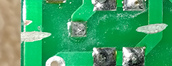
Cut traces on P19 PCB
Amongst cutting the power and ground between the stereo amplifiers on Rod's board, I also made some modifications to the board for grounding purposes. More on this in the next page.
Speaker Protection
As mentioned before - in its previous life, I did lose an amplifier caused by its heatsink tab shorting to the heatsink itself. The fuse blew and apart from the dead amplifier, the rest of the electronics survived but I also lost a speaker in the incident. It was a cheaper centre speaker, but I did not want this to happen to my more expensive front speakers, and more expensive all-round setup I now have.

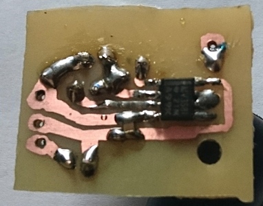
Speaker protection board
The solution is some speaker protection. This will detect DC on the output and short the speakers to ground immediately via relays. I'm hopeful this will be faster acting then fuses alone and offer some peace of mind should I really have a fault.
Again, Rod's design came to the rescue here. ESP Project 111 is ideal for this, and I used the DC detector, in combination with a comparator to provide a 'fault' signal to my central PIC itself. This is connected to the PIC's interrupt PIN, which will activate immediately to power off the relays upon detecting a fault.
Additionally, having relays on the speaker output means I can easily mute the amplifiers output after power on, and before powering off. This means I get no thumps or noises during the power cycle.
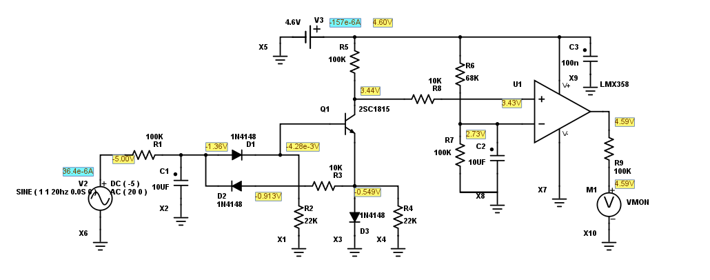
DC detector schematic, one channel. R1, C1, D1, D2 should be replicated for each channel.
Rod's improved project 111 detector circuit can be purchased outright and used in your design. For a 5-channel amplifier though, the DC detector part needs to be replicated. It does not have an ability to integrate with my own control PIC directly though, and not needing its additional functions (muting, temperature sensing, fan control), I decided not to use it entirely.
I simulated the output of it where it connects to his PIC microchip, which is somewhat analogue, but when simulating with a rail-to-rail op-amp as a comparator (LMV358), I got an output that would trigger (going low) at about +4V or -6V DC on the speaker output but hold high (at 5V) under normal conditions. I used LMV358 as I already had it (it is a dual op-amp, but the second one has been disabled). A normal op-amp (like uA741) will not be sufficient to swing to 5V or 0V, or operator at low voltage, however a dedicated comparator or a rail-to-rail op-amp will work.
Speaker protection board
The output of the DC detector going low can then drive an interrupt on change pin of my own PIC, where the muting relays are already connected. The use of the interrupt pin is important as I cannot make my own constantly poll an ADC (analogue to digital) conversion when it is requested to do other operations. After building it, I could test it works by connecting a 9V battery in both polarity orientations on the amplifier inputs to this board, and it would correctly send the comparator output low, causing my PIC to interrupt immediately, triggering the relays and displaying 'Fault' on the amplifier's character display. Do not do the 9V battery test with the amplifier connected though!
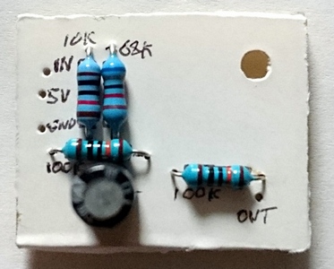
Rail-to-rail op-amp used as comparator
If you wanted to use Project 111 in its entirety, you could connect P111 to your amplifier PSU and use an opto-coupler on the RLY output to interface to your controller chip. Under normal conditions, that output would be high. If it is low, and if it is after the initial 10 second turn on delay (and powered on), this would indicate a fault has occurred. Or skip interfacing it to the controller chip anyway and let it run independently - P111 has an LED output itself (it blinks rapidly under fault).
Since the build, the amplifiers operate very well and reliably. The DC detector has not had any false positive faults, and I've not had any real faults to put it really to test!
That concludes details about my power-amplifier. Read on to the power supply and grounding, which are quintessential parts of a successful amplifier build!
References and more reading:
LM3886 Datasheet
ESP - Project 19 - Single Chip 50 Watt / 8 Ohm Power Amplifier
ESP - Project 111 - PIC Based Speaker Protection
Renesas
Electronics - Op-Amps, Comparator Circuit
Part Sim - Circuit Simulation Made Easy
Further pages here...