
Hi-Fi LM3886 5.1 channel amplifier, with digital control - Design
1 - Intro, 2 - The design, 3 - Pre-amplifier, 4 - Power Amplifiers, 5 - Power Supply, 6 - Grounding, 7 - Control - Hardware, 8 - Control - Software, 9 - Android App, 10 - Summary
Design
On this page...
My design has somewhat been based on what I had built already, other designs online, and many hours reading forum posts! It will help summarising it here though. Putting it altogether needs some sound design, and I learned through mistakes too!
Design success for me is good power, good sound, little hum, neatness and aesthetics. In my 2018 rebuild, I managed to address all of these goals to a stage that I'm very happy with. You could go further of course - I've seen plenty of impressive designs online addressing these areas to an impressive level! I did not want to go quite that far for the constraints of time and money, and the knowledge that I'm already probably out-doing a sub £1000 commercial design anyway!
Single unit
Originally, I had a separate preamp, phono preamp and power amp. This was easier to work with, but became cumbersome in size, and the amount of wires at the back.
In 2012 I torn down the preamp and combined it into the same case as the power amp, creating a new single PCB to contain all the PGA2310 volume controls (but without output buffers).
Combining both units into one meant the whole unit could be powered on as one, and the amount of wires around the back reduced considerably.
Layout
Layout was somewhat constrained to what I had before. This is the fourth large rebuild in the case I had used for the power amplifier, and as such it's already riddled with quite a few holes (some large), so making drastic changes I preferred not to do.
It is however a good enough layout, and it performs well. The principles I followed to satisfy my desired requirements were:
- Safety - Above everything else! This means a sturdy earth connection, shielded mains DC blocker and mains wires routed carefully inside
- Large heatsinks, external - this promotes excellent dissipation of heat for the power amplifiers
- Shielding - keeping the transformers within a shielded section reduces hum
- Use of space - by adding vertical panels inside both for shielding transformer interfere and becoming a useful place for mounting components
- Dedicated areas - mains voltages are only in the top left, low signal (preamplifier etc) is in the top right, transformers and digital in the centre and front, and amplifier mounted on all three sides. Dedicated areas like this reduces the length of wires and reduces audio circuits picking up interference from mains and digital circuits
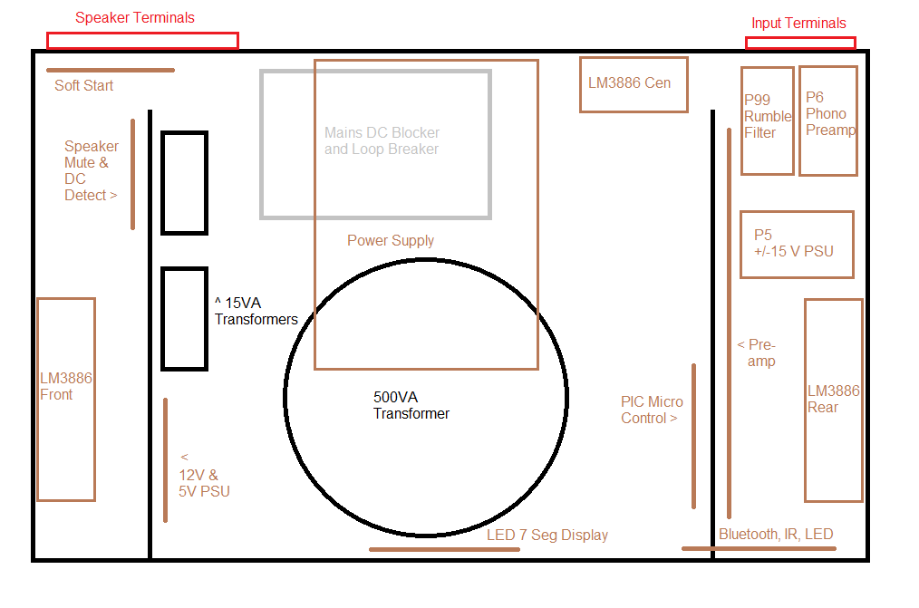
The layout (not to scale)
The layout is pretty good, but has some challenges:
- Everything is packed into one case - the quietest and best performing systems are in separate cases, in particular the PSU, preamp, phono and power amplifier. But I don't like lots of external boxes and wires.
- Some line level audio crosses the transformers - the most notorious is the cable from the pre-amp output on the right, to the front power amplifier input on the left.
- Mains and speaker connectors are close - not advised, but in practice hasn't caused a problem.
- Height - because of how much is packed it, a high 3U case is needed. To use that height, some circuits are mounted vertically, the PSU capacitor board is mounted above the DC blocker, and the side mounted heatsinks are high.
Update: I revised the utility power slightly in July 2022. I used a single 9VAC 15VA toroidal to power both relays (9V AC gives ~12V DC unregulated) and 5V digital electronics, instead of the separate 12V and 6V transformers. This improved efficiency slightly, along with removing Bluetooth support. The PSU board was located in the location of the removed toroidal, bottom left - layout diagram above is now the updated one.
Design problems led to hum, buzz and/or amplifier oscillation, causing a loss of performance and running hot. After hooking everything up, the design performed OK, but there was hum.
I read around various forums and web pages, and found the best advice for amplifier wiring and hum reduction is by Bonsai at hifisonix.com here. Thoroughly recommended reading!
This advice, and advice elsewhere led me to really think about the re-design to ensure hum-free performance, and with tweaks after the build, I did get there! To ensure that hum-free performance, I did the following:
- Revised the power supply - my new power supply PCB has plenty of capacitance, a CRC design to improve regulation a little, snubbers and most importantly, a 'T' based design for hooking up the grounds in the right order
- Tightly twisted all power supply and speaker cables
- Used a hum-breaking resistor at each amplifier input, as per hifisonix.com guide
- Every individual amplifier has its own ground, and power supply cables linking to the PSU 'T'
- A DC blocker is used to reduce transformer hum/growl, and therefore interference
- Redesigned PCBs to minimise ground path, loops and use a PCB star.
After these actions, hum is barely noticeable, and performance is superb. You can read more in the PSU and grounding pages.
Maintenance
In my previous designs, all components (PCBs and the like) I pretty much always soldered point to point. This does however give a lot of grief when doing maintenance, or during the testing and re-routing of cables. In the old design, to change things I'd often have to desolder and re-solder wires to move the PCBs enough to replace components, add features. Let me tell you it's not fun, and can result in the iron burning other wires, and the fingers or thumbs on more than one occasion!
Since I replaced many PCBs in the rebuild, I switched to using PCB connectors. The commonly named 'Dupont' connectors are handy for the majority of connections and fit 2.54mm spaced headers. All audio and control circuits were hooked up with these, and I brought a large pack of male headers for the PCBs, and various female connectors and a crimping tool for the wires.
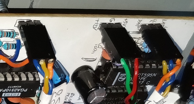
Dupont connectors on the preamp PCB
Yes, it does mean initial build is a little longer - but it has definitely saved me time overall. Being able to push fit all connections is very convenient. For the larger wires, I used 3.96mm Molex style connectors for the LM3886 power connections, and spade connectors for PSU and speaker connections, and screw down terminals for AC connections.
No wire is soldered at both ends, unless it is to and from the same PCB. Very few wires are soldered at one end. It's a massive benefit and I highly recommend it!
Aesthetics
Whilst I've been happy with the look of many of the projects I've built, this is my centre-piece, and is on proud display in the living room, alongside other tech!
I didn't want something 'DIY' looking - with bulky controls and hard to read LCD displays.
Since my wife and I only control it via the remote control anyway, there is simply no need for any controls on the front. It only needs to display responses (since the remote cannot do that).
The display of the responses needs to display an on/standby/mute status - done by a tri-colour (aka RGB) LED. But to display the active input and volume level, something that needs to be read is needed.
LCD displays are typical but mounting them so they look neat is a challenge, and when on they usually cannot be read without a backlight, and even with the backlight on the contrast is usually not good.
LED displays are better. Nowadays you can get OLED alternatives to the typical LCD displays, which look better, but I decided on 7-segment numerical displays. These can display some letters (in various character case), and enough for my need.
With all the output being LEDs - these are bright enough to shine through a tinted plastic front. I ordered a black translucent plastic front online, cut to size. It is dark enough to hide all deficiencies, effectively looking black, but the 7-segment characters and the tri-colour LED shine through fine. It also passes through infrared light so the IR sensor for the remote control is also hidden behind it.
The look was my wife's idea, and after my execution of it, the result is both unique, modern and pleasing. As an added benefit, no buttons or controls on the front meaning no one touches it (either by accident or through curiosity).
Further pages here...