
Hi-Fi LM3886 5.1 channel amplifier, with digital control - Grounding
1 - Intro, 2 - The design, 3 - Pre-amplifier, 4 - Power Amplifiers, 5 - Power Supply, 6 - Grounding, 7 - Control - Hardware, 8 - Control - Software, 9 - Android App, 10 - Summary
Grounding and reducing noise, hiss, hum and buzz
On this page...
Principles
Part of an amplifier design is focused on the circuit and PCB design itself to ensure good performance but throw it altogether in a case with a bad wiring scheme, and the performance will disappoint.
Over the years, I've rebuilt this amplifier several times and spent a great deal of time trying all sorts of schemes to try and get hum, buzz and hiss under control. Whilst I had managed to get it down to an acceptable level, as this rebuild really was the biggest rebuild the amplifier has seen, I definitely wanted to get noise under control this time.
With a multi-channel amplifier, grounding becomes even more harder to get right than a stereo amplifier (which in turn is harder to get right versus a Mono amplifier).
Whilst the rebuild was starting, I spent many hours reading websites and forums about grounding designs during my commute time to work, and bedtime reading!
The most useful guide was this one by Bonsai at hifisonix.com. It's a PDF but has some great tips and is recommended reading. The text below is my take on it though.
For my grounding scheme, I ended up using these principles:
- A loop breaker / ground lifter between safety earth and the amplifier ground was used
- Safety earth connected to the case/chassis at only one point. All other interconnects (such as phono sockets) isolated from the case.
- Separate Power and Audio/Signal grounds
- The use of star grounding - one for the preamp, and one system ground for the power amplifier
- Avoid loops
- Hum-breaking resistor at each amplifier
- Low resistance cables for all grounds
- Treating each single amplifier individually - i.e., not sharing the ground on a stereo amplifier PCB
- Tightly twisting wires, and keep them away from signal grounds
With these techniques used throughout, I did succeed to make a very quiet multi-channel amplifier. I have to put my ear right next to the speaker to hear a very low amount of hum and hiss. A very satisfactory result, as I cannot hear anything but silence when the soundtrack of a film or TV series has those tense moments of silence!
So, a little more on how I achieved the points above...
Loop breaker
I've always used these in my builds, but check they are legal where you live first. Safety is important - do not ever consider disconnecting the safety earth or lifting the amplifier ground completely from the safety earth and isolating it. Why? Safety earth is there to protect you, and others who use your equipment. A fault could be a mains cable breaking free, or moved and squashed by another component, or a faulty transformer, or mounting of sockets, fuses, the transformer itself coming loose etc. If you construct the equipment well, the chances of it happening are low - but it's never 'never' going to happen, so protection is needed, and usually a legal requirement.
This extends to ensuring the ground of the amplifier PSU itself is connected to the safety earth. If it is not, a fault of a mains wire breaking free and touching a PCB, or signal/power ground itself would not trip the safety earth breaker, but you or someone might walk other and touch the equipment, wondering why it's not working, and get electrocuted.
Connecting the safety earth directly to the power ground in the amplifier may result in hum though - typically when there is another piece of equipment where these two are connected together. Note: this is less of a problem nowadays as a lot of modern TVs, Blu-ray players, mini PCs, consoles are double insulated and have a two-pin mains plug either on the equipment itself or external PSU brick - so consider if it is necessary.
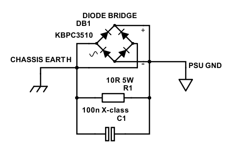
Safety ground schematic
My loop breaker was installed in the same metal box as my DC blocker (see PSU page), using a KBPC3510 35A bridge rectifier to isolate the ground whilst allowing very high fault voltages/currents to pass, with a 10 Ω resistor to maintain the connection, whilst reducing hum inducing voltages significantly. The capacitor allows HF radio interference to still short to chassis earth. This is per Rod's article on ESP 'Earthing Your Hi-Fi', which has been researched well and I've trusted for 18 years!
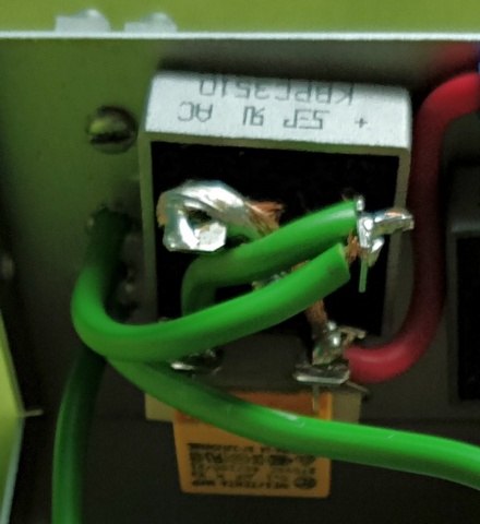
Safety ground connected inside my DC blocker case
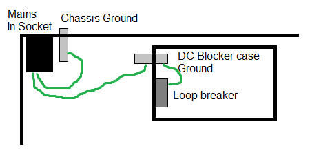
Chassis connection - Safety earth at only one point, all other interconnects isolated
I achieved this by earthing the case using a short cable to the 3-pin mains/kettle input socket. I also needed to connect that chassis point to my loop breaker, and metal case of the DC blocker, so another cable from the earth pin connects to the box of the DC blocker, which is also where the earth side of my loop breaker is connected.
Safety ground connected inside my DC blocker case
The diagram above is simplistic but shows where the mount points are. What's not shown is how. Remember that under fault - large voltages and currents need to be passed safely - otherwise the fault won't reach the earth breaker in your home, and the equipment stands waiting to electrocute someone.
Where possible, avoid solder and use spade connectors, crimped well onto good wire capable of handling 10A+.
For the screw connections to the chassis/case (in my case, two of them) - this needs to be very secure. Use good screws, use a nut, and then a second locking nut. On the earth lug, use a tooth washer, and also use a tooth washer on the connection to the chassis. On both my cases (the main chassis, and the metal box around the DC blocker), both are painted with either black paint, or clear lacquer. These must be scrapped off to make the connection!
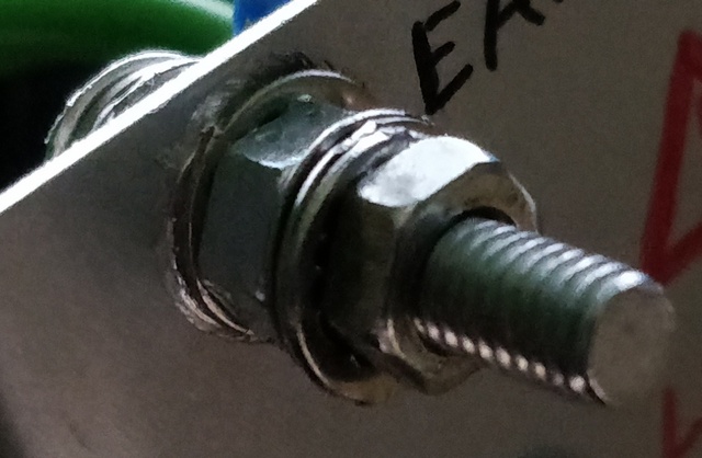
Earth connector on my DC blocker case
For other connectors - these must be isolated from the case. This is easy to miss - as a lot of phono connectors, 3.5mm connectors, DC connectors etc., are metal themselves and the ground is connected to the metal body and attaching that metal body to the case shorts the signal ground to the case, undoing the effect of the loop breaker, and creating multiple chassis connections themselves (causing more loops).
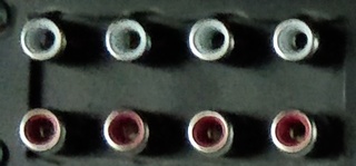
I solved this by buying a block of 8 phono connectors on a plastic mount and cutting a large square hole to allow them all to be used without shorting to the chassis.
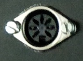
For my 5.1 input - I used a DIN connector. This is more convenient than 6 phono connectors, or three stereo 3.5mm connectors, but I used a 7 pin DIN so that the spare pin is used for the signal ground. My 7-core cable can then carry the 6 channels of audio, 1 signal return ground and the screen is instead connected to the chassis ground.
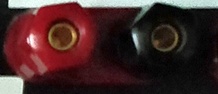
The speaker connectors are bare pins which run through the case shell, and therefore I isolated them by using the outer sleeve of old computer network cable over the pins. This not only prevents the speaker return from shorting to ground, but also the speaker outputs! Whilst you may think if the hole the speaker connector goes through is big enough, it won't short, bear in mind that if it becomes lose and moves around, that extra insulation helps.
Separate Power and Audio/Signal grounds
I used to do this a lot in order to prevent ground loops - sending just a single wire to an amplifier, with either the signal ground or power ground cut or broken with a 10 ohm resistor. This is wrong though and can introduce hiss, or more hum than before, as the power and signal ground will (mostly) follow the path of least resistance, down a single cable.
For a preamp - this sharing of the ground hasn't really caused me a problem - so it is still a valid method to use to reduce loops in the preamp section, so long as other principles are concerned. For power amplifiers though, this is where it can go wrong.
To achieve this objective, the signals grounds were connected to the input of each amplifier via the screened audio cables from my preamp board. The power grounds then went for each amplifier to the system star ground, at my PSU circuit board. For the stereo amplifier PCBs, I cut the ground trace in between the two amplifiers, so each amplifier is wired individually to the star ground.
The use of star grounding
I used star grounding technique for each system - one for the preamp (the phono interconnects ground), and one system ground for the power amplifier (the PSU ground).
For the power amplifier, there is a bit of a difference to a normal star ground though. In a normal star ground, all grounds are connected to the very same point (forming a star and hence the name). I however used the 'T' ground principle explained in Bonsai's guide.
My example is less of a 'T' and more a rectangle at the end of my PSU PCB - but the principle is the same, and connecting to this rectangle from left to right is:
- The capacitors from the PSU - has to be first as large charging currents are here.
- The loop breaker earth - doesn't cause noise itself, but doesn't care about noise and should be closest to the PSU for safety
- The ground from speaker protection - normally off and doesn't care about noise or create it, but high current under fault
- The speaker return - high current, and less sensitive to noise, 5 of these required
- The amplifier power grounds - high current, 5 of these required
- The signal ground - connects to the preamp star
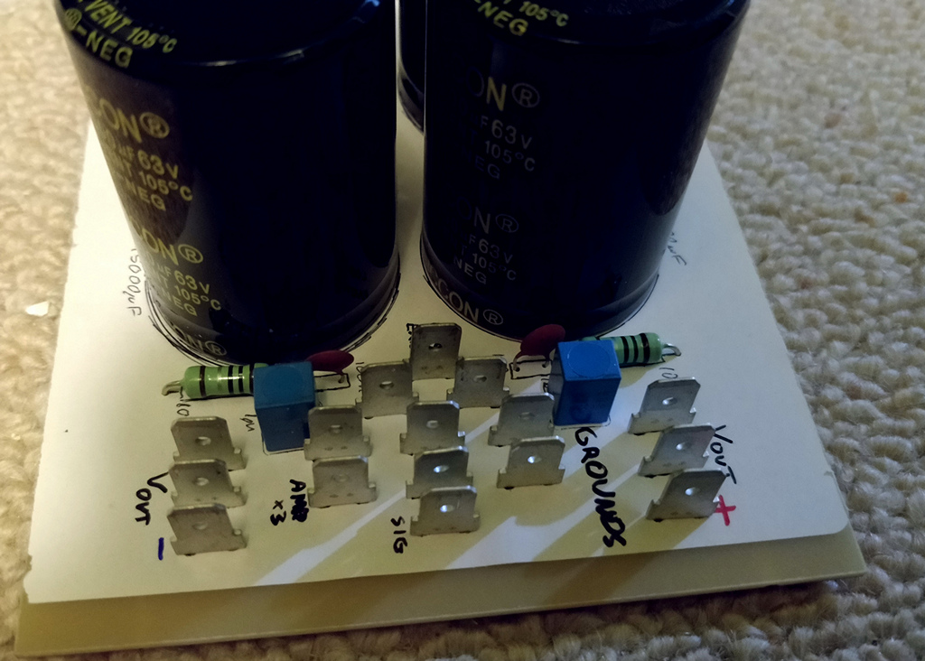
PSU, showing the various ground connectors
The preamp has a star ground at the phono interconnects. Here already my eight phono connectors (7 in use) are already connected altogether, so it's a good place to make a full star ground, therefore the following boards are grounded to this single point:
- The P05 +/-15V PSU ground
- The main preamp PCB ground - this board forms a second star for all 3 stereo channels of the preamp + PGA2310, the surround sound processor and digital delay
- The P06 phono preamp
- The P99 rumble filter
- The 7 DIN socket used for 5.1 channel input
- The connection to the power amplifiers system ground
The preamp star ground - at the phono connectors
The preamp section also contains digital circuits. The digital ground needs to connect to the preamp audio ground, and this is done on the main preamp PCB as it needs to be near the PGA2310 chips to avoid issues. This is done as a single connection only, and not at every PGA2310 chip.
After that single connection of the digital ground to the preamp ground, the rest of the digital grounds are isolated on their own, using a ground plane on the board where the PIC microcontroller is situated itself, and all other digital circuits are connected to the ground plane on this board itself.
Avoid loops
The technique above naturally does that, but unless you think about it in your layout, you could end up with a loop and it's not something you can identify on a multimeter until you disconnect ground wires and still see a connection on the meter.
A loop is when a ground path from one point to another has two different paths it can take. Each path will have a different resistance, but the electrons won't exclusively take the path of least resistance and you end up with a potential divider, and different ground potentials at the target.
I even did this myself on one of the first tests of the complete rebuild and found crazy amounts of noise and whine. That is because my original speaker protection had the speaker ground and digital input ground connected together, as well as the preamp having the digital ground connected to the preamp ground. This produced one massive loop from the speaker protector, to the PSU system ground, to the preamp ground, to the preamp PCB, to the PIC micro-controller board, and back to the speaker protector!
To break the loop, disconnecting one of the ground wires would have worked, but under fault it wouldn't be good to send the high fault current via the micro-controller board, preamp board etc to the ground. The digital part would also not be good to send via the preamp PCB, preamp star and amp PSU system ground either - this would pick up digital noise.
The speaker protector shouldn't have had those grounds connected on the PCB, so instead I modified it to cut the traces so ensure the fault ground is independent from the relay and digital input/output and continue to have separate wires for each. So, you can really see that you need to think about your wiring scheme and PCBs to ensure this is avoided!
Hum-breaking resistor at each amplifier
This is a technique in Bonsai's guide, and it makes sense. The idea of it is to cut the ground loop that would otherwise be formed from the several signal grounds of a stereo or multi-channel amplifier back to the preamp, and the power grounds back to the system ground and on to the preamp too.
The hum breaking resistor must appear after the amplifier's bias resistor though and connects from the signal ground after the bias resistor, to the power ground of the amplifier itself at the PSU decoupling capacitors.
It's also recommended to place a 100nF capacitor in series with the hum breaking resistor so high frequencies still have a short path to ground, otherwise the amps may oscillate.
On Project 19 at ESP, this means the circuit is modified like this:
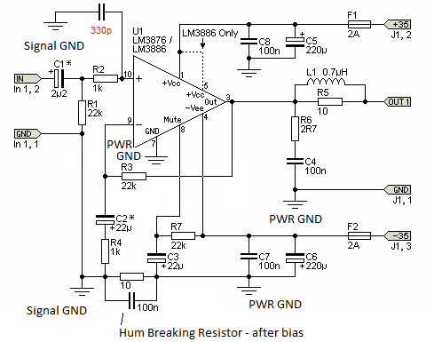
Modified P19 schematic with hum breaking resistor, and additional high frequency filtering.
The board itself needed traces cut and a few components and links soldered on to the bottom. This was a bit annoying to do and result is a bit messy, but it really worked very effectively. Having tried the setup without these changes initially, I still could not eliminate the hum until I did this. All three boards were modified in this way, with the mod done twice (once for each amp) on the two stereo boards.
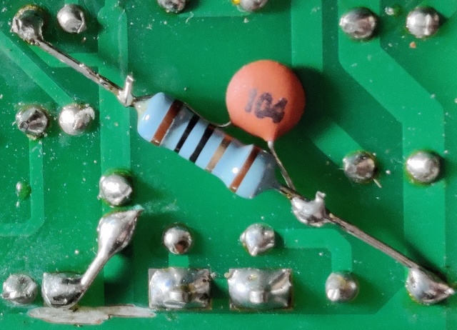
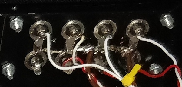
Modified P19 PCB, how the hum breaking resistor was installed
Low resistance cables for all grounds
Because ground is at (or in reality close to) 0V (zero volts) - any power that does flow through it will be of high current (because the voltage is so low). Cable resistance is an enemy of high current, and high resistance causes a change in voltage at either end of the cable, and it will vary between each component that is connected. These voltage differences are actually what causes hum in the first place, especially if there is a loop involved.
You can't eliminate resistance completely (hobbyists can't get super-conductors!) but avoid using tiny bell wire and/or cheap thin audio cables (really intended for headphones) for those grounds and make sure thick cable is used, and audio cables with fairly thick screening (check this last point carefully - I've brought thicker audio cable before, and it just contains more plastic and cumbersome to work with!).
Finally, to ensure the resistance is lower still - keep that cable short! Make it follow the shortest path end-to-end, whilst avoiding noise creating areas such as transformers, mains cable and high current DC cable. This is where layout needs to be thought about, i.e., having the system star close to the middle of your case and keeping audio circuits close to that.
Treating each single amplifier individually
I've kind of mentioned this above already. With a stereo amplifier sharing a single board, you might be fine to have only one ground running from that to the system ground.
In a multi-channel system, such as mine, there are three different boards, and five amplifiers. So that they all perform similarly, every amplifier should be connected to the system ground on its own. Having some amps share the ground (but not all) creates a problem. Furthermore, that shared ground will also have double the power flowing through it.
To achieve this, on my stereo P19 PCBs from ESP, I cut the common ground trace, and ran separate power grounds to the PSU, as well as the separate signal grounds to the preamp.

Cut ground trace
Tightly twisting wires, and keep them away from signal grounds
Twisting cables has two purposes: - makes them less sensitive to noise, because noise picked up is cancelled out by the second cable around it.
- For sensitive wires (such as audio) - twisting them makes them to be more immune to noise, as its 'pair' will help to cancel out noise and preventing noise from flowing in the same direction
- For power wires - twisting these reduces the amount of noise radiated from them (magnetism)
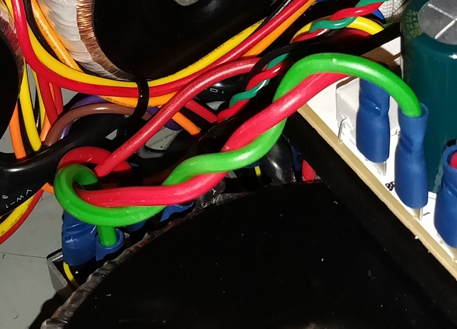
Twisted +/- DC pair from the rectifier to the PSU board / capacitors
For all wires to twist - twist only with its pair. Audio cables should be twisted with its signal return (ground). Power cables should be twisted with its partner.
For power cables - the important ones you really want to twist are:
- AC connectors from the main transformer to the bridge rectifier - these will be pulsing high AC current
- DC connectors from the bridge rectifier to the PSU board / capacitors - these will also be pulsing a 'chopped' DC waveform. Twist the + and - together.
- Mains cables - these are carrying AC. Twist live and neutral, includes the AC inputs to the transformers.
- DC connectors to each amplifier - these are high current. Twist the +, ground and - together.
- Speaker cables - high current, less critical to twist though and may not be practical (I did not)
Conclusion
Following the techniques above - for the first time since the 14 years since creation, my amplifier is pretty much noise free. No hum, hiss, whining or buzzing here and I'm very pleased as a result. Though it was never terrible before and always sounded great, there was always that hint of hum that was stubborn to remove, and now that removal of hum has finally been achieved.
That concludes details about my grounding. At this point, the audio part of the build is complete, but part of my build involves the control of the amplifier, so read on to see how I programmed the PIC microchip and interfaced that to the circuits and the user.
References and more reading:
HIFISONIX.COM - Ground Loops - design guide to minimise hum/
ESP - Earthing Your Hi-Fi - Tricks and Techniques
Neurochrome - Taming the LM3886 Chip Amplifier/
diyAudio.com - Audio Component
Grounding and Interconnection
diyAudio.com - Understanding star
grounding
Circuit Basics - A Complete Guide to Design and Build a Hi-Fi LM3886
Amplifier
Further pages here...