
Hi-Fi LM3886 5.1 channel amplifier, with digital control - Control Software
1 - Intro, 2 - The design, 3 - Pre-amplifier, 4 - Power Amplifiers, 5 - Power Supply, 6 - Grounding, 7 - Control - Hardware, 8 - Control - Software, 9 - Android App, 10 - Summary
Digital Control - Software
On this page...
- Software introduction
- Download
- Header file
- Initialisation and Configuration
- Timers
- Interrupts
- The main() method
- Output communication - LEDs, speaker mute relays and power relay (soft-start)
- Output communication - controlling the audio relays 74HCT595
- Output communication - controlling the volume level PGA2310
- Output communication - displaying on the LED display MAX7219
- Input events - checking for IR commands
- Output communication - writing out to Bluetooth RS232 transceiver
- Input events - receiving data from Bluetooth RS232 transceiver
- Input events - DC fault occurred
- Input events - loss of AC occurred and EEPROM writing
- Internal methods - power on/off sequence
- Internal methods - displaying the volume and active input
- Internal methods - Bluetooth AT commands
- Conclusion
Software introduction
The brains of the system, and the only 'programmable' part of the hardware, is an 8-bit PIC microchip. All other hardware is pre-made and designed to receive commands, and/or send commands.
When I first started the implementation, at the time, the hobbyist would typically code in PIC assembler language. Assembler is a low-level programming language that closely resembles the target machine code.
But programming with assembler is quite hard, especially for beginners and since I was going to use my first build for my final year university project, I was very worried about using assembler to do the job. It's one thing to blink a few LEDs and turn a stepper motor in computer labs using assembler - it's quite another to control several relays, switches, volume chips, a graphic LCD display (that I used at the time) and support RS232 communications.
Having learned Java, and a bit of C in the previous years at university, after some searching around, I found a good value C to assembler compiler named C2C, by Source Boost. C2C was a good start and I managed to get up and running with it quite well. The IDE is simple, but fast and not overwhelming.
C2C was later changed to BoostC, and that is what I use now and what all the code below is based on. I think it's a great implementation, easy to program and reads well. You can also try it for free for non-commercial projects which use less 4k ROM for PIC18 (2k for PIC16), which gives a great introduction. My complete v3.0 code comes in at 5.6k words (excluding Bluetooth / RS232 comms), so won't work in the free compiler. If you were ruthless, you could cut down to 4k and sacrifice some features or use different display modules.
I now find programming PICs in BoostC one of the most interesting and rewarding coding activities I do, and a very unique skill that I've not yet seen any other developer in my day job have. But it's not that hard, even though you do need some patience, as you don't know whether your code really works or what bugs arise until you burn it into the PIC and switch on your creation. There's no simulator to easily setup with all the external hardware needed.
To get that compiled code onto the PIC, you will need some extra hardware too - namely a PIC programmer.
I originally used a serial port programmer - the PIC JDM programmer. This needs a PC with the legacy RS232 9-pin serial port though, which is very rare these days. I do have a desktop PC with one still, but the last four laptops I've owned never had one. USB to RS232 adapters sadly do not work with it as they do not provide enough voltage.
To improve convenience, I built the UsbPicProg programmer. Their website and code updates are a bit inactive these days, but the programmer works very well, and you can build it yourself as I did. To build it, I etched my own dual layer board and using that JDM programmer one last time to burn provided hex file to the PIC18F2550. PCB layouts are even provided. Once you've got the firmware on the PIC18F2550 once, firmware upgrades can be programmed via USB, so that JDM programmer has been unused for years.
The UsbPicProg software works well, and with a bit of fiddling, even works well in Windows 10. You open up the hex file generated by the BoostC compiler/linker in the UsbPicProg interface, and program the target PIC via the UsbPicProg and an ICP cable. It programs and verifies the code pretty quickly.
Download
My source code is available on github.com. Should really cut your work down if you're basically building the exact same thing, but as a hobbyist, DO take it, look at it, learn it, fiddle with it and if you improve it, let me know!
Update: v3.0 linked above has had the following changes since my previous implementation:
- MAX7219 module power is switched on/off via a PNP transistor switch. This is to reduce data corruption by fully resetting the module each time I power on the amp
- IR remote control has a new 'function' mode. Pressing and holding the mute button brings up a function menu, and allows adjusting of the speaker levels, balance, triggers and surround modes that previously could only be done in the Bluetooth app.
- Monitoring a 5V USB trigger (which is connected to the TV) - allowing the amp to power on/off automatically when the TV is powered on/off
- Bit-bang methods have been tuned a bit (less code, faster processing)
- RS232 Bluetooth has been removed. The unpaired Bluetooth module consumes power when unpaired - which is 99.99% of the time so I just decided to remove it to save standby (and on) power consumption
Prior code is not on github, but the majority of the code for RS232 is there, but commented out.
Below I've described in a more detail how each section works with snippets which should interest the programmer inside you.
Header file
Variables and macros for the program I've placed into the header file. Static variables/arrays are also here.
Below is a reference of the variables and variables that are important. Note that this is not the complete header file though.
// Tasks
char cTask = 0;
#define TASK_INT_EXT0     0
#define TASK_RS232        1
#define TASK_INT_TX       2
#define TASK_INT_EXT1	    3
#define TASK_INT_EXT2     4
#define TASK_TIMER1_MUTE  5
#define TASK_TIMER1_FUNC  6
#define TASK_TIMER1       7

// LED and Relay outputs
#define POWEROUT (porta.0) // Output for the main power relays
#define MUTEOUT (porta.1) // Output for the unmute relay
#define IR_LED (porta.2) // Red IR LED pin
#define RED (porta.3) // Red LED pin
#define GREEN (porta.4) // Green LED pin
#define BLUE (porta.5) // Blue LED pin

// Pins for monitoring
#define PWR_FAIL (portb.0) // AC detection for when amp is unplugged - if this is high, then AC was removed
#define IR_PIN (portb.1) // IR detector input pin
#define DC_FAIL (portb.2) // Amp DC detection - if this is low, then in a fault condition!
#define EXT_POWER (portd.6) // Externally triggered power - if this is low, then a device connected by USB is on

// MAX7219 pins
#define LEDDATA (portb.3)
#define LEDCLOCK (portb.4)
#define LEDLATCH (portb.5)
#define LEDDISPON (portd.7) // v3.0 added this to control power Vss to MAX7219 - low = display on

// PGA2310 pins
#define VOLDATA (portc.0)
#define VOLCLOCK (portc.1)
#define VOLLATCH (portc.2)

// 74HCT595 pins
#define RELAYDATA (porte.0)
#define RELAYCLOCK (porte.1)
#define RELAYLATCH (porte.2)

// MAX7219 bit-bang delay
#define LEDDELAYUS 40

// Timer2 preloads for IR timing
// 21 for 208us on 10MHz, 1:8 postscaler
// 34 for 16MHz, 50 for 24MHz
#define IR_PR2_200US 21
// 92 for 872us on 10MHz, 1:8 postscaler
// 148 for 16MHz, 222 for 24MHz
#define IR_PR2_890US 92

// For setting TMR1 to 3072 (tmr1h=12) - so it interrupts after roughly 200ms at 10Mhz, 1:8 prescaler
#define TMR1H_SET 12
#define TMR1_1SEC 5

#define RX_BUFFER_SIZE	30

char iVolume = 0; // Overall system volume 0-255
char iMute = 0; // 1 if muted
char iMuteHeld = 0;
char iMuteWasPressed = 0;
signed char iFrontBalance = 0; // signed offset to front speakers left/right balance
signed char iRearBalance = 0; // signed offset to rear speakers left/right balance
signed char iRearAdjust = 0; // signed offset to rear speakers volume
signed char iCentreAdjust = 0; // signed offset to centre speaker volume
signed char iSubAdjust = 0; // signed offset to subwoofer volume

char iPower = 0; // 1 if powered on
char iPowerExternal = 0; // 1 if powered on by external USB trigger
char iActiveInput = 0; // The active input 0 to 3
char iTrigger = 1; // The active 12V trigger outputs - by default, trigger 1 on, trigger 2 off
char iSurroundMode = 1; // Surround sound mode. 0 = stereo, 1 = all 6 channels
char iExtSurroundMode = 1; // Surround sound decoding. 0 = internal hafler, 1 = external decoded via 5.1 input
char iFunctionMode = 0;

// Buffer and index pointer for RS232 receiving
//char iRS232Index;
//char rs232Buffer[RX_BUFFER_SIZE];

// Timer 1 overflow counting
char iTimer1Count = 0;
char iTimer1SecCounts = 0;
char iTimer1OffCount = 10;

// RC5 message time (~114ms) multiple
#define MUTE_HOLD_TIME 9
The convenience of this header file is to name the pins on the microchip so I can refer to them in the main c file, without having to remember that the RED LED is on RA3 (referred to as porta.3 in the software). It's also one place to set and adjust the timer preloads without changing multiple lines of code. All global variables are defined here too.
Initialisation and Configuration
Before a PIC can run code that you've written, it needs some configuration (done during programming), and initialisation (run in the code).
Configuration involves telling the PIC what speed to run at, how to run at that speed (what oscillator), what protection is in use (watchdog, code protection etc.) and so on.
Once a PIC powers up initially or after a reset - you need to tell it what pins are inputs, what are outputs, what speed the timers tick at, what speed to run serial ports at, what interrupts are active and so on. These kinds of settings are done in an init routine, because they are something you need to set, but these settings can be changed at runtime later (so are not set during programming).
Configuration registers
The PIC18F4455 datasheet has details of what the configuration registers set. This varies per PIC so check the specific datasheet.
BoostC can have a set of #pragma variables in the source code, which make it through to the hex file and UsbPicProg detects these and writes the result to the PIC during programming.
// Configuration registers
#pragma DATA    _CONFIG1L, 00001000b // USBDIV off, CPU divide by 2, PLL direct
#pragma DATA    _CONFIG1H, 10001101b // enable oscillator switchover, disable failsafe clock monitor, HS
#pragma DATA    _CONFIG2L, 00011111b // USB voltage regulator disabled, brownout set for 2.1 volts, hardware brownout only, PWRT disabled
#pragma DATA    _CONFIG2H, 00011110b // Watchdog timer disabled
#pragma DATA    _CONFIG3H, 10000000b // MCLR enabled, RB4:RB0 digital on POR
#pragma DATA    _CONFIG4L, 10000000b // Debug off, extended instructions disabled, LVP disabled, disable stack full/underflow reset
#pragma DATA    _CONFIG5L, 00001111b // Read code protection off
#pragma DATA    _CONFIG5H, 11000000b // Read EEPROM and boot block protection off
#pragma DATA    _CONFIG6L, 00001111b // Write code protection off
#pragma DATA    _CONFIG6H, 11100000b // Write EEPROM, boot block and config register protection off
#pragma DATA    _CONFIG7L, 00001111b // Table read protection off
#pragma DATA    _CONFIG7H, 01000000b // Boot block table read protection off
My configuration above is basically setting the bits in each configuration register appropriately. Many of these are defaults, however the keys ones are:
| Register | Bit Names | Bits | Use | My setting |
|---|---|---|---|---|
| CONFIG1L | CPUDIV1:CPUDIV0 | 43 | System Clock Postscaler Selection | 01 - the primary oscillator divided by 2 to derive system clock. As I use a 20MHz |
| CONFIG1H | FOSC3:FOSC0 | 3-0 | Oscillator Selection | 1101 - HS oscillator (High Speed crystal, with no PLL). This is the correct setting for an external crystal above 4MHz. |
| CONFIG2L | !PWRTEN | 0 | Power-up Timer Enable | 1 - which means it's disabled |
| CONFIG2L | BOREN1:BOREN0 | 2-1 | Brown-out Reset Enable | 11 - which means Brown-out Reset is enabled in hardware only |
| CONFIG2L | BORV1:BORV0 | 4-3 | Brown-out Reset Voltage | 11 - which means the minimum setting |
| CONFIG2L | VREGEN | 5 | USB Internal Voltage Regulator Enable | 0 - which means it's disabled (don't need it as not using USB) |
| CONFIG2H | WDTEN | 0 | Watchdog Timer Enable | 0 - which means it's disabled. Enabling the watchdog resets the PIC if code is unresponsive but prevents long delays from running. |
| CONFIG3H | PBADEN | 1 | PORTB A/D Enable | 0 - which means portb is digital on reset (not analogue) |
| CONFIG3H | MCLRE | 7 | MCLR Pin Enable | 1 - which means it's used to reset the PIC instead of an I/O pin |
| CONFIG4L | STVREN | 0 | Stack full/underflow reset enable | 0 - don't reset if this happens |
| CONFIG4L | LVP | 2 | Single-Supply ICSP Enable | 0 - don't support low voltage programming |
| CONFIG4L | ICPRT | 5 | In-Circuit Debug/Programming Enable | 0 - disabled |
| CONFIG4L | XINST | 6 | Extended Instruction Set Enable | 0 - legacy mode |
| CONFIG4L | DEBUG | 7 | Background Debugger Enable | 1 - Background debugger off. Allows RB6 and RB7 to be used. |
| CONFIG5L | CP3:CP0 | 3-0 | Code protection | 1111 - no read protection |
| CONFIG5H | CPD:CPB | 7-6 | Code protection | 11 - no read protection on EEPROM or boot block |
| CONFIG6L | WRT3:WRT0 | 3-0 | Write protection | 1111 - no write protection |
| CONFIG6H | WRTD, WRTB, WRTC | 7-5 | Write protection bits | 111 - no write protection on EEPROM, boot block or config register |
| CONFIG7L | EBTR3:EBTR0 | 3-0 | Table Read Protection | 1111 - no read protection |
| CONFIG7H | EBTRB | 6 | Boot Block Table Read Protection | 1 - no read protection |
The final #pragma tells BoostC what speed the system clock is, so that it gets the delay routines accurate.
// 20 MHz crystal but the system clock is 10MHz due to CPUDIV configuration
#pragma CLOCK_FREQ 10000000
Initialisation
Initialisation is called from the main() method (the entry point to running most programs). It is called before the endless loop starts in the main() method.
Its purpose is to set the configuration of everything we need, ports etc. Below is my initialise() method:
void initialise() {
    // IO ports setup
    trisa = 0x00; // all ouptuts
    porta = 0x00; // set to off
    trisb = 0x07; // RB0, RB1, RB2 are inputs
    portb = 0x00; // set to off
    trisc = 0xC0; // RC7 (Rx) and RC6 (Tx) are inputs
    portc = 0x04; // Set bit 2 on portc, the pga2310 latch /CS
    trisd = 0x40; // v3.0 - RB6 is an input
    portd = 0x00; // LED outputs off
    trise = 0x00; // All outputs (relay 74ht595)
    porte = 0x00; // All off

    osccon.IDLEN = 1; // Enter idle mode on sleep
    osccon.IRCF2 = 1; // IRCF2 to IRCF0 are 110 for 4MHz for RC_RUN mode to save power
    osccon.IRCF1 = 1;
    osccon.IRCF0 = 0;

    // ADC setup
    adcon0 = 0x00; //  ADC off
    adcon1 = 0x0F; // All digital I/O

    readData(); // Read in variables from EEPROM
    writeRelay(); // v1.1 moved to power on sequence

    // Timer calculator: http://eng-serve.com/pic/pic_timer.html
    // Timer 1 setup - interrupt every 87ms seconds 24MHz, 131ms 16MHz, 210ms 10Mhz
    t1con = 0x30;  //  00 11 0000 - 1:8 prescale, oscil off, internal clock, timer disabled
    iTimer1Count = 0; // Counter for number of interrupts
    tmr1h = TMR1H_SET; // Set TMR1 to 3072 (tmr1h 12)
    pie1.TMR1IE = 1; // Timer 1 interrupt
    pir1.TMR1IF = 0; // Clear timer 1 interrupt flag bit

    // Timer 2 setup - interrupt every 890us
    t2con = 0x29;  //  0 0101 0 01 - 1:6 postscale, timer off, 1:4 prescale
    // 10MHz settings
    pr2 = 92; // Preload timer2 comparator value - 0.00088320s
    pie1.TMR2IE = 1; // Timer 2 interrupt
    pir2.TMR2IF = 0; // Clear timer 1 interrupt flag bit

    // Setup for RB0 Interrupt [Power Fail]
    intcon.INT0IE = 1; // RB0 Interrupt enabled (for power fail)
    intcon2.INTEDG0 = 1; // RB0 interrupt should occur on rising edge
    intcon.INT0IF = 0; // Clear RB0 interrupt flag bit

    // Setup for RB1 Interrupt [IR LED]
    intcon3.INT1E = 1; // RB1 Interrupt (for IR receive)
    intcon2.INTEDG1 = 0; // RB1 interrupt should occur on falling edge
    intcon3.INT1IF = 0; // Clear RB1 interrupt flag bit

    // Setup for RB2 Interrupt [DC fail]
    intcon3.INT2E = 1; // RB2 Interrupt (for DC Fail)
    intcon2.INTEDG2 = 0; // RB2 interrupt should occur on falling edge
    intcon3.INT2IF = 0; // Clear RB2 interrupt flag bit

    intcon2.RBPU = 1; // Port B pull-ups disabled (otherwise DC fail is not detected)

    intcon.PEIE = 1; // Enables all unmasked peripheral interrupts (required for RS232)

    // No task at initialisation
    cTask = 0;

    // rs232 communications setup
    // SYNC = 0, BRGH = 1, BRG16 = 0
    // 10MHz Baud rate 9600 = 65 = ((10000000 / 9600) / 16) - 1
    //spbrg = 65; // 65 = ((10000000 / 9600) / 16) - 1
    //txsta = 0x26; // 00100110 - 8 bit, transmit enable, async mode, high speed, TSR empty, 9bit (0)
    //rcsta = 0x90; // 10010000 - serial port enabled, 8 bit reception, async mode continuous recieve, no frame error, no overrun error
    //baudcon = 0x42; // 01000010 - non-inverted, 8 bit generator, wake up on receive

    //pie1.RCIE = 1; // Usart interrupt receive (no send interrupt)
    //iRS232Index = 0;

    RED = 1; // Standby LED

    delay_s(2);

    // v3.0 altered display test
    ledOn();
    ledTest();
    delay_s(2);
    ledOff();

    //bluetoothSetup();

    enableInterrupts();
}
Note: The PIC pin configuration is on the previous page, see Table of I/O pins
Quite a lot is done there - so let's break it down:
- Ports - the TRIS and PORT registers are set. TRIS registers tell a pin whether it is an input or output. For example, portb has three input pins - RB0, RB1 and RB2 so it is set to 0x07 (in hex) or 00000111 in binary. The PORT register can be written to for pins set as output pins or read from for pins set as inputs. At initialisation, I set most outputs to off.
- OSCCON - here I set what happens when sleep() is called. It was experimentation only and unused.
- ADCON - here I setup the ADC (analogue to digital) feature. I don't use it at all, so ADC is off, and all ADC pins are set to allow digital I/O only
- UCON - USB is off
- Timer 1 - Here I setup the Timer 1, see below
- Timer 2 - Here I setup the Timer 2, see below
- RB0 - RB0 is an input connected to the loss of AC detector. Using INTCON and INTCON2 we can tell the PIC to raise an interrupt if this input goes high
- RB1 - RB1 is an input connected to the IR sensor. Using INTCON2 and INTCON3 we can tell the PIC to raise an interrupt if this input goes high. During the IR routine, we also change it later to interrupt on going low, but the initial detection is going high.
- RB2 - RB2 is an input connected to the speaker DC detector. Using INTCON2 and INTCON3 we can tell the PIC to raise an interrupt if this input goes low (i.e., an amp failure occurred - DC was detected)
- INTCON RBPU - Disable the built in Port B weak pull-ups (otherwise DC fail is not detected)
- INTCON PEIE - Enable all the peripheral interrupts (required for RS232)
- cTask - This is used for my task scheduler in the main() loop. It's set to zero for no task to run
- RS232 - SPBRG, TXSTA, RCSTA, BAUDCON and PIE1 deal with the setup of RS232 communications. This includes setting the baud rate to 9600 and setting the communication options. I used a common configuration of 8 bit communication, asynchronous, no check or frame error bits. The datasheet has all the options, including calculations for the baud rate, in my case ((10000000 / 9600) / 16) - 1 with 10000000 being 10MHz, 9600 being the baud rate. Finally, PIE1 sets the interrupt on receive option.
- I delay a few seconds before setting up the external hardware, just to allow the power supply to stabilise more.
- ledSetup(), ledOn(), ledTest() - options for the MAXL7219 drivers, and a test
- bluetoothSetup() - options for the Bluetooth module (AT commands). Causes a delay.
- ledClear(), ledOff() - switch off the MAX7219 display
- enableInterrupts() - enables all interrupts. System is now ready to use.
Remember, this initialisation routine only runs when you first plug the mains cord into the unit. When the amps are powered off, the PIC is still running 24x7. If you intend to not leave the PIC on standby, the delays in the initialisation could probably be shortened a lot, but I did not experiment.
Before we move on to the main code and routines, I'll explain a few concepts with PIC (and most microcontroller) features that are used here.
Timers
Five timers are built in to the PIC18F4455, Watchdog, Timer0, Timer1, Timer2 and Timer3, and I use 2 of them. They run independently of the code, and when running, can cause interrupts when they count fully (the counter register overflows).
Timer 1
Timer 1 is used as a 200ms counter. It's used to detect IR button hold (for function mode) and also used to check if a DC fault has cleared. It also exits function mode after a certain amount of idle time and run a 10 second countdown before powering off when the external power is powered down. In the past it was also useful when I used an LCD display, allowing it to reset back to the standard information display and turn off the backlight after an event.
In the initialisation, I set the timer to a high interval of 200ms (milliseconds). 200ms is picked because it is longer than the RC5 signal time (114ms) but shorter than two of them. It also divides easily into 1 second.
Timer 2
Timer 2 is used for timing pulses on the RC5 infrared communications. This allows the IR commands to be received via interrupts on both this Timer 2 ticking at just shy of 890 μs (microseconds) and the IR receiver changing state. The 890 μs timer needs to be more accurate, though there is a little leeway.
A great resource for calculating the setup values for a timer is here - http://eng-serve.com/pic/pic_timer.html. By specifying your clock speed, it gives the values needed to setup the timer to interrupt at a period needed.
The code only turns on the timers when they are needed - i.e., an event occurred, or IR state changed. This is for efficiency and would allow the PIC to sleep too (though I didn't implement that in the end).
Interrupts
There are two ways of detecting events - polling for them in your code by constantly checking an input, or letting the PIC do the checking for you and firing an interrupt.
Polling is often done, but the PIC and C compiler I'm using is not multi-threaded and there is no OS giving you multi-tasking, so you cannot have one thread polling an input state constantly, whilst another thread does other work.
You can poll your inputs in the main() routine, which will run whenever nothing else is running. This is fine for task that do not need a fast response time (like the external USB power detection).
For the fastest response time though, the alternative is the interrupt routine. This routine basically allows us to say 'an event has happened, stop whatever you are doing immediately and handle it'.
On something critical - such as the DC failure, or the loss of AC to immediately write data to EEPROM, we want these events to be picked up and actioned immediately - a perfect example of what an interrupt routine can be used for.
I'm also using the interrupt routine for other tasks too, these being when timers overflow, IR sensor received a signal, RS232 received data. This is because it is convenient for the PIC to detect these events and immediately act on them in the Interrupt routine. Interrupts can also wake the PIC up from sleep, if you decide to sleep whenever there is no activity (saving power).
Be warned though - when an Interrupt occurs, another one cannot occur until the first is processed. This means code in the interrupt routine needs to be short, simple and swift. Long running commands, such as time delays, writing output to LED displays, serial comms, rs232 comms etc. are best avoided directly in the interrupt routine.
The solution to this is to put a simple task scheduler in the main loop (details later) so that the interrupt routine can flag 'there's something to do', then exit and leave the main program to schedule it and run it.
The main() method
The main() method is where the code starts running, and mine is pretty simple:
- Run the initialise method
- Loop infinitely
//-----------------------------------------------------------------------------
// MAIN PROGRAM
//------------------------------------------------------------------------------
void main() {
    initialise();

    while (1) {
        // Task scheduler
        // If there are tasks to be performed, find out the
        // most recent task from the array and execute it
        while (cTask > 0) {
            if (cTask.TASK_INT_EXT2) {
                // A DC fault occurred - show on display
                showFault();
                t1con.TMR1ON = 1; // Switch on the timer - will reset fault if it clears within 5 seconds
                cTask.TASK_INT_EXT2 = 0;
            } else if (cTask.TASK_INT_EXT0) {
                // Power fail occurred
                // When power supply is disconnected, save variables to EEPROM
                saveData();
                cTask.TASK_INT_EXT0 = 0;
            } else if (cTask.TASK_TIMER1_MUTE) {
                // Mute and update display
                doMute();
                //sendRS232Status();
                showVolume();
                ledWrite();
                // reset the timer
                timer1Reset();
                cTask.TASK_TIMER1_MUTE = 0;
            } else if (cTask.TASK_TIMER1_FUNC) {
                // enter function mode
                iFunctionMode = 1;
                // Show first function
                functionDisplay();
                // turn off the timer
                timer1Reset();
                cTask.TASK_TIMER1_FUNC = 0;
            } else if (cTask.TASK_TIMER1) {
                onTimer1(); // Timer 1 has finished counting
                cTask.TASK_TIMER1 = 0;
            } else if (cTask.TASK_INT_EXT1) {
                rc5Process(); // IR sensor received a signal
                IR_LED = 0; // Ensure LED is off
                cTask.TASK_INT_EXT1 = 0;
            //} else if (cTask.TASK_RS232) {
            //    rs232CommandReceived();
            //    cTask.TASK_RS232 = 0;
            }
        }

        // Poll for EXT_POWER
        // if EXT_POWER is low (USB trigger high), iPower is off
        // v1.1 and not previously powered on externally
        if (!EXT_POWER && !iPower && !iPowerExternal) {
            // Powered on by external appliance
            iPowerExternal = 1;
            // set the input to the trigged input (input 1) = in2 on the tda7439
            iActiveInput = 0;
            doPower();
        }
        // if EXT_POWER is high (USB trigger low), iPower is on, and was powered on externally
        // ..then power off
        // This is done in a countdown timer - see onTimer1();
        // v1.1 If no external power signal, and power is off anyway, reset the iPowerExternal indicator
        if (EXT_POWER && !iPower) {
            iPowerExternal = 0;
        }
    }
}
Inside the infinite loop, there is a task scheduler which checks the cTask variable for any bits that are set in that 8-bit character. This scheduler will allow up to 8 different tasks, and I use 5.
The if ... else statement then prioritises those tasks in order of importance. This is so if two interrupts happened at pretty much the same time, the most important one would execute first. This priority is:
- DC failure [TASK_INT_EXT2] - in the scenario of a faulty amplifier. The muting of the speaker relay is done in the interrupt routine itself because it needs to happen immediately, but the next level of priority is to display to the user that a fault has occurred, and then start the timer (5 second timer1), which will check and clear the fault if it is gone
- Loss of AC [TASK_INT_EXT0] - in the scenario that the power is lost to the whole unit, the next level of priority is to save the data to EEPROM, before the PSU capacitors empty and our PIC shuts down. EEPROM data should not be written directly in the interrupt routine itself, since writing to EEPROM can generate interrupts itself.
- Timer 1 tasks - there are several
- [TASK_TIMER1_MUTE] Mute timer elapsed (and mute button was not held) - this happens after 0.2 seconds. In this case, mute or unmute the amp
- [TASK_TIMER1_FUNC] Mute button was held for 1.5 seconds - enter the function mode. This changes the function of the volume and input up/down buttons on the remote to allow additional setting adjustments
- [TASK_TIMER1] Standard timer 1 tick (every second) - does DC fault checks and also runs a power off timer if USB power is removed (and the amp is on)
- IR signal received [TASK_INT_EXT1] - this is to handle a user pressing buttons on the remote control, and process that command
- RS232 data received [TASK_RS232] - this is to handle a user sending a command via the Bluetooth connection - removed as of July 2022
Outside the task schedule, checks are made to the EXT_POWER pin. If this goes low, then USB power is detected. If the amp is off and not previously powered on by USB power, then it will power on.
If the EXT_POWER pin is high, USB power is off. If the amp is already off, reset the powered on externally variable. Powering off the amplifier when it is on and USB power is removed is actually only checked every second in the onTimer1() function, as a countdown is run before powering off.
Now I shall move on to describing how each event is handled in some more detail.
Output communication - LEDs, speaker mute relays and power relay (soft-start)
The communication here is the most simple - on or off, or basically set a pin high, or set it low. In my .h (header) file (see above), I've named all pins for convenience and easy adjustment.
To set a pin, e.g., the colour Red on the Tri-colour LED:
RED = 1;
To turn it off again:
RED = 0;
And that's it! RED maps to pin 3 on PORTA as defined in my header. You could also put porta.3 = 1 (or 0) too. Throughout, you will see many examples of me setting and clearing outputs.
Output communication - controlling the audio relays 74HCT595
The five audio relays and two 12V trigger outputs are controlled by the PIC. These switch between 4 different stereo inputs, between internal and external 5.1 decoding, and outputs to drive external equipment via a 12V trigger.
Rather than consume 7 pins on the PIC microprocessor itself, the 12V outputs (relays and triggers) are controlled by a serial communication, needing only 3 pins.
A 74HCT595 shift register logic chip is installed on the preamp board, which receives a single byte (8 bits) by clocking in each individual bit (true/false) value, one at a time. Once all bits are received, the 74HCT595 will then put that byte on its parallel output pins (all 8 of them). A ULN2003A allows those low current 5V pins (7 of them at least) to drive higher current, 12V outputs.
The PIC writes the byte to the shift register via a serial communication. It does this in software by a process named as 'bit-banging'.
/******************************************************
  Apply relay selection to the 74HCT595 shift register
*******************************************************/
void writeRelay() {
    char iRelay = 0; // initialised empty

    // V2.0 changed outputs
    // TRG 1 = 00000001  0x01
    // TRG 2 = 00000010  0x02
    // INP 1 = 00000100  0x04
    // INP 2 = 00001000  0x08
    // INP 3 = 00010000  0x10
    // INP 0 = 00100000  0x20
    // SUR M = 01000000  0x40

    // Set surround mode relay if Active Input is 0 and ExtSurround is on
    if (iExtSurroundMode && (iActiveInput == 0)) {
        // Set bit 7
        iRelay = ((iRelay & 0xBF) + 0x40);
    }

    // Write selected input to input byte
    switch (iActiveInput) {
        // For each input, take the existing selected and logic AND with 0x43 (01000011) so the status
        // of the power and surround switch remains. Then add the representation of the input
        case 0:
            // Clear bits 2 to 5, Set bit 5,
            iRelay = ((iRelay & 0x43) + 0x20);
            break;
        case 1:
            // Clear bits 2 to 5, Set bit 2,
            iRelay = ((iRelay & 0x43) + 0x04);
            break;
        case 2:
            // Clear bits 2 to 5, Set bit 3,
            iRelay = ((iRelay & 0x43) + 0x08);
            break;
        case 3:
            // Clear bits 2 to 5, Set bit 4,
            iRelay = ((iRelay & 0x43) + 0x10);
            break;
    }

    if (iTrigger <= 3)
        iRelay += iTrigger;

    // v1.1 if power is off, disable all relays (to reduce standby current) and triggers
    if (!iPower)
        iRelay = 0;

    // Lower latch
    RELAYLATCH = 0;

    for (char cBitSelect = 0x01; cBitSelect; cBitSelect <<= 1) {
        if (iRelay & cBitSelect)
            RELAYDATA = 1; // Serial data output high
        else
            RELAYDATA = 0;

        RELAYCLOCK = 1; // Clock set high, so bit is loaded onto the shift register
        RELAYCLOCK = 0; // Clock cleared
    }

    // Load the new register
    RELAYLATCH = 1; // Set the latch to high so contents of shift register are put on the parallel output
}
This method (writeRelay) is basically doing two things. First it calculates a single byte which contains the true/false values for each relay and trigger, and secondly, it uses a for loop which tests each bit in that byte to put on the serial data line and pulses the serial clock high and low so the 74HCT595 reads it in.
Why not use hardware? The PIC does have a SPI hardware module which means you don't have to do bit-banging like I have, but it's not in a convenient place as the SPI clock pin is RB1 - meaning I couldn't use that for external interrupt, and the SPI data pin is on RC7, meaning I couldn't use the RS232 receive. The clock pin SCL is on RB1 so would also prevent using that pin as an external interrupt.
Bit banging a single byte, or even 6 bytes (for the PGA2310) is quick enough! Other PICs may use different pins though, and you could choose to use SPI hardware instead.
The code comments above details how the method above works, so you can understand a bit more detail what line of code does what.
Output communication - controlling the volume level PGA2310
This is similar to the relay method, but the difference is it is writing 6 bytes instead of 1. That's 1 unsigned byte (representing 0 to 255) representing the volume level per channel.
The PGA2310s are daisy chained, and once a chip has received two bytes and starts receiving more (which the latch is still low), the first bytes it has received start get clocked out to the next chip in the chain.
For my setup, the PGA2310 controlling the volume level for the subwoofer and centre channels is the last in the chain, so the PIC must send the volume levels for these channels first. The levels for rear right and left follow, and front right and left channels is the last two bytes to be sent.
/******************************************************
  Apply volume levels (6 channels) to PGA2310 chips
*******************************************************/
void writeVolumes() {
    char n; // Loop counter
    char byteVolume[6] = {0,0,0,0,0,0};

    // Set front levels based on balance setting
    if (iFrontBalance == 0) {
        byteVolume[4] = iVolume; // Right balance adjust (reduce left channel)
        byteVolume[5] = iVolume; // Set other channel to volume level
    } else if (iFrontBalance > 0) {
        byteVolume[4] = getAdjustedVolume(iFrontBalance * -1); // Right balance adjust (reduce left channel)
        byteVolume[5] = iVolume; // Set other channel to volume level
    } else {
        byteVolume[5] = getAdjustedVolume(iFrontBalance); // Left balance adjust (reduce right channel)
        byteVolume[4] = iVolume; // Set other channel to volume level
    }

    // Set rear levels based on balance setting and adjustment
    if (iRearBalance == 0) {
        byteVolume[2] = getAdjustedVolume(iRearAdjust); // Rear level adjust
        byteVolume[3] = getAdjustedVolume(iRearAdjust); // Rear level adjust
    } else if (iRearBalance > 0) {
        byteVolume[2] = getAdjustedVolume((iRearBalance * -1) + iRearAdjust); // Right balance adjust (reduce left channel)
        byteVolume[3] = getAdjustedVolume(iRearAdjust); // Adjust other channel only
    } else {
        byteVolume[3] = getAdjustedVolume(iRearBalance + iRearAdjust); // Left balance adjust (reduce right channel)
        byteVolume[2] = getAdjustedVolume(iRearAdjust); // Adjust other channel only
    }

    // Set centre and sub woofer levels based on each adjustment
    byteVolume[1] = getAdjustedVolume(iCentreAdjust); // Centre level adjust
    byteVolume[0] = getAdjustedVolume(iSubAdjust);  // Sub level adjust

    // If set to stereo, clear first 4 bytes (rear l/r, centre, sub)
    if (!iSurroundMode) {
        for (char i = 0; i < 4; i++)
            byteVolume[i] = 0;
    }
    // If muted (volume zero or iMute is 1), set all to zero regardless of levels
    if ((iVolume == 0) || (iMute == 1)) {
        for (char i = 0; i < 6; i++)
            byteVolume[i] = 0;
        // Display correct LED colour - green for muted
        GREEN = 1;
        BLUE = 0;
    } else {
        // Blue for active
        GREEN = 0;
        BLUE = 1;
    }

    // Set latch to low
    VOLLATCH = 0;

    for (n = 0; n < 6; n++) { // 6 bytes to send
        // MSB first
        for (char cBitSelect = 0x80; cBitSelect; cBitSelect >>= 1) {
            // Clear clock for next bit
            VOLCLOCK = 0;

            if (byteVolume[n] & cBitSelect) // the set bit position in cBitSelect in vol is set, output high
                VOLDATA = 1;
            else
                VOLDATA = 0;

            // Raise clock so serial bit output is sent
            VOLCLOCK = 1;
        }
    }
    // Set latch to high
    VOLLATCH = 1;
}

/******************************************************
 Adjust the volume level and return the result, from 0 to 255 only
 *******************************************************/
char getAdjustedVolume(signed char iVolAdj) {
    // Returns an adjustment to the volume, floor at zero and ceiling at 255
    char iResult = iVolume + iVolAdj;
    // Prevent overflow
    if (iVolAdj < 0) { // Negative, new level should always be less than overall
        if (iResult > iVolume)
            iResult = 0;
    }
    else { // Positive, new level should be greater than overall
        if (iResult < iVolume)
            iResult = 255;
    }
    return iResult;
}
Like the relay method, this one (writeVolumes) is basically doing two things. First it calculates a volume level byte per channel, by adjusting the balance and rear/centre/sub level adjustments to the overall volume to which are stored in an array. Secondly, it uses a for loop which tests each bit in that byte in a position in that array to put on the serial data line, and pulses the serial clock low and high so the PGA2310 reads it.
The loop is longer - 48 iterations because of 6 bytes to write (8 bits * 6), but the operations that occur in the loop are simple and work very well. Again, code comments detail the specific lines.
Output communication - displaying on the LED display MAX7219
The MAX7219 is my third serial device, and again the bytes are sent to it in a very similar method.
The MAX7219 expects two bytes. The first is the 'command' which will be a hex value mentioned in the datasheet, or a number from 1 to 8 to say which digit to write to. The second byte is a 'value', which is either a value relevant for that command (usually 1 or 0), or a hex value to specify which segments to set active on that digit.
It's a very convenient chip to use and can be daisy chained too. I use two modules, so this allows me to output content to 16 digits with just 3 data pins on the PIC.
Without the MAX7219, in an extreme case of driving every segment of every display directly - I'd need 128 pins! That's 7 segments plus the dot multiplied by 16. Traditional BCD to 7-segment decoders would half that only and prevent me displaying letters anyway. Multiplexing (and Charlieplexing) reduces pin usage further (as well as power consumption) but would need a dedicated chip anyway. MAX7219 does it all for us.
So, to write to the display and display numbers or (some) letters on those 16x 7-segment displays, I write 32 bytes in total. This is done in eight separate serial writes consisting of four bytes each - that's two bytes (command and value) for the second module in the daisy chain, and two bytes for the first.
Configuration - before I use the MAX7219, a number of configuration commands need to be written in order for it to display what I need. These are:
- Scan limit - 0x0B 0x07 : Scan all 8 digits in the display
- Decode mode - 0x09 0x00 : Do not decode - we could tell it to decode the bytes sent as BCD and let it display the numbers on the 7-segment displays, but that would prevent displaying letters
- Intensity - 0x0A 0x06 : Set the intensity to 13/32. This uses built in PWM so the display is not at completely full brightness, but bright enough to be clearly visible through my tinted plastic front panel
Additionally, I also use the command 0x0C followed by 1 or 0 to start-up or shutdown the display.
As for displaying the data on the segments, because I wanted to display letters as well as numbers on the display, I had to control the individual segments directly.
Fortunately, after some searching around, someone has already done great work already to produce an ASCII to 7-segment conversion table, which I found here.
I adjusted this array (manually) get the final value for my header file. I used to do it in software, but as of July 2022 I adjusted the bytes in the source array to the corrected values (using a spreadsheet formula to adjust the original). This saves execution time and code size at the PIC. Compared to the original, mine has the bits for each value shifted one to the right - so the representation of ASCII 'A' is 0xEE for the MAX7219 is 0x77, or 0xF7 if we want the dot to display too.
In software (the ledChar method), I still need to take off 0x20 from the input character to decode, because the ASCII array starts at 0x20 (every character in ASCII before that is not printable).
The LED character code I use is below:
/**************************************************************************************
    LED Display Functions
**************************************************************************************/

char ledData1[8];
char ledData2[8];

// Converts a string of characters into decoded 7 segment bytes for LED character array
// Optionally writes these bytes to LED displays
void ledPrint(char iLine, unsigned char *s) {
    char dig;
    for (dig = 0; dig < 8; dig++) {
        if (*s) {
            if (iLine == 1)
                ledData1[dig] = displayASCIItoSeg[*s++ - 0x20];
            else
                ledData2[dig] = displayASCIItoSeg[*s++ - 0x20];
        } else {
            if (iLine == 1)
                ledData1[dig] = 0;
            else
                ledData2[dig] = 0;
        }
    }
}

// Converts an ASCII char to decoded byte and places it in LED array
// Support decimal places
void ledChar(char iChar, char iHasDot) {
    char iDecoded = displayASCIItoSeg[iChar - 0x20];
    if (iHasDot)
        iDecoded = iDecoded | 0x80;
    if (ledCurrentLine == 1) {
        ledData1[ledCurrentCol] = iDecoded;
    } else {
        ledData2[ledCurrentCol] = iDecoded;
    }
    if (ledCurrentCol < 8)
        ledCurrentCol++;
}

// LED test function
void ledTest() {
    ledPrint(1, "Init on");
    ledPrint(2, "Testing");
    ledWrite();
}


// Setup the MAX7219 LED displays by sending the required configuration bytes
void ledSetup() {
    // Scan limit
    ledLatchDown();
    ledSendChar(0x0B);
    ledSendChar(0x07); // Scan all 8 digits
    ledSendChar(0x0B);
    ledSendChar(0x07); // Scan all 8 digits
    ledLatchUp();

    // Set no decode mode
    ledLatchDown();
    ledSendChar(0x09);
    ledSendChar(0);
    ledSendChar(0x09);
    ledSendChar(0);
    ledLatchUp();

    // Set intensity
    ledLatchDown();
    ledSendChar(0x0A);
    ledSendChar(0x06); // A: 21/32, 8: 17/32, 6:13/32
    ledSendChar(0x0A);
    ledSendChar(0x06); // A: 21/32, 8: 17/32, 6:13/32
    ledLatchUp();
}

// Start LED display
void ledOn() {
    // v3.0 Power on and setup
    LEDDATA = 0;
    LEDCLOCK = 0;
    LEDLATCH = 1;
    LEDDISPON = 0;
    //delay_s(1);
    delay_ms(250);
    ledSetup();

    // No shutdown
    ledLatchDown();
    ledSendChar(0x0C);
    ledSendChar(0x01); // no shutdown
    ledSendChar(0x0C);
    ledSendChar(0x01); // no shutdown
    ledLatchUp();
    // Startup time delay
    delay_us(250);
}

// Shutdown LED display
void ledOff() {
    // Shutdown
    ledLatchDown();
    ledSendChar(0x0C);
    ledSendChar(0x00); // shutdown
    ledSendChar(0x0C);
    ledSendChar(0x00); // shutdown
    ledLatchUp();
    // v3.0, remove the power
    LEDDISPON = 1;
    delay_ms(100);
}

// Write the bytes set in each array to the MAX7219 LED displays
void ledWrite() {
    char n;
    char d = 7; // Characters in array are written out backwards so start from furthest (7)

    // Loop through digits 0 to 8 (addressed as 1 to 9)
    for (n = 1; n < 9; n++) {
        // Writing character to second device
        ledLatchDown();
        ledSendChar(n); // Digit to write
        ledSendChar(ledData2[d]); // Data to write

        // Writing character to first device
        ledSendChar(n); // Digit to write
        ledSendChar(ledData1[d]); // Digit to write
        ledLatchUp();
        d--; // Decrement array counter
    }
}

void ledLatchDown() {
    // Load the new register
    LEDDATA = 0;
    LEDCLOCK = 0;
    LEDLATCH = 0; // Clock must fall so that last bit is clocked out
}

void ledLatchUp() {
    // Load the new register
    LEDLATCH = 1;
    LEDCLOCK = 0; // Clock must fall after latch raised
    LEDDATA = 0; // Data to default
    delay_us(LEDDELAYUS); // Need to delay before starting again
}

// Write a single piece of data (byte) out serially
// Uses bit-banging to control protocol and delays
void ledSendChar(char iData) {
    for (char cBitSelect = 0x80; cBitSelect; cBitSelect >>= 1) {
        LEDCLOCK = 0; // Clock cleared
        if (iData & cBitSelect)
            LEDDATA = 1;
        else
            LEDDATA = 0;
        LEDCLOCK = 1; // Clock set high, so bit is loaded onto the shift register
    }
}
For reference, here is the ASCII to 7-segment array, to which I adjusted slightly to display the uppercase T differently and shifted bits one to the right. It's from the header file:
// This table, taken from http://www.ccsinfo.com/forum/viewtopic.php?p=57034 is ideal for writing the converted character out
// However as the dot is the MSB for the MAX7219 when writing, bit shift 1 to the right
// Converted using spreadsheet formula ="0x"&RIGHT("0"&DEC2HEX(BITRSHIFT(HEX2DEC(RIGHT(A1,2)),1)),2)
// Modification - capital T output differently
const char displayASCIItoSeg[] = {// ASCII to SEVEN-SEGMENT conversion table
    0x00,       // ' ',
    0x00,       // '!', No seven-segment conversion for exclamation point
    0x22,       // '"', Double quote
    0x00,       // '#', Pound sign
    0x00,       // '$', No seven-segment conversion for dollar sign
    0x00,       // '%', No seven-segment conversion for percent sign
    0x00,       // '&', No seven-segment conversion for ampersand
    0x20,       // ''', Single quote
    0x4E,       // '(', Same as '['
    0x78,       // ')', Same as ']'
    0x00,       // '*', No seven-segment conversion for asterix
    0x00,       // '+', No seven-segment conversion for plus sign
    0x00,       // ', '
    0x01,       // '-', Minus sign
    0x00,       // '.', No seven-segment conversion for period
    0x00,       // '/', No seven-segment conversion for slash
    0x7E,       // '0',
    0x30,       // '1',
    0x6D,       // '2',
    0x79,       // '3',
    0x33,       // '4',
    0x5B,       // '5',
    0x5F,       // '6',
    0x70,       // '7',
    0x7F,       // '8',
    0x7B,       // '9',
    0x00,       // ':', No seven-segment conversion for colon
    0x00,       // ';', No seven-segment conversion for semi-colon
    0x00,       // '<', No seven-segment conversion for less-than sign
    0x09,       // '=', Equal sign
    0x00,       // '>', No seven-segment conversion for greater-than sign
    0x65,       //'?', Question mark
    0x00,       // '@', No seven-segment conversion for commercial at-sign
    0x77,       // 'A',
    0x1F,       // 'B', Actually displayed as 'b'
    0x4E,       // 'C',
    0x3D,       // 'D', Actually displayed as 'd'
    0x4F,       // 'E',
    0x47,       // 'F',
    0x5E,       // 'G', Actually displayed as 'g'
    0x37,       // 'H',
    0x30,       // 'I', Same as '1'
    0x3C,       // 'J',
    0x00,       // 'K', No seven-segment conversion
    0x0E,       // 'L',
    0x00,       // 'M', No seven-segment conversion
    0x15,       // 'N', Actually displayed as 'n'
    0x7E,       // 'O', Same as '0'
    0x67,       // 'P',
    0x00,       // 'Q', No seven-segment conversion
    0x05,       // 'R', Actually displayed as 'r'
    0x5B,       // 'S', Same as '5'
    0x70,       // 'T', Displayed as 7
    0x3E,       // 'U',
    0x00,       // 'V', No seven-segment conversion
    0x00,       // 'W', No seven-segment conversion
    0x00,       // 'X', No seven-segment conversion
    0x3B,       // 'Y',
    0x00,       // 'Z', No seven-segment conversion
    0x00,       // '[',
    0x00,       // '\', No seven-segment conversion
    0x00,       // ']',
    0x00,       // '^', No seven-segment conversion
    0x00,       // '_', Underscore
    0x00,       // '`', No seven-segment conversion for reverse quote
    0x7D,       // 'a',
    0x1F,       // 'b',
    0x0D,       // 'c',
    0x3D,       // 'd',
    0x6F,       // 'e',
    0x47,       // 'f', Actually displayed as 'F'
    0x5E,       // 'g',
    0x17,       // 'h',
    0x10,       // 'i',
    0x3C,       // 'j', Actually displayed as 'J'
    0x00,       // 'k', No seven-segment conversion
    0x0E,       // 'l', Actually displayed as 'L'
    0x00,       // 'm', No seven-segment conversion
    0x15,       // 'n',
    0x1D,       // 'o',
    0x67,       // 'p', Actually displayed as 'P'
    0x00,       // 'q', No seven-segment conversion
    0x05,       // 'r',
    0x5B,       // 's', Actually displayed as 'S'
    0x0F,       // 't',
    0x1C,       // 'u',
    0x00,       // 'v', No seven-segment conversion
    0x00,       // 'w', No seven-segment conversion
    0x00,       // 'x', No seven-segment conversion
    0x3B,       // 'y', Actually displayed as 'Y'
    0x00        // 'z', No seven-segment conversion
};
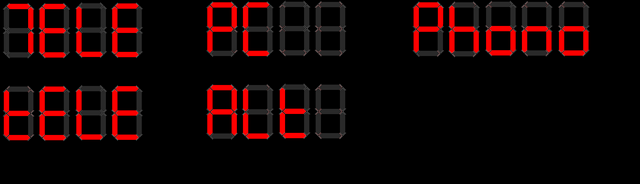
Examples of displaying my input names on the 7-segment displays. I preferred the alternative uppercase T for TELE instead of tELE. There's
no clear way to display the letter V though! PC, Phono and Alt (instead of Aux!) works well though.
The complete sequence to displaying data is:
- ledPrint() is called, with parameters 1: Which line to display on and 2: What to display
- ledPrint() then calculates the bytes to write out to the MAX7219 for displaying, and writes them to an array, with help of the displayASCIItoSeg array
- ledWrite() is called separately if the code should write out to the display. Both displays are written at once, so if the code is changing two rows of output, the alterations should only be written to the display once.
- ledWrite() then loops through the 8 bytes in the two arrays (one per line), and then bit-bangs those bytes in the array to the relevant 7-segment digit. 32 bytes written in total, with the output loaded 8 times.
Alternative ledChar() can display and update a single character, leaving the rest intact. Before calling ledChar(), the ledCurrentLine and ledCurrentCol variables should be set first. The ledCurrentCol is automatically incremented with each ledChar() call.
Input events - checking for IR commands
For IR commands, even in the original build of the preamp in 2005, I choose to use the Philips RC5 protocol because it is one of the simplest, well documented, and old enough that modern equipment doesn't really use it (so no conflicts)!
My original RC5 code would look for the first IR command received, and then delay for each pulse, checking for the status. In this rebuild though, I wanted to use an interrupt driven method, so I'm not blocking any other code, and I could also potentially allow the PIC to sleep.
I found this code at ArduinoTamil and decided to use it in my solution instead.
The code is quite clever, because it is using the interrupt routine to handle the logic high and low states of the IR receiver (toggling the edge detection in each interval), and also the interrupt routine for the timer ticks.
By counting an interval of both the timer, and the logic changes, and ensuring that they are the same, it can detect a valid command. The interval can also be used to determine where in the protocol it is currently processing (start bits, control bit, address and command).
You can read more about my adjustments to the implementation here.
If the command received is valid, my task scheduler is used to process that command. The interrupt sets the bit TASK_INT_EXT1 in the cTask byte, and the main() method will pick that up and run the rc5Process() method.
An update since July 2022 has been to add support for a 'function mode'. This allows me to press and hold the mute button for about a second and a half, after which the system will enter a menu. The buttons on the remote change purpose where the Input left/right buttons change to a different menu item, and volume up/down will change the function value.
This is a setup I first used on my STA540 / TDA7439 amplifier to adjust the tone bass and treble.
For this amplifier, function mode instead allows adjusting of:
- Centre channel volume boost/cut
- Rear channel volume boost/cut
- Front speakers left/right balance
- Rear channel speaker left/right balance
- Subwoofer volume boost/cut
- External 12V trigger 1 on/off
- External 12V trigger 2 on/off
- 5.1 external decoding on/off
- Hafler virtual surround or stereo on/off
void doInputDown() {
    // Decrement the active input
    iActiveInput--;
    if (iActiveInput > 4) // If overflowed (less than 0) was 5
        iActiveInput = 3; // was 4
    writeRelay();
}

void doInputUp() {
    // Increment the active input
    iActiveInput++;
    if (iActiveInput >= 4) // was 5
        iActiveInput = 0;
    writeRelay();
}

void doVolumeUp() {
    // Increase level
    if (iVolume < 255) { // Don't process if volume is 255 or power is off
        // Increase level
        char iNewVol = iVolume + 2; // Increment by larger step for IR command VolumeUp
        if (iNewVol < iVolume)
            iNewVol = 255;
        iVolume = iNewVol;
        writeVolumes();
    }
}

void doVolumeDown() {
    // Decrease level
    if (iVolume > 0) { // Don't process if volume is 0 or power is off
        // Increase level
        char iNewVol = iVolume - 2; // Increment by larger step for IR command VolumeUp
        if (iNewVol > iVolume)
            iNewVol = 0;
        iVolume = iNewVol;
        writeVolumes();
    }
}

void doMute() {
    iMute = !iMute;
    writeVolumes();
}

/***********************************************************************************
  Functions to display and adjust amp functions i.e. bass, treble, balance
************************************************************************************/
void functionValueDisplay(signed char iValue, char isBal) {
    ledData2[0] = 0;
    ledData2[1] = 0;

    ledCurrentLine = 2;
    // write characters to array
    if (isBal) {
        ledCurrentCol = 0;
        if (iValue < 0)
            ledChar('L', 0);
        if (iValue > 0)
            ledChar('r', 0);
    }
    ledCurrentCol = 1;
    if (iValue < 0)
        ledChar('-', 0);
    if (iValue > 0) {
        if (isBal)
            ledChar('-', 0);
    }

    char iAdj = abs(iValue);
    char iDecimal = 0;
    if (iAdj.0)
        iDecimal = 5;
    iAdj = iAdj / 2;

    // incrementing 10s
    // determine to tens digit
    ledCurrentCol = 2;
    if (iAdj >= 10) {
        ledChar('1', 0);
        iAdj -= 10;
    } else {
        ledChar(' ', 0);
    }
    // 2nd digit in number + added decimal point
    ledChar(iAdj + 48, 1);

    // Decimal number
    ledChar(iDecimal + 48, 0);
    ledChar(' ', 0);
    ledChar('d', 0);
    ledChar('b', 0);

    // Write Result to LED display
    ledWrite();

}

void functionDisplay() {
    switch (iFunctionMode) {
        case 1: // Centre
            ledPrint(1, "Centre");
            functionValueDisplay(iCentreAdjust, 0);
            break;
        case 2: // Rear
            ledPrint(1, "rear");
            functionValueDisplay(iRearAdjust, 0);
            break;
        case 3: // Balance
            ledPrint(1, "balance");
            functionValueDisplay(iFrontBalance, 1);
            break;
        case 4: // Rear Balance
            ledPrint(1, "rear bal");
            functionValueDisplay(iRearBalance, 1);
            break;
        case 5: // Sub
            ledPrint(1, "Sub");
            //ledPrint(2, "Testing", 1);
            functionValueDisplay(iSubAdjust, 0);
            break;
        case 6: // Trigger 1
            ledPrint(1, "Trig 1");
            if (iTrigger.0)
                ledPrint(2, "On");
            else
                ledPrint(2, "Off");
            break;
        case 7: // Trigger 2
            ledPrint(1, "Trig 2");
            if (iTrigger.1)
                ledPrint(2, "On");
            else
                ledPrint(2, "Off");
            break;
        case 8: // External surround
            ledPrint(1, "51 Sound");
            ledData1[0] = 0xDB; // 5 with dot
            if (iExtSurroundMode)
                ledPrint(2, "On");
            else
                ledPrint(2, "Off");
            break;
        case 9: // Hafler surround
            ledPrint(1, "Hafler");
            if (iSurroundMode)
                ledPrint(2, "On");
            else
                ledPrint(2, "Off");
            break;
    }
    // Write Result to LED display
    ledWrite();
}

char functionValueRaise(signed char iValue) {
    if (iValue < 32)
        iValue++;
    return iValue;
}

char functionValueLower(signed char iValue) {
    if (iValue > -32)
        iValue--;
    return iValue;
}

void functionRaise() {
    switch (iFunctionMode) {
        case 1: // Centre
            iCentreAdjust = functionValueRaise(iCentreAdjust);
            writeVolumes();
            break;
        case 2: // Rear
            iRearAdjust = functionValueRaise(iRearAdjust);
            writeVolumes();
            break;
        case 3: // Balance
            iFrontBalance = functionValueRaise(iFrontBalance);
            writeVolumes();
            break;
        case 4: // Rear Balance
            iRearBalance = functionValueRaise(iRearBalance);
            writeVolumes();
            break;
        case 5: // Centre
            iSubAdjust = functionValueRaise(iSubAdjust);
            writeVolumes();
            break;
        case 6: // Trigger 1
            iTrigger.0 = 1;
            writeRelay();
            break;
        case 7: // Trigger 2
            iTrigger.1 = 1;
            writeRelay();
            break;
        case 8: // External surround
            if (iExtSurroundMode)
                iExtSurroundMode = 0;
            else
                iExtSurroundMode = 1;
            writeRelay();
            break;
        case 9: // Hafler surround
            if (iSurroundMode)
                iSurroundMode = 0;
            else
                iSurroundMode = 1;
            writeVolumes();
            break;
    }
    // Display the changed value
    functionDisplay();
}

void functionLower() {
    switch (iFunctionMode) {
        case 1: // Centre
            iCentreAdjust = functionValueLower(iCentreAdjust);
            writeVolumes();
            break;
        case 2: // Rear
            iRearAdjust = functionValueLower(iRearAdjust);
            writeVolumes();
            break;
        case 3: // Balance
            iFrontBalance = functionValueLower(iFrontBalance);
            writeVolumes();
            break;
        case 4: // Rear Balance
            iRearBalance = functionValueLower(iRearBalance);
            writeVolumes();
            break;
        case 5: // Centre
            iSubAdjust = functionValueLower(iSubAdjust);
            writeVolumes();
            break;
        case 6: // Trigger 1
            iTrigger.0 = 0;
            writeRelay();
            break;
        case 7: // Trigger 2
            iTrigger.1 = 0;
            writeRelay();
            break;
        case 8: // External surround
            if (iExtSurroundMode)
                iExtSurroundMode = 0;
            else
                iExtSurroundMode = 1;
            writeRelay();
            break;
        case 9: // Hafler surround
            if (iSurroundMode)
                iSurroundMode = 0;
            else
                iSurroundMode = 1;
            writeVolumes();
            break;
    }
    // Display the changed value
    functionDisplay();
}

void functionUp() {
    // Change to another function
    iFunctionMode++;
    // Cycle back to 1st function if at 9th
    if (iFunctionMode > 9)
        iFunctionMode = 1;
    // Display the function and value
    functionDisplay();
}

void functionDown() {
    // Change to another function
    iFunctionMode--;
    // Cycle back to 9th function if at 1st
    if (iFunctionMode < 1)
        iFunctionMode = 9;
    // Display the function and value
    functionDisplay();
}

/******************************************************
  Read and process remote control RC5 commands
*******************************************************/
void rc5Process() {
    IR_LED = 0; // switch off IR LED
    char iGotCommand = 0;
    if (rc5_address == 0) { // Addresses above zero are not for this device
        // Process commands
        if (iPower) { // Don't process the following if power is off
            // Get current volume level
            switch (rc5_command) {
                // For each command, cause the correct action
                case 13: // Mute (13 / 0x0D / D)
                    if (rc5_flickBitOld != rc5_flickBit) { // Prevent repeated muting when holding the button
                        // reset mute held flag
                        iMuteHeld = 0;
                        if (iFunctionMode == 0) {
                            // reset timer
                            timer1Reset();
                            // Identify mute button was pressed
                            iMuteWasPressed = 1;
                        } else {
                            // exit function mode
                            iFunctionMode = 0;
                            iGotCommand = 1;
                            // turn off the timer
                            timer1Reset();
                        }
                    } else {
                        // Button held - this should reset timer1 before it interrupts, therefore avoiding processing the command until the button is released
                        iMuteHeld++;
                        // Reset timer
                        timer1Reset();
                        if (iMuteHeld >= MUTE_HOLD_TIME) {
                            // flag for entering function mode
                            iMuteWasPressed = 0;
                            cTask.TASK_TIMER1_FUNC = 1;
                        } else {
                            // Turn on the timer again
                            t1con.TMR1ON = 1;
                        }
                    }
                    break;
                case 16: // Volume up (16 / 0x10 / E)
                    if (iFunctionMode == 0) {
                        iGotCommand = 1;
                        doVolumeUp();
                    } else {
                        functionRaise();
                    }
                    break;
                case 17: // Volume down (17 / 0x11 / F)
                    if (iFunctionMode == 0) {
                        iGotCommand = 1;
                        doVolumeDown();
                    } else {
                        functionLower();
                    }
                    break;
                case 32: // Input right (32 / 0x20 / V)
                    if (rc5_flickBitOld != rc5_flickBit) { // Prevent repeated input changing when holding the button
                        if (iFunctionMode == 0) {
                            iGotCommand = 1;
                            doInputUp();
                        } else {
                            functionUp();
                        }
                    }
                    break;
                case 33: // Input left (33 / 0x21 / U)
                    if (rc5_flickBitOld != rc5_flickBit) { // Prevent repeated input changing when holding the button
                        if (iFunctionMode == 0) {
                            iGotCommand = 1;
                            doInputDown();
                        } else {
                            functionDown();
                        }
                    }
                    break;
            }
        }
        // Process power button regardless of power state
        if (rc5_command == 12) { // Power (12 / 0x0C / A)
            if (rc5_flickBitOld != rc5_flickBit) { // Prevent repeated power when holding the button
                // exit function mode
                iFunctionMode = 0;
                //iPowerExternal = 0; v1.1 removed this to allow forced power off
                // power up or down
                doPower();
            }
        }
        rc5_flickBitOld = rc5_flickBit;

        // Generic RS232 send and display if a command was received, and amp powered on
        if (iPower) {
            if (iGotCommand) {
                //sendRS232Status();
                showInput();
                showVolume();
                ledWrite();
            } else if (iFunctionMode) {
                iTimer1SecCounts = 0; // reset 30 sec timeout
            }
        }
    }
}
The rc5Process method checks the address. If that's not zero, then nothing more happens, and the method exits. Otherwise, the command received via IR is processed instead.
The following commands are processed if the power is on only:
- Command 13 / 0x0D: Mute - do the mute or unmute process, or enter function mode if held for about 1.5 seconds, or exit function mode
- Command 16 / 0x10: Volume up - increment the overall volume, then write it to the PGA2310 chips and display the adjusted level. Adjusts the function value upwards in function mode
- Command 17 / 0x11: Volume down - decrement the overall volume, then write it to the PGA2310 chips and display the adjusted level. Adjusts the function value downwards in function mode
- Command 32 / 0x20: Input right (channel up) - increment the selected input, then write it to the 74HCT595, activating the appropriate relays. Changes to the backwards through function options if in function mode.
- Command 33 / 0x21: Input left (channel down) - decrement the selected input, then write it to the 74HCT595, activating the appropriate relays. Changes to the forwards through function options if in function mode.
Command 12 / 0x0C for Power is always allowed. When this command is received, the power on and off sequence is executed.
Certain commands are also prevented from repeating if the button on the remote is pressed and held down. These are Power, Mute and changing the Input up/down - we don't want these cycling states rapidly. Volume however increases or decreases continuously whilst the user holds the button down - we don't want the user to have to rapidly mash the volume buttons to adjust the volume quickly!
RC5 protocol provide a flick or toggle bit for this, and by comparing the previous value to the newly received value, if it remains the same, we know the button is being held down.
As mentioned above, as of July 2022 I've added a function mode to allow adjustment of other settings. These methods have been added above.
The functionDisplay and functionValueDisplay are used to provide feedback to the user via the MAX7219 display, with the first line printing the function mode currently active, and the second line printing the value (converted to dB if applicable)
Functions functionUp and functionDown change the active function mode, and functionRaise/functionLower change the value appropriate (there may use related functionValueRaise/functionValueLower for volume trimming and balance).
Adding the function mode allows me to retire Bluetooth support, which saves a little on power consumption.
To enter function mode as well as still allow muting, this means the single mute button has two modes. The rc5Process method along with the interrupt method and timer1 are used to see if the mute button is being held down for the required time. A button hold is identified by the RC5 toggle/flip bit. If the button is pressed and immediately released, the first interrupt from the timer1 (after 200ms) will run the doMute function.
If it is held, iMuteHeld is incremented and the timer is reset each time before it interrupts. Once iMuteHeld reaches a threshold, function mode is entered.
Output communication - writing out to Bluetooth RS232 transceiver
Note: As of July 2022, I removed Bluetooth RS232 support since it was rarely used but the Bluetooth module consumes power constantly searching for pairing requests.
The last output communication is to the Bluetooth module. This happens whenever a change is made. Changes are only ever made when someone changes the volume, input, power status etc on the IR remote, or via Bluetooth.
When a change is made, the variables are sent out to the Bluetooth module via RS232 USART. All these variables are sent every time, since only 31 bytes are needed to send the full status. These are:
- Bytes 1 to 2 : P followed by power status (1 or 0)
- Bytes 2 to 5 : V followed by the volume level (0 to 255), split into two bytes
- Bytes 6 to 7 : Q followed by the mute status (0 or 1)
- Bytes 8 to 9 : I followed by the currently selected input (0 to 5)
- Bytes 10 to 12 : F followed by the front balance level (0 to 255), split into two bytes
- Bytes 13 to 15 : R followed by the rear balance level (0 to 255), split into two bytes
- Bytes 16 to 18 : r followed by the rear adjust level (0 to 255), split into two bytes
- Bytes 19 to 21 : C followed by the centre adjust level (0 to 255), split into two bytes
- Bytes 22 to 24 : S followed by the subwoofer adjust level (0 to 255), split into two bytes
- Bytes 25 to 26 : M followed by surround mode (1 or 0)
- Bytes 27 to 28 : E followed by external surround mode (1 or 0)
- Bytes 29 to 30 : T followed by trigger status (0, 1, 2 or 3)
- Linefeed to end communication
void sendRS232Status() {
    // Array length:
    // P[1]V[2]I[1]F[2]R[2]r[2]C[2]S[2]M[1]E[1]|
    // 26
    // or as bytes - 20
    rs232SendByte('P');
    rs232SendByte(iPower + 48); // ASCII representation

    rs232SendByte('V');
    rs232SendNibble(iVolume); // Split into two bytes

    rs232SendByte('Q');
    rs232SendByte(iMute + 48); // ASCII representation

    rs232SendByte('I');
    rs232SendByte(iActiveInput + 48); // ASCII representation

    rs232SendByte('F');
    rs232SendNibble(iFrontBalance); // Split into two bytes

    rs232SendByte('R');
    rs232SendNibble(iRearBalance); // Split into two bytes

    rs232SendByte('r');
    rs232SendNibble(iRearAdjust); // Split into two bytes

    rs232SendByte('C');
    rs232SendNibble(iCentreAdjust); // Split into two bytes

    rs232SendByte('S');
    rs232SendNibble(iSubAdjust); // Split into two bytes

    rs232SendByte('M');
    rs232SendByte(iSurroundMode + 48); // ASCII representation

    rs232SendByte('E');
    rs232SendByte(iExtSurroundMode + 48); // ASCII representation

    rs232SendByte('T');
    rs232SendByte(iTrigger + 48); // ASCII representation

    // Line feed
    rs232SendByte(10);
}
For sending a byte that can range from 0 to 255 (such as the volume level) - this can be a problem because the ASCII representation of that includes non-printable characters such as tabs etc. It could also be 10 - which would send a line break too early before the rest of the bits are sent.
To get around this, I send the full bytes in two halves (aka as nibbles). This is the first 4 bits, and last 4 bits of the 8-bit byte sent separately, with decimal 48 added to both of them so that they reach the printable range.
A 4-bit decimal can go from 0 to 15, therefore the ASCII representation once 48 is added is 48 to 63. This will be the characters 0, 1, 2, 3, 4, 5, 6, 7, 8, 9, :, ;, < , =, > or ?. The method rs232SendNibble does this split and then sends each half to rs232SendByte.
// Send single character byte over rs232
void rs232SendByte(char c) {
    txreg = c;
    while (pir1.TXIF == 0); // Wait for byte to be transmitted
    while (txsta.TRMT == 0); // Wait for byte to be transmitted
    //delay_us(10);
}

// Send two bytes over rs232
void rs232SendNibble(char c) {
    // Splits one byte into two nibbles and sends
    // Upper nibble first
    char cu = (c & 0xF0) >> 4;
    // then lower
    char cl = (c & 0x0F);

    rs232SendByte(cu + 48);
    rs232SendByte(cl + 48);

    // Translation:
    // Byte of x = nibble character
    // 0   = 0,0
    // 64  = 4,0  0100 = 4,  4  + 48 = 52 : 4  - 0100 0000
    // 100 = 6,4  0110 = 6,  6  + 48 = 54 : 6  - 0110 0100
    // 128 = 8,0  1000 = 8,  8  + 48 = 56 : 8  - 1000 0000
    // 255 = ?,?  1111 = 15, 15 + 48 = 63 : ?  - 1111 1111

    // For the character values - 16 possible (adding to 48) gives:
    // 0,1,2,3,4,5,6,7,8,9,:,;,<,=,>,?
}

// V2.0 - send string over rs232
void rs232Print(unsignedchar *s) {
      while (*s) {
        rs232SendByte(*s++);
    }
}
The method rs232SendByte uses a simple blocking method to send bytes out via the PICs RS232 module. Sending a single byte involves putting that byte into the TXREG register, then wait for the TXIF bit to be set, indicating the byte in TXREG transfers to TSR, and finally wait for TRMT bit, which indicates when TSR is empty.
The rs232Print method is for sending a string (of bytes) via rs232, which will call rs232SendByte until the string is empty.
Input events - receiving data from Bluetooth RS232 transceiver
Receiving data is a bit different from sending. The differences are that the receiving of data is done via interrupts, and the data received will be for a specific command, rather than sending all the configuration at once.
void interrupt(void) {
...snip...
    // RS232
    // byte received interrupt
    if (pir1.RCIF && pie1.RCIE) {
        // pir1.RCIF is cleared automatically once rcreg is read
        if (rcsta.OERR) { // Overrun error rcsta.OERR
            rcsta.CREN = 0; // clear bit CREN
            rcsta.CREN = 1; // set bit CREN
        } else if (rcsta.FERR) {
            rs232Buffer[iRS232Index] = rcreg;
        } else {
            rs232Buffer[iRS232Index] = rcreg;
            // Read until line feed or EOT is detected
            if (!cTask.TASK_RS232) {
                while (!pir1.TXIF);
                if ((rs232Buffer[iRS232Index] == 10) || (rs232Buffer[iRS232Index] == 4)) {
                    cTask.TASK_RS232 = 1;
                    //iRS232Index = 0; // Don't reset this until processed as loop needs to know length of command
                }
                // Otherwise increment buffer index for next byte received
                iRS232Index++;
            }
        }
    }
}
The first piece of code that handles receiving RS232 commands is the interrupt routine. The PIC will throw an interrupt when data is received via RS232 and the RCIF bit in PIR1 gets set (meaning RCREG has a byte received). The if statement checks RCIE in PIE1 to ensure the receive interrupt is enabled.
On the data received, here we check for and handle overruns (OERR bit) by disabling and re-enabling the continuous receiver again. We also check for framing errors (FERR bit) and just read RCREG to clear that.
When bytes are received normally, they are added to the rs232Buffer - which is an array containing all the bytes received. Bytes keep getting added to this array on every interrupt. The index iRS232Index gets incremented each time so the next byte goes into right position.
A wait for TXIF is then executed, to ensure any bytes are not being sent back out, and then we check the last received byte to see if it was an ASCII 10 or 4 (line break or EOT / End of transmission). If either of these are received, TASK_RS232 is flagged in the cTask byte, allowing the scheduler in the main() loop to pick it up.
The rs232CommandReceived() is then called from the task scheduler and this processes the bytes received.
// Process a complete RS232 command
void rs232CommandReceived() {
    // Loop through received bytes
    char i = 0;
    char iNewPower;
    iNewPower = iPower; // V1.1 set new power to power intially, otherwise power changes when any command received
    while (i < iRS232Index) {
        switch (rs232Buffer[i]) {
            case 'G':
                sendRS232Status();
                i = iRS232Index; // Break out of loop for get command (cannot get status and issue commands at the same time)
                break;
            case 'P': // Power
                iNewPower = rs232Buffer[i + 1] - 48;
                i++; // Skip testing next byte
                break;
            case 'V': // Volume change
                iVolume = rs232ReceiveNibbles(rs232Buffer[i+1], rs232Buffer[i+2]);
                i+=2; // Skip testing next two bytes
                break;
            case 'Q': // Mute
                iMute = rs232Buffer[i + 1] - 48;
                i++; // Skip testing next byte
                break;
            case 'I': // Input
                if ((rs232Buffer[i + 1] - 48) < 4) // Valid inputs are 0 to 3
                    iActiveInput = rs232Buffer[i + 1] - 48;
                i++; // Skip testing next byte
                break;
            case 'F': // Front balance
                iFrontBalance = rs232ReceiveNibbles(rs232Buffer[i+1], rs232Buffer[i+2]);
                i+=2; // Skip testing next two bytes
                break;
            case 'R': // Rear balance
                iRearBalance = rs232ReceiveNibbles(rs232Buffer[i+1], rs232Buffer[i+2]);
                i+=2; // Skip testing next two bytes
                break;
            case 'r': // Rear adjust
                iRearAdjust = rs232ReceiveNibbles(rs232Buffer[i+1], rs232Buffer[i+2]);
                i+=2; // Skip testing next two bytes
                break;
            case 'C': // Centre adjust
                iCentreAdjust = rs232ReceiveNibbles(rs232Buffer[i+1], rs232Buffer[i+2]);
                i+=2; // Skip testing next two bytes
                break;
            case 'S': // Sub adjust
                iSubAdjust = rs232ReceiveNibbles(rs232Buffer[i+1], rs232Buffer[i+2]);
                i+=2; // Skip testing next two bytes
                break;
            case 'M': // Surround Mode
                iSurroundMode = rs232Buffer[i + 1] - 48;
                i++; // Skip testing next byte
                break;
            case 'E': // Ext Surround Mode
                iExtSurroundMode = rs232Buffer[i + 1] - 48;
                i++; // Skip testing next byte
                break;
            case 'T': // Trigger state
                iTrigger = rs232Buffer[i + 1] - 48;
                i++; // Skip testing next byte
                break;
        }
        i++;
    }

    // Reset buffer length
    iRS232Index = 0;

    if (iNewPower != iPower) {
        // V1.1 Only change power if it is different from existing
        // The doPower routine will change the iPower variable
        //iPower = iNewPower;
        doPower();
    }
    // For get status, do nothing, otherwise write the data
    if (iPower && (rs232Buffer[0] != 'G')) {
        writeVolumes();
        writeRelay();
        showVolume();
        showInput();
        t1con.TMR1ON = 1; // Start timer
    }
}

// From two bytes containing a nibble of the original byte, reconstruct the original
char rs232ReceiveNibbles(char i, char j) {
    // Upper nibble first
    char cu = (i - 48) << 4;
    // then lower
    char cl = (j - 48) & 0x0F; // V1.1 changed i to j, V2.0 changed F0 to 0F

    return cu + cl;
}
This method is basically looping through the buffer of received bytes. This buffer could be any length, but it will look for the 'command' bytes (either G, P, V, Q, I, F, R, r, C, S, M, E or T) and then assume that there is a byte or two following those indicating the data to be changed (except in the case of G).
G is a special one-byte command that I use for the client (the Bluetooth app) to ask for the current data. The method sendRS232Status() described above is called to do this and sends all variables.
P, Q, I, M, E and T expect to be followed by one byte (ASCII encoded) to indicate the status. We take 48 from the received value to convert it to the real value that needs to go into the PICs variables.
V, F, R, r, C and S expect to be followed by two bytes (ASCII encoded). These two bytes are half-bytes (nibbles) and converted to a single byte which is allowed to have the full range of 0 to 255 by the rs232ReceiveNibbles() method. This method basically takes the two ASCII encoded bytes, takes 48 from both of them and builds the complete byte by concatenating them together (the upper bits (cu) are created by shifting the bits received 4 to the right, then the lower 4 bits are added).
Once the loop has been through the whole buffer and processed all the command bytes that were received, the iRS232Index is reset. Then the power cycle is run if the power status has changed. If the power is on (and the command wasn't G), then the possible changed volume, input or trigger variables are written out to the PGA2310 chips and 74HCT595 shift register chip and the new status is displayed on the MAX7219 display.
Input events - DC fault occurred
A DC fault is a critical problem, fired if the amplify is outputting a DC signal to the speakers (which would cause the speakers to burn out).
void interrupt(void) {
    // external interrupt on RB2 - highest priority [DC fail]
    if (intcon3.INT2IF && intcon3.INT2IE) {
        if (!DC_FAIL) {
            MUTEOUT = 0; // Mute amps
            // Show fault on display
            // Flag this task to the task array
            cTask.TASK_INT_EXT2 = 1;
        }
        intcon3.INT2IF = 0;

        return; // do not process any other interrupt
    }
...snip...
}
The immediate processing of the event is done in the interrupt routine itself - that being 'disconnect the speakers immediately'. This is done by outputting the off state to the speaker relays.
void main() {
...snip...
            if (cTask.TASK_INT_EXT2) {
                // A DC fault occurred - show on display
                showFault();
                t1con.TMR1ON = 1; // Switch on the timer - will reset fault if it clears within 5 seconds
                cTask.TASK_INT_EXT2 = 0;
            } else if
...snip...
}

void showFault() {
    ledPrint(1, "FAULt"); // Show fault
    printMute()
    RED = 1;
    BLUE = 0;
}

void printMute() {
  ledPrint(2, "Snd OFF");
  ledWrite();
}
The task TASK_INT_EXT2 is then flagged, which will be picked up by the scheduler. This runs the showFault() method and switches on the 5 second timer 1.
Once the timer1 count has finished, the DC fault is re-evaluated and if it is gone, operation goes back to normal.
/******************************************************
  Events for when Timer 1 has finished counting
*******************************************************/
void onTimer1() {
    // This function will get called every second, if the amplifier is powered on
    iTimer1SecCounts++;
    if (iTimer1SecCounts >= 30) {
        // every 30 seconds, do a reset
        if (iPower && DC_FAIL) {
            // If powered on and DC fail is OK, unmute and show volume/input
            MUTEOUT = 1; // Unmute amps
            RED = 0;
            BLUE = 1;
            // exit function mode
            iFunctionMode = 0;
            // Show volume and input
            showVolume();
            showInput();
            ledWrite();
        }
        iTimer1SecCounts = 0;
    }
    // Count down for power off
    if (EXT_POWER && iPower && iPowerExternal) {
        // If off countdown has reached zero, power off
        if (iTimer1OffCount == 0) {
            // power off
            iTimer1OffCount = 10;
            doPower();
        } else {
            // otherwise decrement counter and display countdown on display
            iTimer1OffCount--;
            ledPrint(1, "Off In ");
            ledCurrentLine = 1;
            ledCurrentCol = 7;
            ledChar(iTimer1OffCount+48, 0);
            ledWrite();
         }
    } else if (iTimer1OffCount < 10) {
        // reset off count, external power must be back on
        iTimer1OffCount = 10;
        // exit function mode (in case it was entered)
        iFunctionMode = 0;
        // Show volume and input
        showVolume();
        showInput();
        ledWrite();
    }
}
Input events - loss of AC occurred and EEPROM writing
Loss of AC means someone unplugged the mains or something else caused the power to be lost. When this happens, we want to save the current state so that once the amp is switched back on, it returns to the volume level, selected input etc that it previously has. This includes adjustments to rear/centre speaker levels etc - all written to EEPROM.
The loss of AC is triggered by an interrupt (RB0 going high). It is handled by immediately muting the speaker relays, so power is saved, and no loss of power noises/thumps are heard from the amplifiers. It then flags TASK_INT_EXT0 for the task scheduler.
void interrupt(void) {
...snip...
    // external interrupt on RB0 - next highest priority [AC fail]
    if (intcon.INT0IF && intcon.INT0IE) {
        MUTEOUT = 0; // Mute amps
        cTask.TASK_INT_EXT0 = 1;
        intcon.INT0IF = 0;

        return; // do not process any other interrupt
    }
...snip...
}
The task TASK_INT_EXT0 is picked up by the main() loop. This starts the EEPROM writing by calling the saveData() method. Writing to the EEPROM must be done here as it does not work if called directly within the interrupt routine (since it generates interrupts itself).
void saveData() {
    eepromWrite(0, 10); // To indicate EEPROM has been saved
    eepromWrite(1, iVolume);
    eepromWrite(2, iFrontBalance);
    eepromWrite(3, iRearBalance);
    eepromWrite(4, iRearAdjust);
    eepromWrite(5, iCentreAdjust);
    eepromWrite(6, iSubAdjust);
    eepromWrite(7, iActiveInput);
    eepromWrite(8, iSurroundMode);
    eepromWrite(9, iExtSurroundMode);
    eepromWrite(10, iTrigger);
}

void eepromWrite(char address, char data) {
    char intconsave = intcon;

    // Load address and data
    eeadr = address;
    eedata = data;

    eecon1.EEPGD = 0; // Point to DATA memory
    eecon1.CFGS = 0; // Access EEPROM
    eecon1.WREN = 1; // Enable writes

    // Required write sequence
    intcon = 0;
    eecon2 = 0x55; // Write 55h
    eecon2 = 0xAA; // Write 0AAh
    eecon1.WR = 1; // Set WR bit to begin write
    intcon = intconsave;
    eecon1.WREN = 0; // Disable writes on write complete (EEIF set)
    while(!pir2.EEIF); // Wait for the interrupt bit EEIF to be set
    pir2.EEIF = 0; // Clear EEIF
}
The saveData() method then calls eepromWrite and puts all the variables that we want to save into the EEPROM at specific locations
To save data to the EEPROM, a specific set of instructions need to occur. This includes loading the data we want to save into EEDATA and the address we want to save to into EEADR.
The relevant bits are cleared/set in EECON1 to allow the save to occur, and then bits are set in a specific sequence into EECON2, followed by the WR bit in EECON1.
The write starts, and we poll EEIF in PIR2 to wait for it to complete, followed by resetting EEIF again. This is why the EEPROM write cannot occur in the interrupt routine itself. During the EEPROM process, we also store the current state of INTCON and restore it after.
Writing to the EEPROM is a few instructions, but it is quick. With my 4,700 μF and 2,200 μF capacitors on the 5V PSU, this holds the power for more than enough time after the mains is lost to complete writing all variables to the EEPROM reliably every time it's needed.
Internal methods - power on/off sequence
The doPower() method is called when the power status changes (either by remote control received, or Bluetooth request). This is a critical process because it is triggering the relays in the soft start, turning on that big 500VA transformer and powering up the amps.
If it not a process that should be immediate. During power on - we wait a while until the amplifiers are stable before unmuting the speakers. During power off, we immediately mute the speakers, then power off the amplifiers, and then wait a while so that the power supply drains. It also prevents rapid power cycling, which could damage the amplifier.
// Power on routine
void doPower() {
    if (iPower) {
        // Power off sequence
        MUTEOUT = 0; // Mute amps
        // Switch on green (for muted)
        BLUE = 0;
        GREEN = 1;
        RED = 0;

        // Disable timer 1
        t1con.TMR1ON = 0;

        //saveData(); // Save variables - moved because interrupts need to be enabled

        // Goodbye!
        ledPrint(1, "Goodbye");
        ledPrint(2, "");
        ledWrite();

        iPower = 0;
        // Write relay (disables or enables relays if powered)
        // V2.2 - moved here so that triggers are shut off immediately instead of after the delay
        // V2.4 - added a slight delay so the power isn't removed from the trigger output at the same time the mute occurs
        delay_ms(250);
        delay_ms(250); // v3.0, delay_ms call with 500 is invalid (max 255), added 2x 250 instead
        writeRelay();

        delay_ms(250); // Force a 1 second wait before powering down the amps
        delay_ms(250); // v3.0, delay_ms call with 500 is invalid (max 255), added 2x 250 instead
        POWEROUT = 0; // Power off amps

        delay_s(6); // Force a 6 second wait before the ability to switch on again (allows electronics to drain)

        ledOff();

        // Switch on red (for standby)
        BLUE = 0;
        GREEN = 0;
        RED = 1;
    } else if (DC_FAIL) {
        // Power on sequence - v2.0 only runs if there is no DC failure present
        POWEROUT = 1; // Power on amps

        // Switch on green (for muted)
        BLUE = 0;
        GREEN = 1;
        RED = 0;

        writeVolumes(); // Ensure volume level is sent out (this will also colour the LED)

        ledOn();
        ledPrint(1, "HELLO");
        ledPrint(2, "");
        ledWrite();

        iPower = 1;
        // Write relay (disables or enables relays if powered)
        // V2.2 - moved here so that triggers are enable immediately instead of after the delay
        writeRelay();

        // Delay mute
        // Flash Green/Blue for 5.4 seconds
        char l;
        for (l=0; l<27; l++) {
            // Green off, blue on
            BLUE = 1;
            GREEN = 0;
            DELAY_SHORT;
            // Blue off, green on
            BLUE = 0;
            GREEN = 1;
            DELAY_SHORT;
        }

        showInput();
        showVolume();
        ledWrite();

        // Check for DC failure
        if (!DC_FAIL) {
            showFault(); // Show that a fault has occured
            iPower = 0;
        } else {
            // Only unmute amps if no fault
            MUTEOUT = 1; // Unmute amps
        }

        // Enable timer 1
        t1con.TMR1ON = 1;
    }
}
In addition to the delays for the amplifier, this routine does additional work. During power on:
- Powers on the amplifiers (POWEROUT pin switches on the soft-start circuit)
- Make the RGB LED GREEN
- Writes the current volume level to the preamp - this is because the preamp board power is also switched with the amplifier power, so previous state inside the PGA2310 chips was lost
- Enable the MAX7219 display and print HELLO
- Set the iPower variable
- Write the input relay / trigger to the shift register - this is because we switch them all off when the amplifier is off to save standby power
- Flash the RGB LED GREEN and BLUE at 100ms intervals. This is done 27 times to delay 5.4 seconds in total.
- Once that delay is complete, replace the hello message with the current volume and selected input on the MAX7219 display
- Unmute the amplifier - but only if there is no DC failure present
- Enable timer1
During power off:
- Mute the amplifier
- Make the RGB LED GREEN
- Disable timer1
- Print a Goodbye message on the MAX7219 display
- Clear the iPower variable
- Write the input relay / trigger to the shift register after a half second delay - the writeRelay() method will detect the power is off, and de-activate all relays and triggers
- After another half second, power off the amplifiers (POWEROUT pin switches off the soft-start circuit)
- Delay one second, then power off the amplifiers (disables the soft start circuit)
- Delay six more seconds, then power off the LED display and make the RGB LED RED (indicating standby)
Internal methods - displaying the volume and active input
I've already covered above how characters and strings are written to the MAX7219 LED display, but not covered what is written. These two methods do that.
The volume one is the most complex. This is because it will convert the volume level (0 to 255) and display the volume attenuation (or gain) in the decibel range that the PGA2310 chip uses. This is −95.5 dB to 31.5 dB in 0.5 dB steps.
If the amplifier is in mute mode, then rather than display -95.5 dB, I explicitly print 'Snd OFF' to the display (for want of a better phrase, but limitations to letters printable to 7-segment displays prevent certain words, like Mute).
Otherwise, the method works out the gain by considering 192 as the 0 dB point. If we do this, for positive gain, taking the volume level from 255, dividing it by 2, and then taking that from 31 gives us a number from 31 to 0. Checking if the last bit is 1 is a basic method of determining if the volume number is even or odd.
For negative gain (attenuation), the volume level is taken from 254, that result divided by 2, and finally -31 taken from that. Whether the decimal is needed or not is the same, but straight away a minus symbol is printed on the display, at position 1.
The ledChar() method doesn't actually sending the commands to the display, it just decodes the ASCII value to the write byte for the LED display and stores it in an array to be written to the MAX7219 on-demand by ledWrite().
The volume level then needs to be split into digits for displaying - tens (cDig1) and units (cDig0). If cGain is greater than 10, a loop continues to decrement it by 10 and increment cDig1 by 1 each time. Once cGain is under 10, what's left is the units. This is less code instructions than using modulus methods.
If the gain is in single digits (cDig1 is zero), the second position in the LED array is just made blank character. Otherwise, the second position needs to be the 'tens' portion of our gain number, so we add 48 to cDig1 to get the ASCII equivalent.
Position three on the display is the 'units' part of that number. Again, 48 is added to cDig0 to get the ASCII value. The final argument of ledChar is 1 to indicate that a decimal place will be printed too.
Position four is the decimal part - either 0 or 5, again with 48 added to get to ASCII. Position five is just a space. Positions six and seven is written with the letters d and b (that's lowercase b, technically incorrect, but uppercase b is the same as the number 8 on the display, so looks worse).
This method doesn't actually write to the display. The ledWrite() sends the decoded bytes to the MAX7219 and is called in the same function that calls the showVolume function. This is a small improvement to avoid writing to the display twice if running showVolume and showInput.
/******************************************************
  Function to print the current volume to the LED display
*******************************************************/
void showVolume() {
    int iModulus = 0;
    char cGain = 95; // Gain level -95.5db - +31.5dB
    char cGainDecimalPoint = 0; // Gain decimal - either 0 or 5

    ledData2[0] = 0;
    ledData2[1] = 0;
    if (iMute) {
        printMute(); // Sound off
    } else {
        ledCurrentLine = 2;
        if (iVolume == 192) {
            // Gain is 0dB
            cGain = 0;
        } else if (iVolume > 192) {
            // Gain is postive
            cGain = 31 - ((255-iVolume) / 2);
        } else if (iVolume < 192) {
            // Gain is negative
            cGain = ((254-iVolume) / 2) - 31;
            ledCurrentCol = 1;
            ledChar('-', 0);
        }
        // Gain decimal - if volume is an odd number (test the last bit), it's 0.5dB
        // V3.0 made this more efficient
        if (iVolume.0 == 1)
            cGainDecimalPoint = 5;

        // V3.0 made this more efficient
        // Work out each digit
        // less program memory needed - may be slower executing
        // https://electronics.stackexchange.com/questions/158563/how-to-split-a-floating-point-number-into-individual-digits
        char cDig1 = 0;
        char cDig0 = 0;
        // incrementing variables for each digit
        // determine to tens digit
        while (cGain >= 10) {
            cGain = cGain - 10;
            // each time we take off 10, the left most digit is incremented
            cDig1++;
        }
        // the last digit is what's left on iValue
        cDig0 = cGain;

        // add 48 for ASCII equilvalent (48 = 0)
        // 1st digit in number
        ledCurrentCol = 2;
        if (cDig1 == 0)
            ledChar(' ', 0);
        else
            ledChar(cDig1 + 48, 0);
        // 2nd digit in number + added decimal point
        ledChar(cDig0 + 48, 1);

        // Decimal number
        ledChar(cGainDecimalPoint + 48, 0);
        ledChar(' ', 0);
        ledChar('d', 0);
        ledChar('b', 0);
    }

    // Display green LED if volume is 0 (effectively mute) or mute is on
    if ((iVolume == 0) || (iMute == 1)) {
        // Green on, blue off
        BLUE = 0;
        GREEN = 1;
    } else {
        // Green off, blue on
        BLUE = 1;
        GREEN = 0;
    }
}
The show input method is much simpler, and just prints strings to the first line of the LED display using a switch statement on the active input. This (in my preference) prints PC, TELE, Phono or ALt. You can change this, but since it always displays, pick a phrase that reads well enough on 7-segment displays, and remember it's limited to maximum 8 characters long.
void showInput() {
    switch (iActiveInput) {
        case 0:
            ledPrint(1, "TELE 51"); // 5.1 Input
            ledData1[5] = 0xDB; // 5 with dot
            break;
        case 1:
            ledPrint(1, "Chr Cast"); // Chromecast
            break;
        case 2:
            ledPrint(1, "Phono"); // Phono
            break;
        case 3:
            ledPrint(1, "ALt"); // Auxiliary Input
            break;
    }
}
Internal methods - Bluetooth AT commands
Note: Disabled as of July 2022.
Our final method is just used on initialisation, but after RS232 communication registers have been setup and interrupts enabled. It simply sends serial transmissions to the Bluetooth module.
RS232 Bluetooth modules typically accept 'AT' commands but check the datasheet. The JY-MCU HC-06 module I use accepts them by first printing 'AT', waiting for a couple of seconds, then sending each AT command.
For me - I just want to set the 'name' of the Bluetooth module so it is something I recognise. 'Amp' is what I set it to, so on your phone if you search for Bluetooth devices, 'Amp' will show as one of those. This command is sent as 'AT', followed by a plus sign, then the parameter in uppercase (NAME) and then the value.
The second command is to set a PIN, as I didn't want to use the default (since living in a block of flats, you have many people around). 4321 is the PIN example I've shown below.
Other AT commands are possible, such as upping the baud rate etc.
void bluetoothSetup() {
    rs232Print("AT");
    delay_s(2);
    rs232Print("AT+NAMEAmp");
    delay_s(2);
    rs232Print("AT+PIN4321");
    delay_s(2);
}
Conclusion
I think I explained most of the code. The whole lot is only about 1,600 lines of code and as mentioned before, it needs only 5614 bytes of flash/code ROM, 172 bytes of RAM and runs at a clock speed of 10MHz. It has evolved and reduced from the original I did in 2004 though and it has been interesting and enjoyable to code and test and really gives a different programming experience that most programmers are used to.
The result is the control of my amplifier is convenient and reliable, with ease of use by a simple IR remote control, and further settings configured using a Bluetooth application (although no longer used).
Read on for a description of how I made an Android application to allow the control of amplifier, from my phone.
References and more reading:
Source code on github.com
PIC 18F4455 Datasheet
Dring Engineering Services - IC Timer Calculator and Source Code Generator
Tamil Arduino - IR RC5 decoding code using
interrupts
CCS - 7-segment LED display in 3-digit with 2x7W amplifier
ASCII Codes Table
PGA2310 Datasheet
74HCT595 Datasheet
ULN2003A Datasheet
MAX7219 Datasheet
Source Boost