
DAB Digital Radio LM3886 Amplifier - Power Supply and Audio Amplifier
1 - Intro, 2 - Investigation, 3 - Design, 4 - PSU and Amp, 5 - Control Board, 6 - Software, 7 - Summary
On this page...
Power supply
The power supply is a little complicated, but not too bad. This is because of the range of voltages required.
Firstly, the power amp would need +/-25V to +/-35V DC in order to reach a good volume. Having the 2x18V AC transformer already is ideal as it will give +/-25V when rectified to DC. Though this is limiting the LM3886 amplifiers maximum power, it's suitable as it reaches a good volume anyway and given the small size of the case and distance from the speakers I am when I'm working at my desk, this would give me more than enough power.
Secondly, a number of voltages are required for the preamp, microprocessor and DAB module.
I would need a regulated +/-15V signal for the preamp operational amplifiers (op amps). The would come off the +/-25V main PSU.
I would also need three low voltages regulated supplies:
- 3.3V for the microprocessor, OLED display and the DAB module
- 1.2V for the DAB module
- 5V for the DAB module power detect, and the mute relay
Feeding these three low voltage supplies with a 25V input would be very inefficient with the linear voltage regulators I had. However, I was worried about noise if using switching regulators instead and therefore decided to purchase a small toroidal transformer. This is a 7V 3.2VA mini transformer, which when rectified to DC should give me enough voltage to feed the 5V, 3.3V and 1.2V regulators.
Amplifier power supply
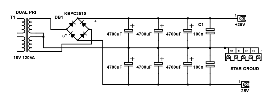
The LM3886 amplifier board would be fed with +/-25V DC. That's a split rail supply, with a +25V output, a -25V output, and a ground at 0V.
This is a simple, but conventional linear design.
As mentioned, a 2x18V transformer provides the low voltage input AC into this power supply. This is rated at 120VA. It's big enough for the stereo amplifier, but not so big that it needs a soft start or any mains DC blocking.
The two secondary coils are connected in series, allowing a 0V ground connection to be made where the two coils join. The remaining ends of the coils (forming 36 V AC) connect to the bridge rectifier.
This rectifier gives a 50V potential difference output. The + is connected to the positive rail of the split power supply, and the - to negative rail. The 0V centre tap formed by joining the two coils at the transformer creates the ground rail of the power supply.
Three 4,700µF capacitors, in parallel are then connected between the positive rail and ground, and another three between the negative rail in ground. Note that the capacitors are polarised electrolytic capacitors, where + goes in the positive rail for the positive supply, - in ground, and on the negative supply you must remember to put the + lead in ground, and - in the negative rail.
The three capacitors are also bypassed with a 100 nF capacitor (soldered underneath the board) on each rail.
That is essentially it. The supply rails (after the capacitors) can then be taken to the amplifier.
For safety, the ground of the PSU must be connected to the household earth. This is to ensure that any fault causing mains voltages to appear on the amplifier side, the household mains protection cuts the power immediately, preventing harm from the human user.
To proactively keep any chance of hum being introduced though by earth loops to any other part of my system (such as the PC), a loop breaker is introduced.
This consists of two large diodes, which will conduct the mains fault above a certain voltage, a resistor which will limit the low voltage hum inducing currents, and a capacitor to snub any other interference on the amplifier ground to the mains earth.
It's a technique described in detail at the ESP site, and I've used it in all my builds.
Preamplifier power supply
This power supply drives the op amps on my preamp. As there are only three, I kept it from being complex and it is therefore daisy chained onto the end of my main power supply output.
Since this power supply is only +/-25V, it can feed 7815 and 7915 voltage regulators (giving +/-15V) directly. 7812 and 7912 will also work, giving +/-12V but the +/-25V input voltage is quite a large difference and given linear regulators dump the additional voltage as heat, using +/-15V ones will therefore create a little less heat.
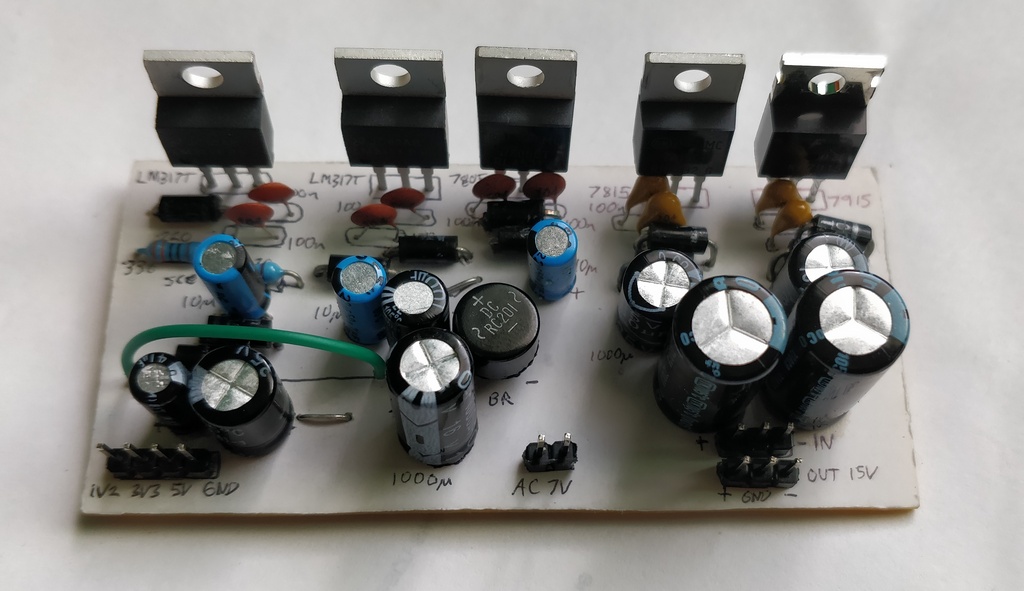
The preamplifier power supply is integrated on the same PCB as my low voltage regulators, but isn't linked to them directly. Therefore it has its own input (+25V, -25V and ground) and output (+15V, -15V and ground). Smoothing capacitors are included before and after the regulators and protection diodes. The design is based on the original ESP project 05.
There is a better project 05A/05C, using LM317 and LM337 regulators, but I didn't have many of them to hand, and given the simplicity of the preamp, it's not necessary when 7815/7915 work fine too.
Low voltage DAB/Control power supply
I located the low voltage power supply on the same board as my preamp power supply.
For this power supply, I needed +3.3V, +1.2V and +5V to drive the DAB module.
The DAB module mainly works off +3.3V, and this is what the logic levels are based on. Because of this, I would use +3.3V for the rest of my components too; the PIC microprocessor and the LCD (OLED) display.
The module also needs a +1.2V supply too though, and (although I'm not certain it's needed) it has a voltage detection which was based on the +6V input power supply or batteries used to power the original radio. I decided to implement a +5V regulated supply for this too, which I would need anyway to drive my 5V relay.
All of these regulators are connected to a 7V 3.2VA toroidal transformer, which gives just enough current to supply the system. After rectifying to DC including the diode voltage drops, it should give around 7 to 8V DC for the regulators.
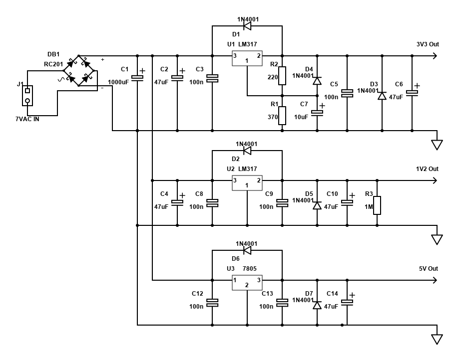
The 5V supply was simple, just use a 7805 regulator. I had quite a few spare.
The 3.3V supply I had no direct voltage regulators for, but you can easily build one with an LM317.I used 370 ohms and 220 ohms for R1 and R2 in order to configure 3.3V output.
Likewise 1.2V supply is the same, and it can be built with an LM317 which is right at the very limit of the minimum voltage this regulator can generate. In this configuration, pin 2 can be connected straight to ground, though I found you need to load it a little for it to work otherwise it measured random output voltages on the multimeter. To solve this, I put a 1M ohm resistor across the output.
Power amplifier LM3886 ESP Project 19
The power amplifier needs to be a stereo amplifier (mono sound on many radios is just not acceptable to me) and capable of driving 6 to 8 ohm hifi speakers.
This previous amplifier (which didn't have a built in radio) was a TDA2030 amplifier, and it was perfectly fine for my needs, however it did lack that extra driving force. Realistic output from this amplifier would have only been about 7W per channel.
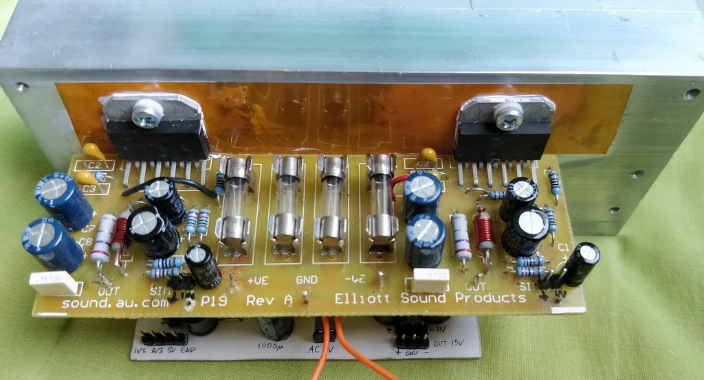
I did have an LM3886 amplifier though, based on ESP project 19, which I originally used in my main hifi amplifier but later upgraded to a more recent revision of the same project from the ESP. See ESP - Project 19 for details and schematic.
The LM3886 is capable of more than 60W, if driven to its limits. The typical power supply for this amplifier would be +/-35V but my 18V transformer would only provide +/-25V.
With this voltage supply, the output of the LM3886 is limited. Into 8 ohms, it should make 30W, or up to 40W into 6 ohms. With efficient speakers that you're not sitting far from, that's enough to be very loud!
My choice of the LM3886 though is purely because I had it already, though it is a very good sounding amplifier. You could consider smaller or larger alternatives though, including class D variants.
The LM3886 needs a good heatsink. For a pair running at +/-25V voltage it should be 1°C/W or less. I purchased the largest I could mount on the back of my case, although it was not actually rated and I had to trust my eye experience on whether it is good enough. When it comes to heatsinks, they are never too large!
The P19 PCB has been modified slightly to introduce a hum braking resistor, using the same technique as I did in my main 5.1 amplifier.
The LM3886 chips themselves are mounted carefully to the heatsink. Since they are LM3886T chips instead of the LM3886TF, this means that their metal tab needs to be isolated from the heatsink itself.
This is because the heatsink is mounted to the case, and therefore electrically connected to earth, but the LM3886 tab is connected to -35V.
In order to electrically isolate the amplifier chips, but provide good heat conduction, I used kapton tape with non conductive thermal compound (i.e., don't use a silver based one).
Preamplifier ESP Project 97
The preamplifier I needed does not need much boost to the audio level, but one thing I didn't want to forego was tone controls. I also wanted to include a bass boost too, operating at under 100Hz. Of course a volume control would be needed too, but I was not so interested in including a balance control, mainly because I knew already I would not have enough space for one, but also I put my speakers and shelf dead centre to where I'm sitting.
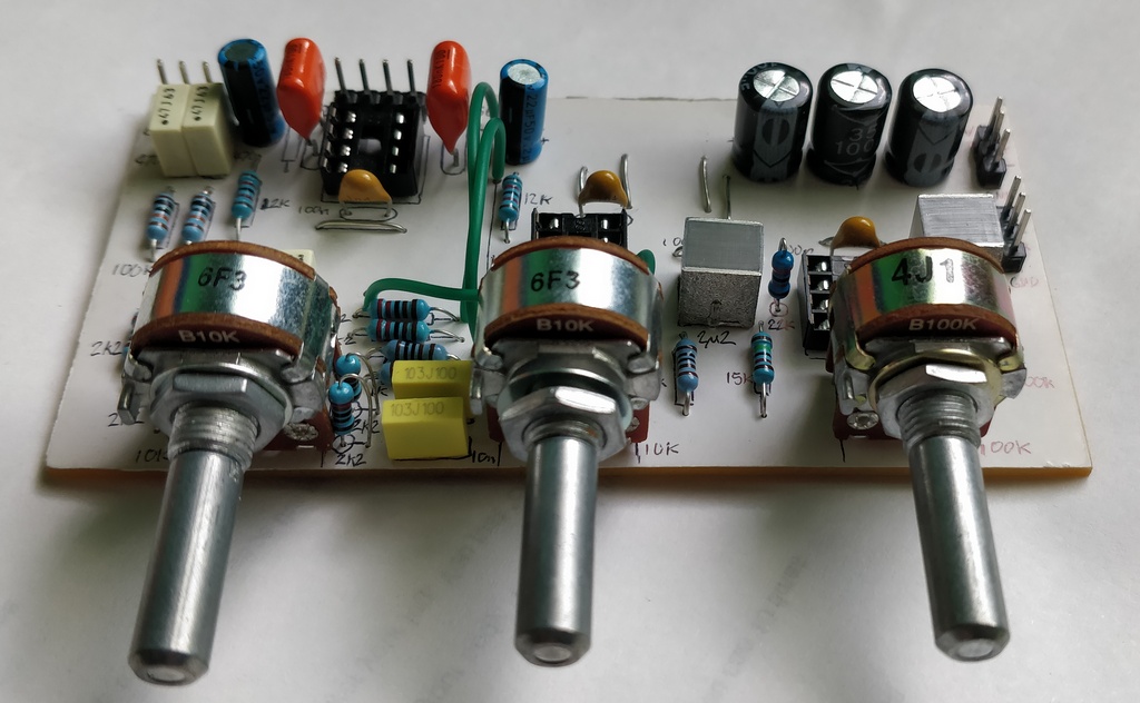
The preamp that fit my needs was the ESP project 97. As the board sold by ESP would be just a bit too wide to fit in my system though, I built my own PCB and excluded the balance control, but including an extra capacitor to add a low frequency boost on the first stage.
Since I had 10k potentiometers instead of 100k ones in my parts collection, I also substituted these instead for the tone control, and altered the value of the capacitors and resistors to have the same effect (values multiplied by x10), although for the volume control I had one 100k pot to use, so I kept that the same. The balance control was removed.
Here is one channel of my altered configuration of P97, with bass boost:
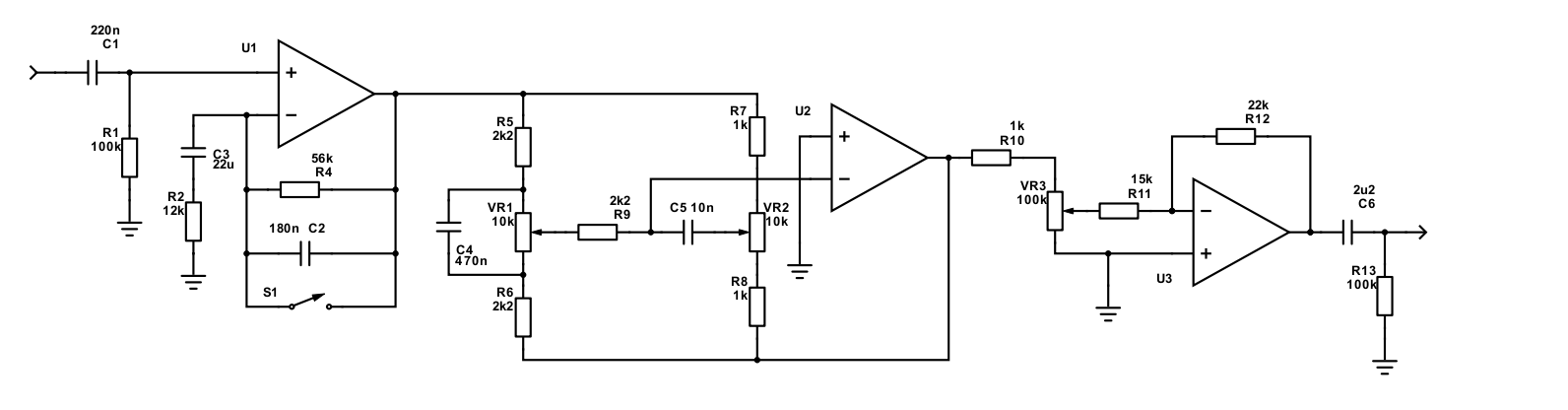
With this configuration, U1 has no gain, unless the bass boost switch S1 is open, causing it to have quite some gain at low frequencies.
Since there is no balance control, the last stage was reduced in gain.
Despite the modest gain of the preamp, the output of the DAB module and the power amplifier gain with it is plenty enough to go very loud!
Not on the preamp board, but just before it, is a rotary switch to select the audio input. I can have three:
- DAB (this is all internal)
- Line In 1 (Chromecast)
- Line In 2 (PC Audio)
- Line In 3 (Auxiliary)
Since the 4 position rotary switch has 3 poles, I used them to switch the left and right audio, and switched a 3.3V signal to either power to the DAB module, or input to three ports on the PIC microchip, so the microchip can detect what input is selected and display that on the LCD display.
References and more reading:
LM3886 Datasheet
ESP - Project 19 - Single Chip 50 Watt / 8 Ohm Power Amplifier
ESP - Project 97 - Hi-Fi Tone-Control Preamplifier
ESP - Project 05 - Power Supply for Preamplifiers
ESP - Project 05A - Power Supply for Preamplifiers (Rev A)
ESP - Linear Power Supply Design
ESP - How to Wire a Power Supply
ESP - Earthing Your Hi-Fi - Tricks and Techniques
HIFISONIX.COM - Ground Loops - design guide to minimise hum/
Mark Hennessy - Power Supply Basics
REUK.co.uk - LM317 Voltage Calculator