
DAB Digital Radio LM3886 Amplifier - Design and Construction
1 - Intro, 2 - Investigation, 3 - Design, 4 - PSU and Amp, 5 - Control Board, 6 - Software, 7 - Summary
Design and Construction
Of all my projects, I think I spent the largest amount of time designing this one.
This is because of my requirements to fit it into the 10 inch case, and I knew it would take about a month for the case to arrive from China so used the known dimensions (with a bit of leeway), and the actual dimensions of my large toroidal transformer, power supply capacitors, heatsink and P19 amp board, to draw up a 1:2 scale drawing of how the components would be placed on the inside, and how the front and back panels would look. By doing a 1:2 scale drawing, it's easy to just divide all dimensions by 2 and draw them with a ruler and compass.
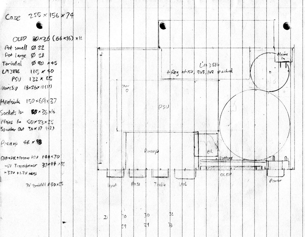
The components I had, were fixed dimensions, so I arranged the layout based on the size of these components into the overall case size of 255mm x 156mm x 74mm. These were:
- The large 120VA toroidal transformer - diameter of 90mm, height of 45mm
- The small 3.2VA toroidal transformer - diameter of 50mm, height of 25mm (I did try to originally design some PCB mount transformers I had to fit, but there wasn't enough space)
- My old PSU PCB - 132mm x 65mm
- ESP P19 rev A amplifier board - 115mm x 40mm
- Mains socket (on rear) - 50mm x 23mm x 25mm (mounted vertically)
- Heatsink (on rear) - 150mm x 69mm x 37mm
- Phono sockets (on rear) - 65mm x 36mm x 16mm
- Speaker sockets (on rear) x2 - 36mm x 17mm
- Mains power rotary switch - 18mm x 26mm x 7mm
- OLED display - PCB 80mm x 36mm, cutout for display 66mm x 16mm
- Large Aluminium Knobs - diameter 28mm
- Medium Aluminium Knobs - diameter 22mm
The design paid off, because despite the tightness of the fitting, everything did fit and work together nicely.
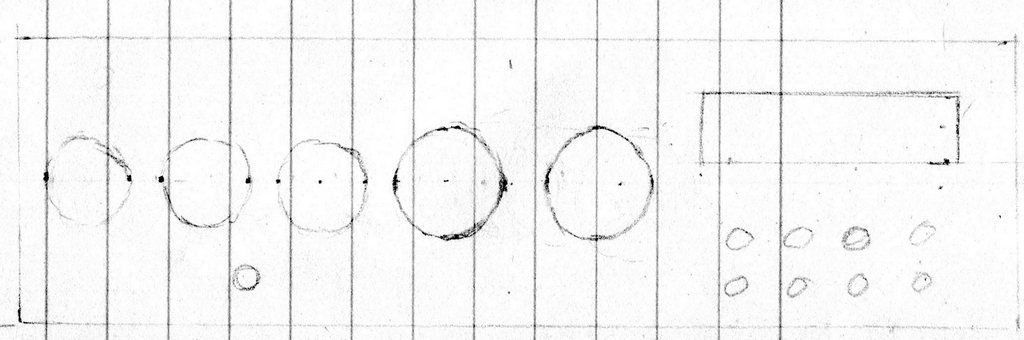
I also did a front panel design initially, and whilst I still used the dimensions from it I did move the power switch from the left side to the right side so mains leads did not cross the case internally. Actually I think the end result looks better than this drawing.
Having done the design constrained around the size of the components I did have, the PCBs I hadn't designed and built could be constrained to the dimensions I have remaining.
- Preamp PCB - no larger than 48mm x 98mm
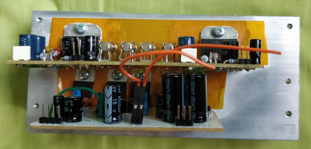
- Low voltage PSU PCB (this would sit under the LM3886 board, attached to the same heatsink) - no larger than 140mm x 70mm
- Control, DAB Module and Speaker Protection PCB (mounted vertically) - no larger than 120mm x 70mm
When designing it, I was worried about where to put the control board because this would need a fair size footprint to hold the DAB module, the large 40 pin PIC microprocessor I had, and the speaker relay. To workaround that, I mounted the board vertically, using L brackets.
I also used the height of the case and heatsink to mount both the amplifier and PSU horizontally, but one on top of the other so the area taken is just that of the larger board.
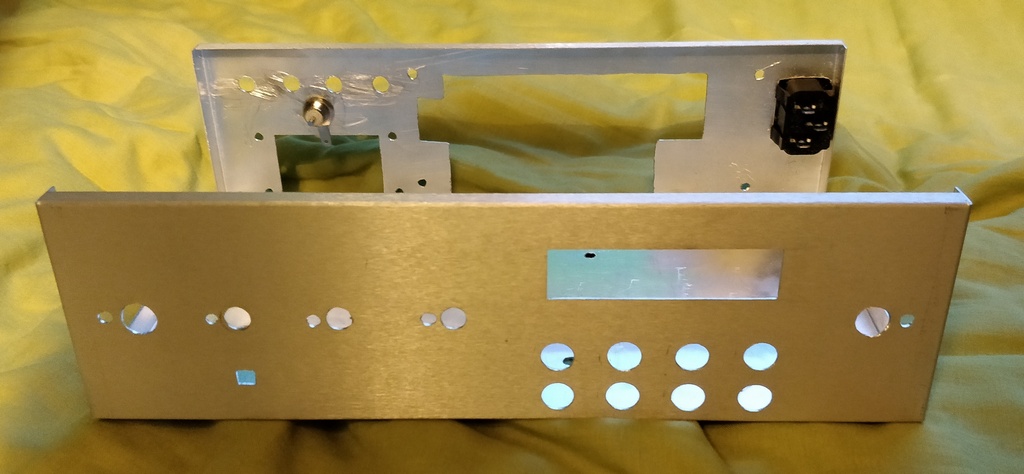
For the front of the DAB radio/amplifier, I knew the diameter of the control knobs I'd be using, and the size of the LCD display. This constrained the location and amount of controls, but it still fit together
The back was the tightest squeeze. Most is occupied by the heatsink, but I still had to mount a mains connector near the transformers, and on the other side 4 speaker connectors (+ and - for L and R), 6 phono sockets and an aerial connector.
With designs that are tight like this one, you have to think about not only the area, but the volume taken by every component. This includes switches and all, not just in front but also behind the panel.
My case is also a U shape top and bottom pieces. This means the front and back can flex inward a bit when applying pressure to them. It's critical to think about this happening when the unit is powered on and the circuit boards do not short to other boards or the case sides.
During construction, I worked over several days.
The first day was very carefully marking out the exact locations of the holes to drill and the rectangles to cut. A small, and large, steel ruler helps with this, as does a set square, and a sharp pencil. The case was new so it had a protective clear film on it which I left in place during cutting.
The following day the tools came out. The case is actually aluminium, so easier to work with than steel, but still with only handheld tools getting holes drilled in the exact location you marked and punched can end up a millimeter off, or slightly off round for large holes. Stand drills and a proper workshop would make it easier!
To get around this, I drilled smaller than I needed and widened with needle files.
Cutting rectangles I did with a junior hacksaw blade in a handheld saw blade. This worked, and then I widened and straightened with the flat and square needle files.
The heatsink required quite a large cutout on the back, but once mounted it doesn't cause any strength issues of the case.
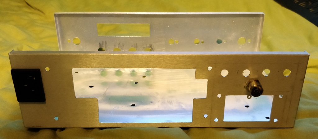
On the back the power socket I mounted to test the size of my hole. It's push fit - a deliberate choice because I didn't have enough space for the extra width of a power style one!
The heatsink was drilled with holes for case mounting, and mounting of the two LM3886T amplifier chips, and five TO220 style regulator chips. Good sharp drill bits are recommended, and then use a thread tap to create a thread for M3 machine screws.
The display and buttons PCB I did not mount with screws. This is because they would show on the front panel and spoil the look for me. Instead I got out the Polymorph moldable plastic and shaped that around the display and buttons in place. To hold the Polymorph bracket in place, I used screws in the bottom, and in the little lip at the top of the panel my case conveniently has, countersinking the holes as far as I could so the screws would not prevent the case lid from sitting nicely.
The custom bracket, though it looks awful, holds the display and buttons well, enough to survive the prodding of the buttons.
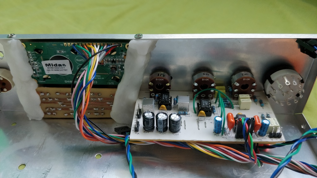
The preamp board is held just by the nuts of the potentiometers, and that's OK as it's a firm mount with three of them. The rotary input selector (right) and rotary power switch (left) also hold themselves nicely.
For all those components, I had to cut the shaft short so their knobs would fit as flush to the front panel as possible.
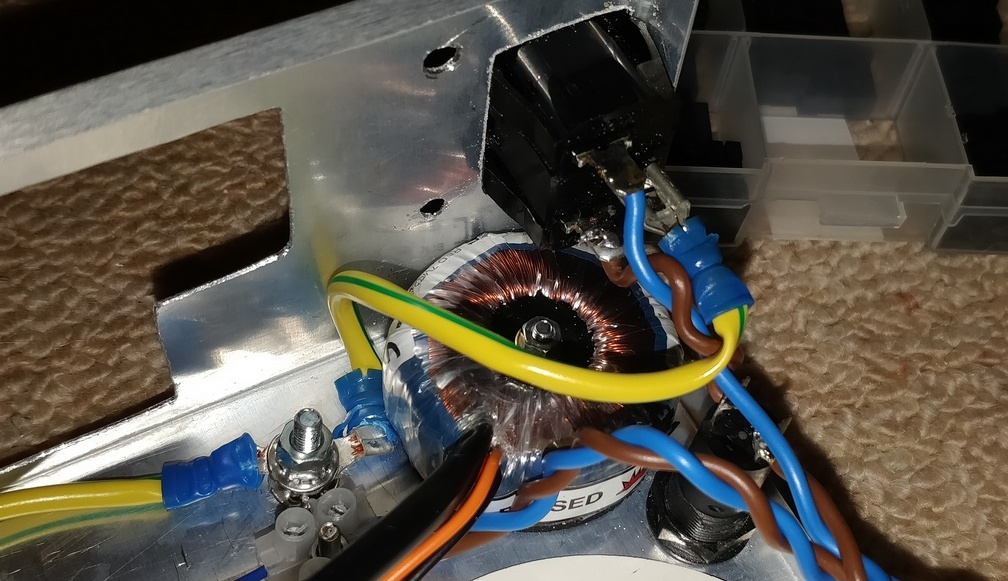
The small toroidal transformer, fuse and earth mounting point are located at the back just beneath the mains input. This keeps to a design goal of keeping mains leads as short as possible and away from audio.
The panel mount fuse holder is mounted on the bottom since I had no room on the back for it. This is OK, but meant I did have to buy some larger feet for the case than the ones it came with.
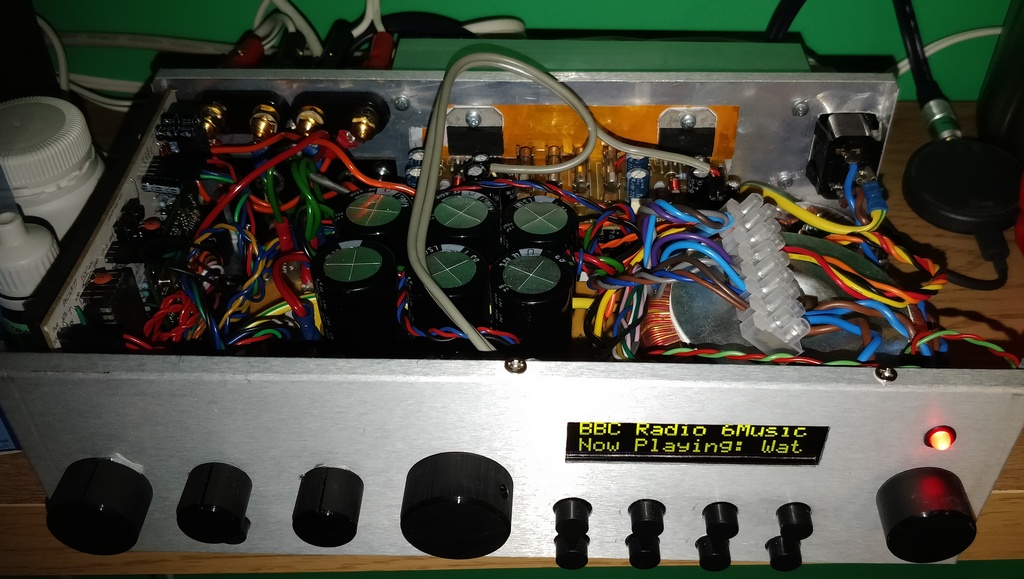
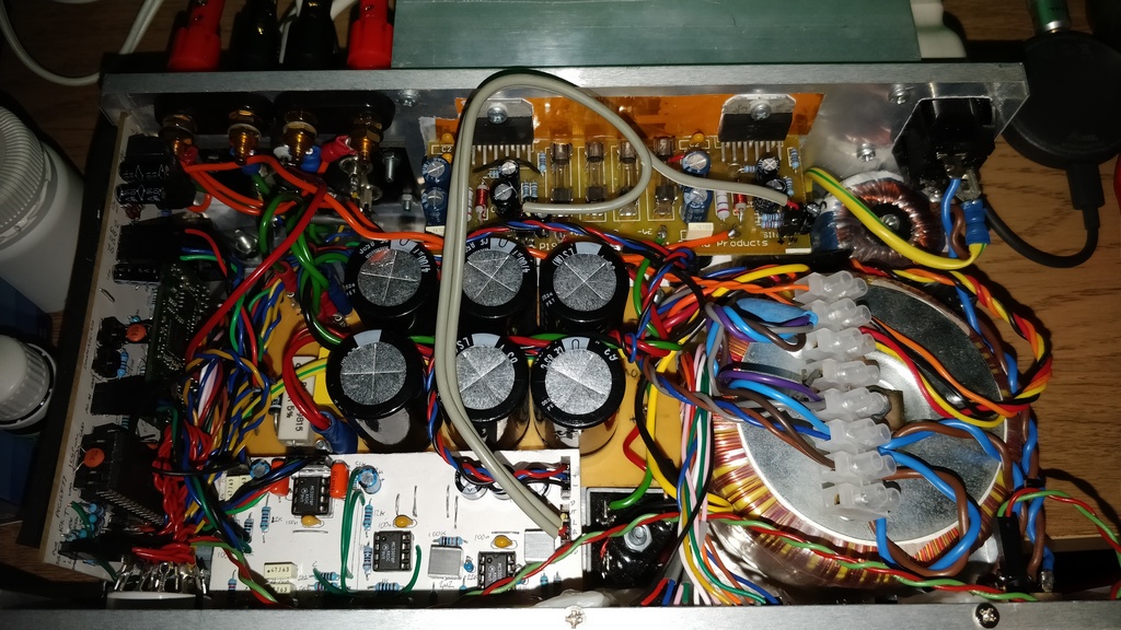
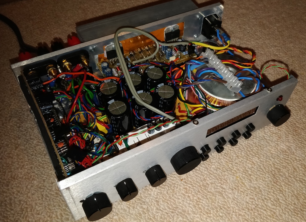
Fully assembled, you can see that it's quite packed, but despite that, it's not too difficult to dissemble and work on. Certainly easier than commercial builds these days!
- Index
- Investigating the Bush CDAB85R, Digital LCD Analysis
- Design and construction
- PSU and Amplifier
- Control Board
- PIC Software
- Summary