
DAB Digital Radio LM3886 Amplifier - Control Board and DAB Module
1 - Intro, 2 - Investigation, 3 - Design, 4 - PSU and Amp, 5 - Control Board, 6 - Software, 7 - Summary
The control board
This board would be the dock for the DAB module, and contain the circuitry for that.
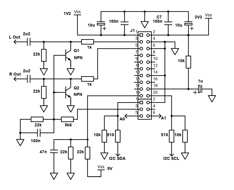
In the schematic above the connections listed:
- L Out and R Out go to the input selector switch, then the preamp
- There are VSS connections for 3.3v, 1.2v and 5v
- A0 and A1 are the connections to the buttons
- I2C SDA and SCL are the data and clock I²C lines leading to the PIC processor on the same board
This schematic is mostly a reverse engineer of the original Bush PCB, only cutting out a lot that I've no interest in.
The 3.3V on the above schematic is switched by the rotary switch, meaning this part of the circuit is only powered on when the DAB input is selected. The 1.2V and 5V inputs remain powered though, but this does no harm.
The control board also has the PIC16F77 chip, with a variety of headers to connect the inputs and outputs to.
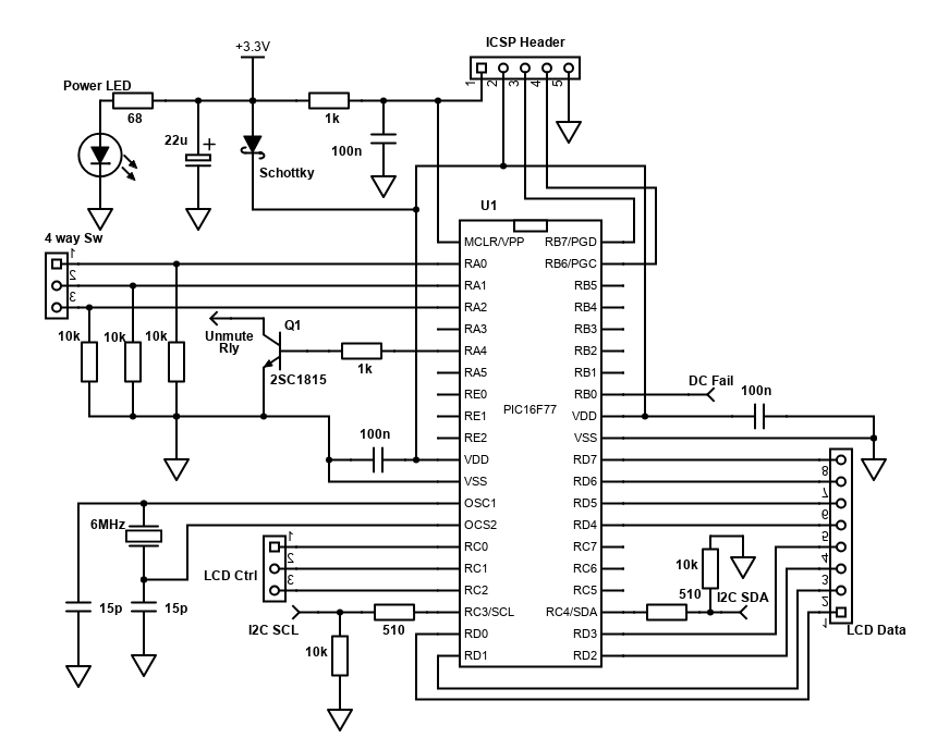
In this schematic, I've shown how I've connected my 40 pin PIC to the various I/0. Note the number of spare pins means you can definitely get away with a smaller PIC.
Although not clear on the schematic, all bypass capacitors (the 100n and 15p ones) must be as close as possible to the PIC itself.
The I²C voltage drop (150 ohm) and pull down (10k) resistors are repeated from the first diagram, but they're only needed once.
Finally, since this board would also be mounted near the speaker output terminals, I used the spare space to put an output muting relay, and DC voltage detection circuit based on ESP project 111, like how I used one in my 5.1 amplifier.
Linking off this board would be:
- Inputs for the power supply lines - 3.3v, 1.2v and 5v
- Inputs from the 8 buttons I out on a separate PCB to mount them on the front of my case
- A switched 3.3v signal to identify the active input selection (DAB, Chromecast, PC or Aux)
- A switched 3.3v line for the DAB module (so it fully powers down when other inputs are selected)
- Audio L/R outputs from the DAB module, plus ground line to the audio star ground
- An 8 bit parallel output, plus 3 wire control for the OLED display
- A power indicator LED
- An ICSP header to allow me to program the PIC
- Power amp speaker inputs and outputs for the muting and DC detection
- Plus soldered directly to the DAB module is an aerial wire
That's quite a lot of inputs and outputs! As in all my projects nowadays, I use Dupont connectors where I can as soldering wires board to board becomes hard to manage.
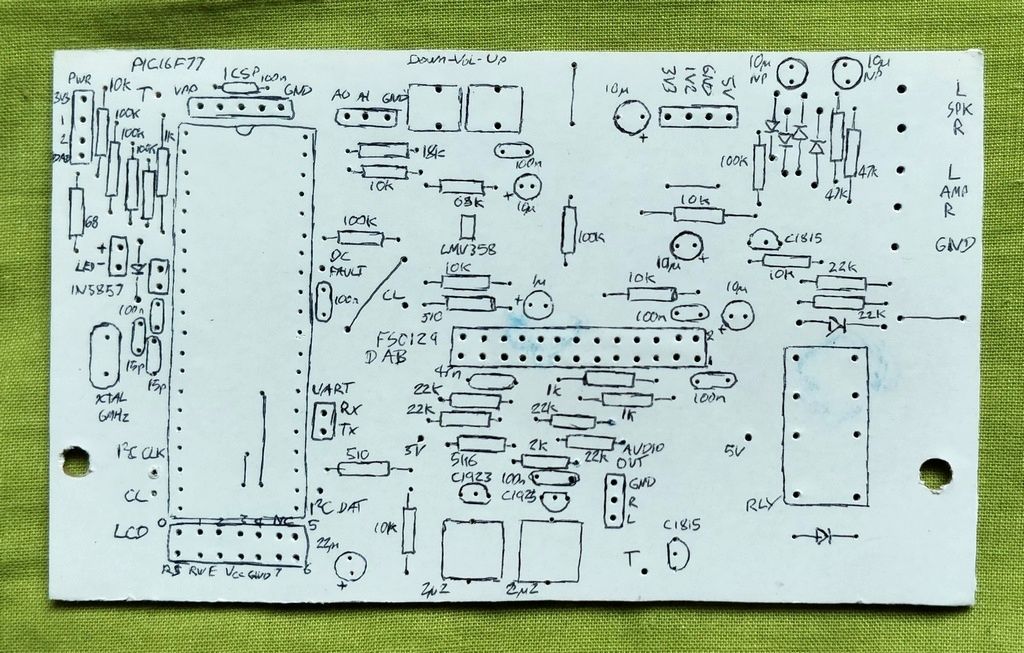
Control board PCB, before soldering components
For the full system to work, I had to do some programming of the PIC microcontroller.
Buttons board
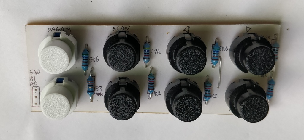
This is a small board, designed to match the width of my OLED/LCD display so it can be placed under it.
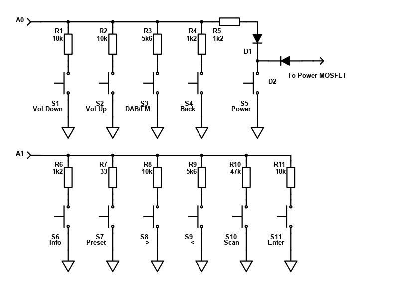
Reminder of the schematic is above, but buttons S1, S2 and S5 (and associated diodes) are not included on this board.
On this board are my eight buttons, and the required resistor values for each, again reverse engineered from the original PCB. I had these push buttons spare, but only 6 black ones so used spare white ones for a while, and then later replaced them because the difference bothered me!
References and more reading:
ESP - Project 111 - PIC Based Speaker Protection
Frontier Verona DAB Module
DAB+ Radio AEG DAB4138 reverse engineer [in German]