
DAB Digital Radio LM3886 Amplifier - Investigating the Bush CDAB85R, Digital LCD Analysis
1 - Intro, 2 - Investigation, 3 - Design, 4 - PSU and Amp, 5 - Control Board, 6 - Software, 7 - Summary
Investigating the Bush CDAB85R
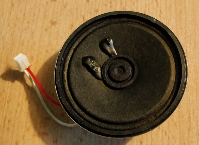
The Bush radio was made as cheap as possible. Just look at the speaker that came out! 'Tis a wonder (ツ)
The small LCD display and single sided main PCB were other clues to the cheapness, along with only a mono output.
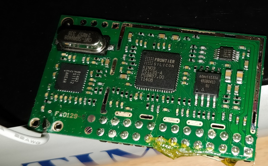
It was easy to disassemble though, and inside it, mostly air, but the interesting bit is that it contains a DAB module, the Frontier FS2052 'Verona' module, powered by the KINO3 chip.
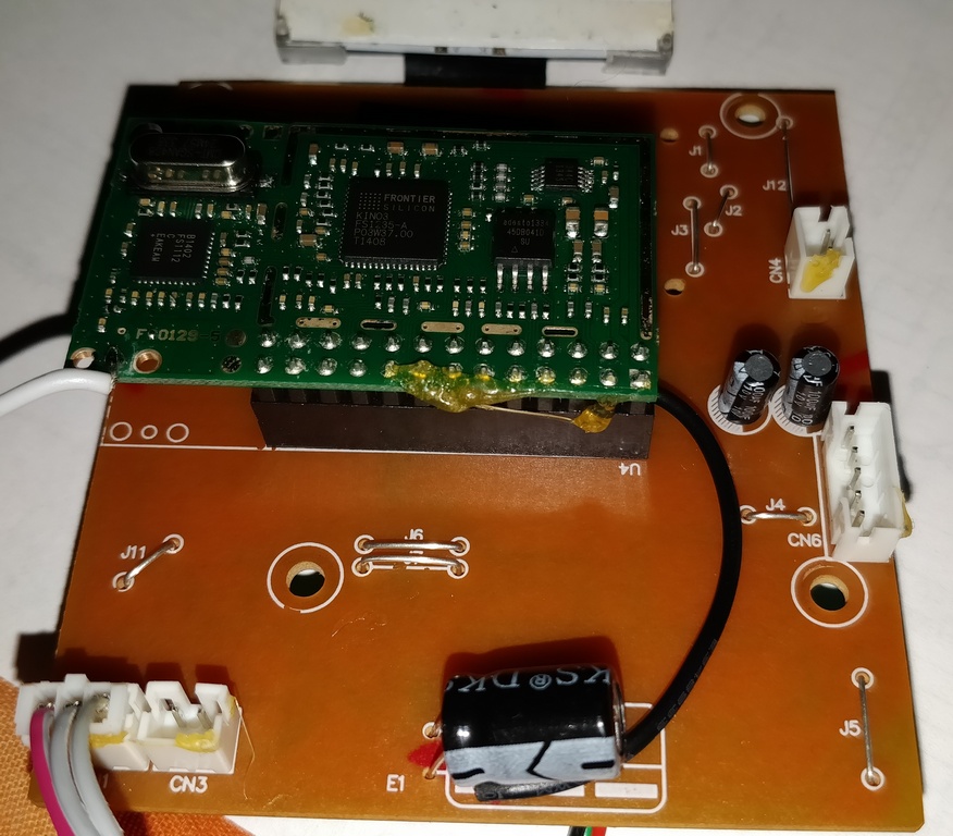
This seems to be a known chip, capable of receiving a stereo signal and sure enough when I connected some headphones directly to pins 3 and 5 of the module and tuned into BBC Radio 6, I could hear a stereo signal.
This was good news - it meant that I could use this module in my own build, so I started to plan out my design and reverse engineer the main PCB.
The module itself does not have any datasheet really, because the module firmware differs depending on the radio model it is put in.
For example, some radios may have different interfaces - more buttons, or a rotary encoder to move left/right to select stations or change the volume. Different radios can also have different LCD displays.
I found someone else had reversed engineered a schematic, available as a PDF linked from here: http://www.df7sx.de/dab-radio/
As I investigated the Bush radio PCB though, there were some differences. Whilst I did reverse engineer most of the PCB, there were a number of features I wasn't interested in and these simplified my build.
Below is a summary of the pins of the Verona DAB FS2049 module as used in the Bush CDAB85R, and whether I'd have any interest in them. This is looking at the module from the top and in bold are the pins I used:
| 3.3V supply | 2 | 1 | 1.2V supply |
| Ground | 4 | 3 | Audio Left output |
| Ground | 6 | 5 | Audio Right output |
| No connection | 8 | 7 | No connection |
| No connection | 10 | 9 | No connection |
| No connection | 12 | 11 | Backlight control - switching the negative side of the LCD backlight via an NPN transistor. Not needed for OLED display. |
| Ground | 14 | 13 | This holds the standby circuit high when the radio is activated. Since my power is 'always on', I left this disconnected. |
| No connection | 16 | 15 | No connection |
| Hooked into 3.3V via 10k resistor (appears to be different from the AEG DAB4138) | 18 | 17 | No connection |
| LCD I²C Clock | 20 | 19 | Battery/power detect pin - appeared to be connected to a two 22k resistor voltage divided which is then directly connected to the 6V power input. |
| Ground | 22 | 21 | LCD I²C Data |
| No connection | 24 | 23 | Audio mute pin |
| Button bank '1' | 26 | 25 | Button bank '0' |
So out of the 26 pins, 11 are completely disconnected in my design, and 4 are ground anyway.
This makes for a simple implementation of the PCB required.
Audio output
The audio output (pins 3 and 5) can be easily hooked into a preamp. I used the same output muting circuit as the original radio, just with my own through hole resistors and transistors, which hangs off pin 23. I figured any simple NPN transistor will do and I used some old 2SC1923 transistors.
See the main DAB module schematic for the output and muting circuit.
Buttons
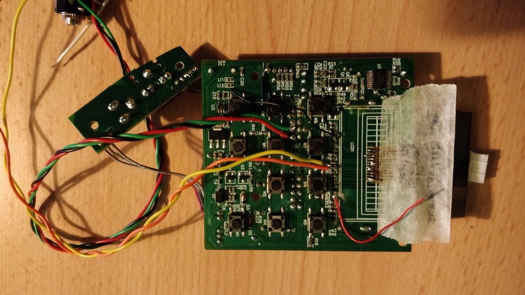
The existing buttons are PCB mounted push buttons just connected to the DAB module via resistors (R40, R41, R45, R46 in the picture).
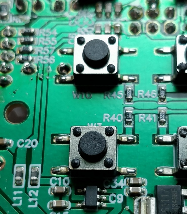
This means that the DAB module would have an ADC (analog to digital converter) connected to pins 25 and 26, and it's software program to read voltages and map them to a particular button press.
This is a clever way of handling multiple buttons with only two connections. Each button will have a resistor between it and the ground, and therefore produce a different voltage.
The Bush radio has 11 buttons, including the power one. 10 I'll be using, 8 on the front of my unit.
Below is the schematic of these buttons. Of these - S1 and S2 (Volume up/down) I'll be mounting on my control board, out of use. This is because I'll set the volume to its maximum on the initial power on. It then remembers the volume after. The real volume level will be controlled in my preamp, which uses a much nicer and precise potentiometer.
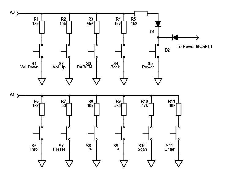
S5 and the diodes leading off it are left out completely. This is because my radio won't have a 'soft' power button. The power to the DAB module will instead be controlled through a rotary switch, when the 'DAB' input is selected.
LCD Display
The challenge though is the LCD display.
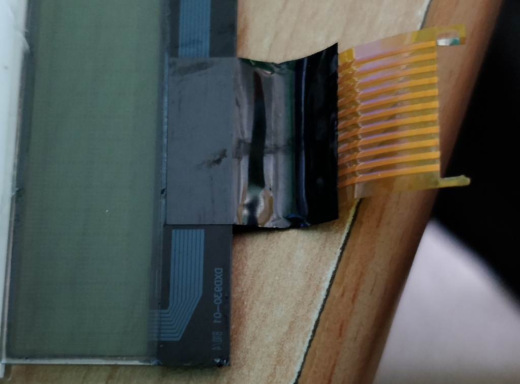
The display connected to the radio is a small chip on glass module, which has quite a number of connections via a ribbon cable. Only two of the wires carry data though.
What would the data look like though? This was my challenge. In an ideal world, I could look up the datasheet for the LCD and know the kind of communication it expects to receive. But the only numbers barely visible on the module yielded no information when trying to search around.
This was a problem. All I knew was that there were two data pins (so a serial device) because the rest of the LCDs pins were either on ground, the voltage supply or the same with a resistor or capacitor in between. Only three led to the DAB module, and one had to be the backlight, because the wire entered the side of the display instead of being on the ribbon cable..
I can't expect to buy any serial driven LCD and connect it, and also important to me was I wanted to use an OLED display because they are so much clearer to read, and look much better.
So, I planned to use a microchip to bridge the interface between the DAB module and the OLED display I wanted to use. But in order to code it, I needed to be aware of the logic the DAB module sends.
This led to me investing in a cheap USB logic analyser, the 'Hobby Components USB 8 channel 24MHz Logic Analyser'.
This, combined with the Sigrox PulseView software and my Linux desktop (also works on Windows though), allowed me to monitor the communications.
I initially tried this with the LCD disconnected - as I removed it to reverse engineer the PCB more easily. However I didn't find much, but enough to identify that the DAB module was sending some data via the I²C and was expecting a response.
The I²C protocol handles multiple devices, and the master (that's the DAB module in this case) will issue an address and wait for the slave to respond with an ACK, by pulling the data line low. It's a 'yes I'm here and ready to receive' acknowledgement.
With the LCD disconnected though, nothing more is sent by the master because the slave never said it is ready. This meant to analyse further, I'd need to re-attach the LCD. I managed this by scratching off the insulation on the ribbon cable and soldering it back on to the PCB. Bellow is an image of the temporary handiwork, the yellow and orange wires are connected to my logic analyser during testing, red and green are audio left/right, black is ground.
After analysing again, this time with the LCD connected, I now receive the data logic.
I then tried to capture a variety of events so I could read what is on the LCD and compare that to the communication sent. This included pressing the Info button so I could see how custom characters were generated.
Sigrox PulseView would read in the various signals on the two data lines over a period of time, I stopped and started the capture manually. You can then add protocol decoders, specifying which data pin is the clock and which is the data. This allowed the I²C to be decoded.
Examples of the captured communication:.
1: Capture of commands sent to the LCD on first power on
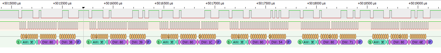
| Sequence | Address | Data |
| 1 | 3E | 80,38 |
| 2 | 3E | 80,39 |
| 3 | 3E | 80,1C |
| 4 | 3E | 80,54 |
| 5 | 3E | 80,71 |
| 6 | 3E | 80,6E |
2: Capture of a second set of commands sent to the LCD on first power on
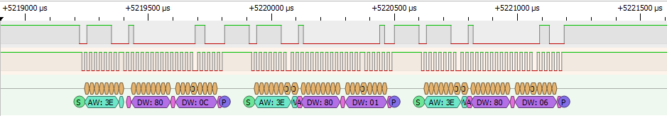
| Sequence | Address | Data |
| 1 | 3E | 80, 0C |
| 2 | 3E | 80, 01 |
| 3 | 3E | 80, 06 |
3: Capture of the welcome message, first line
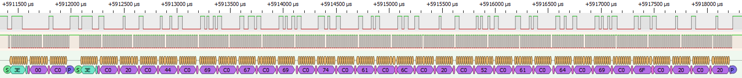
| Sequence | Address | Data |
| 1 | 3E | 00, 80 |
| 2 | 3E | C0, 20, C0, 20, C0, 20, C0, 57, C0, 65, C0, 6C, C0, 63, C0, 6F, C0, 6D, C0, 65, C0, 20, C0, 74, C0, 6F, C0, 20, C0, 20, C0, 20 |
4: Second capture of the welcome message, second line
| Sequence | Address | Data |
| 1 | 3E | 00, C0 |
| 2 | 3E | C0, 20, C0, 44, C0, 69, C0, 67, C0, 69, C0, 74, C0, 61, C0, 6C, C0, 20, C0, 52, C0, 61, C0, 64, C0, 69, C0, 6F, C0, 20, C0, 20 |
The key points I took away though is that many of the functions are similar to the setup of HD44780 based LCDs.
What's different though is the sending of the characters. Each normal ASCII based character (or custom character address) is preceded with the code 0xC0.
This is visible when you look at the 3rd and 4th captures above.
Remove the C0 characters from the 2nd sequence of each data message, you get this result:
20, 20, 20, 57, 65, 6C, 63, 6F, 6D, 65, 20, 74, 6F, 20, 20, 20
20, 44, 69, 67, 69, 74, 61, 6C, 20, 52, 61, 64, 69, 6F, 20, 20
Translated to text:
   Welcome to
 Digital Radio
Nice - this is exactly what is displayed on the LCD.
On the first set of functions, I believe these to be (on a standard HD44780):
- 80,38 - 38 function set
- 80,39 - 39 function set, why again?
- 80,1C - 1C 0001 1100 cursor/display shift, S/C=1, R/L=1 Shifts the entire display to the right. The cursor follows the display shift
- 80,54 - 54 0101 0100 Set CGRAM Address?
- 80,71 - 71 0111 0001 Set CGRAM Address?
- 80,6E - 6E 0110 1110 Set CGRAM Address?
Not all of them make sense. I assume the first command 80 tells the LCD to expect a function command to be processed next.
On the second set of functions:
- 80,0C - 0C 0000 1100 Display On, Cursor Off, Blinking Off
- 80,01 - 01 0000 0001 Clear display
- 80,06 - 06 0000 0110 Entry mode set, DDRAM Address is incremented by "1" when a character code is written into or read from the DDRAM (i.e. fill text in from left to right)
These make sense compared to the HD44780.
When it comes to custom characters, these are generated as so:
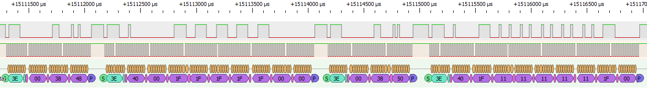
| Sequence | Address | Data |
| 1 | 3E | 00,38,48 |
| 2 | 3E | 40, 00, 1F, 1F, 1F, 1F, 1F, 00, 00 |
| 3 | 3E | 00, 38, 50 |
| 4 | 3E | 40, 1F, 11, 11, 11, 11, 11, 1F, 00 |
This is two examples, which translates as below:
Char 01 or 0x48
| 00 | |||||
| 1F | |||||
| 1F | |||||
| 1F | |||||
| 1F | |||||
| 1F | |||||
| 00 | |||||
| 00 |
Char 02 or 0x50
| 1F | |||||
| 11 | |||||
| 11 | |||||
| 11 | |||||
| 11 | |||||
| 11 | |||||
| 1F | |||||
| 00 |
Using them is just like using normal characters, except their codes are 01 and 02:
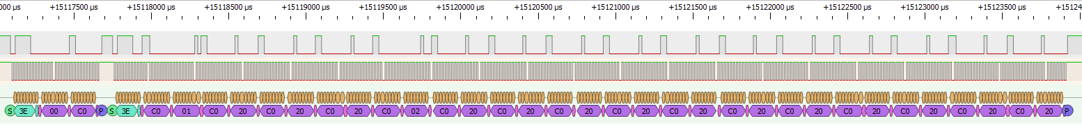
| Sequence | Address | Data |
| 1 | 3E | 00, C0 |
| 2 | 3E | C0, 01, C0, 01, C0, 20, C0, 20, C0, 02, C0, 20, C0, 20, C0, 20, C0, 20, C0, 20, C0, 20, C0, 20, C0, 20, C0, 20, C0, 20, C0, 20 |
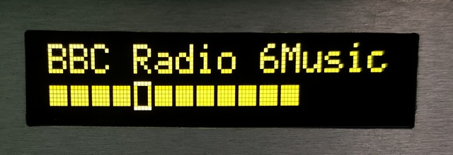
The intention is to display a slider showing the signal quality, with the second character indicating the minimum quality for a good signal, and the first character showing how far along the signal quality is.
I didn't have an aerial connected during the test, hence the poor signal quality but the empty space is just filled with the standard space character (hex code 20). Again removing the C0 characters, gives this sequence.
01, 01, 20, 20, 02, 20, 20, 20, 20, 20, 20, 20, 20, 20, 20, 20
▮▮ ▯
It's then perfectly valid on a HD44780 display. Here's a view of a similar result on my new OLED display (post build):
Entering the custom character creation mode with codes 48 and 50 for the first and second characters is also valid, but the code 38 that occurs before is not necessary.
Overall, even though the serial communication is quite close, I couldn't find any other LCD or I²C driver that expects this kind of communication, so couldn't guarantee any display I buy may be directly connected to the DAB module and work fine
Therefore, I decided I would code my own microchip which would translate the received data from the DAB module, and send out to a normal HD44780 based OLED display (connected via a parallel 8 wire + 3 control interface).
Having my own microchip also allows me to extend the features, such as speaker protection and using the LCD to display any other input that is selected besides the DAB.
The choice of microchip I wanted to limit to what I already have. Given the simplicity, a PIC16F827A could have been fine, but the PIC18F77 I preferred to use as it includes a hardware I²C compatible module in it.
The timing of the above I²C communication is one clock pulse (high + low) as 50kHz / 20us. That's a standard I²C speed, so PIC processors with built-in support will all work fine at this speed..
If you're buying your own PIC though, you can choose a smaller version as there is no need for a big 40 pin microchip.
References and more reading:
Sigrox PulseView software
Frontier Verona DAB Module
DAB+ Radio AEG DAB4138 reverse engineer [in German]
Rundfunkforum - DAB modules: advantages and disadvantages, differences,
distribution [in German]
- Index
- Investigating the Bush CDAB85R, Digital LCD Analysis
- Design and construction
- PSU and Amplifier
- Control Board
- PIC Software
- Summary