
TDA7439/STA540 Amplifier - a small yet high quality amplifier
Part 1 - intro and hardware, Part 2 - software, Part 3 - conclusion
Part 3 - Conclusion
Conclusion
This build was basically an excuse to use the STA540 amplifier module I built (which I think itself was an excuse to build this amp!) and look at the TDA7439 as a simple digital driver for the audio input side of it.
It was supposed to be low time and low cost, but I ended up spending more time and cost due to the PCB rebuild and power supply design revision.
I'm really happy with it now though. Whilst it's not as serious as my Hi-Fi LM3886 5.1 channel amplifier or my TDA1514/TDA2040 Surround Sound Amplifier, or even my DAB Digital Radio LM3886 Amplifier, it's still really impressive.
The difference between this and the others is it's really small, yet still packs a punch. It's small due to the STA540 and TDA7439 chip, the completely IR remote driven control and the DC power supply, of which is part external and part internal using isolated DC-DC convertors in a new experience for me.
Because mains electricity is kept away from the unit, this makes it somewhat beginner friendly as a potential first 'semi-serious' amplifier build. Custom PCBs are required however, but if you're interested just replicate my scanned drawings with etch resist pen and etch single side copper board (tips are at my PCB Building Guide) or go better and order a professionally made board if you like!
It's also the quietest amplifier I've ever built. Whilst I strive to make all my amplifiers quiet, this one is dead silent beyond what I expected, even without hum breaking resistor tricks. Sound quality is excellent.
Pictures
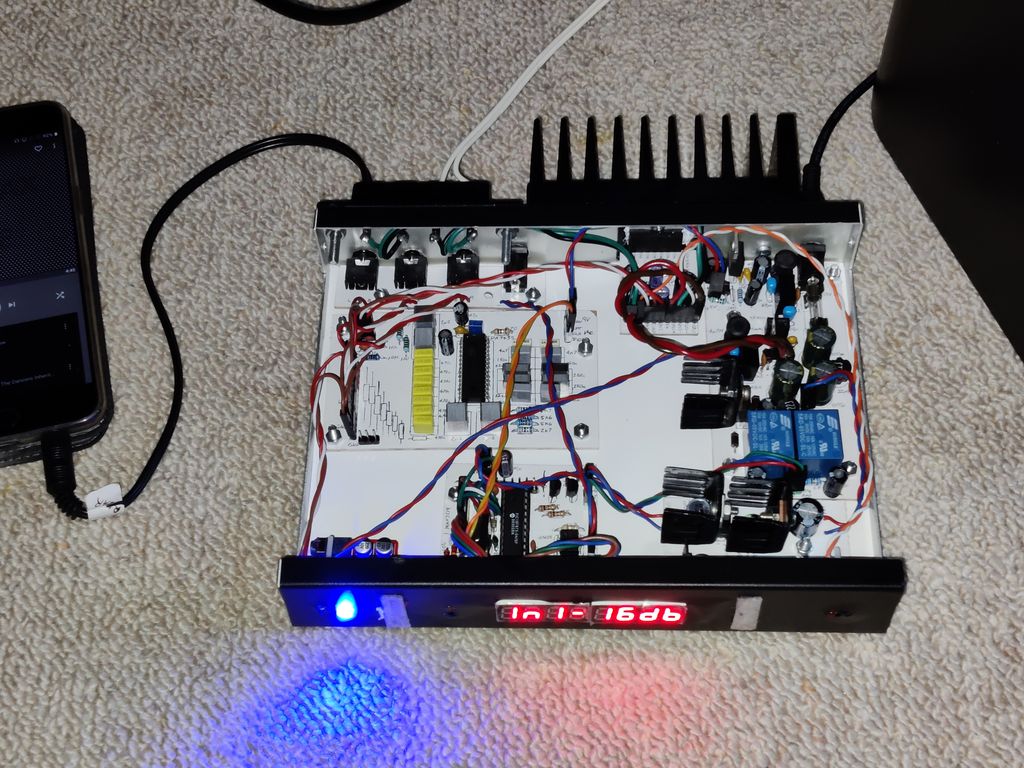
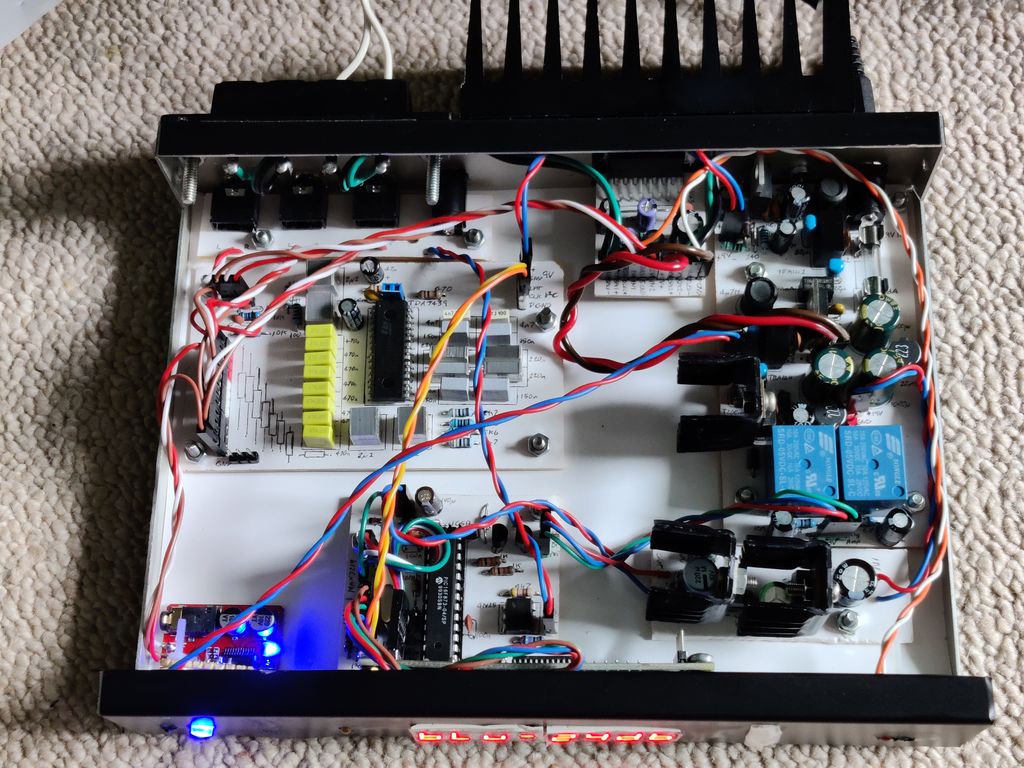
Above: First test, covers off
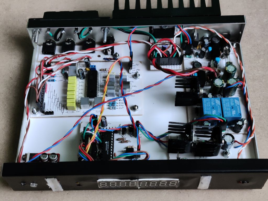
Above: View with cover off. From top left clockwise: Input jacks board, STA540 board attached to heatsink, PSU board with isolated 9V
and 5V outputs, 5V linear regulator board for logic, control board (PIC microcontroller), Bluetooth audio module (just visible bottom left),
and middle left is the TDA7439 board
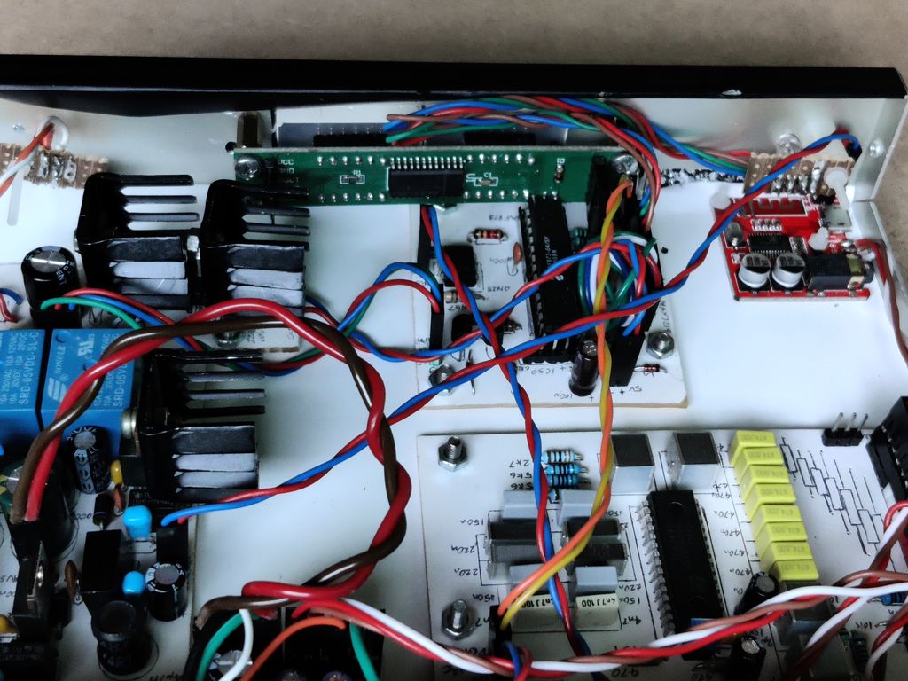
Above: View of cover off from the back. This shows the MAX7219 LED display module (top middle), control board (middle) and clearer view
of the Bluetooth audio module (top right). Also visible are the RGB LED (top right, mounted on stripboard) and the fault LED (top left, again
on stripboard)
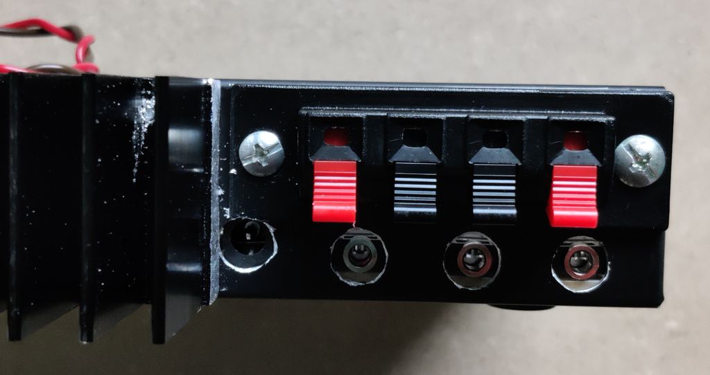
Above: View of back showing (left to right) USB 5V trigger DC jack, stereo 3.5mm inputs jacks 3 to 1, with spring clip terminals for
left/right speaker output.
Above: Another view with cover off, operating with Bluetooth audio selected
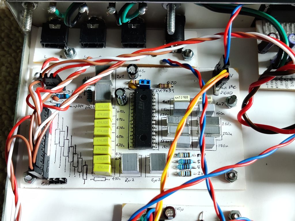
Above: Closer view of the TDA7439 board, and inputs jacks board
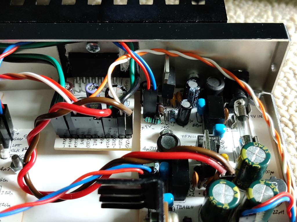
Above: Closer view of the STA540 board, and some of the PSU. The top viewable part of the PSU is the 9V regulator and 12V isolated DC-DC
converter feeding into that. On the far right as the input jack, fuse, coil and capacitors
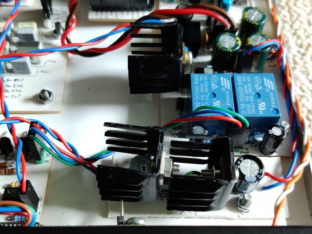
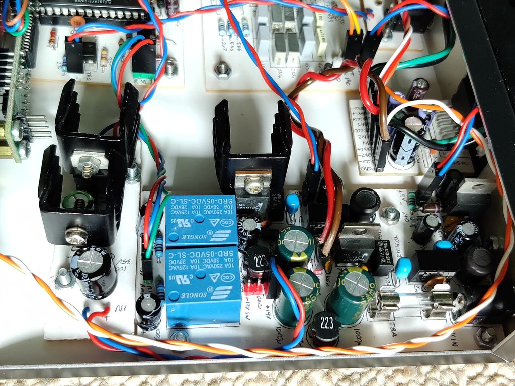
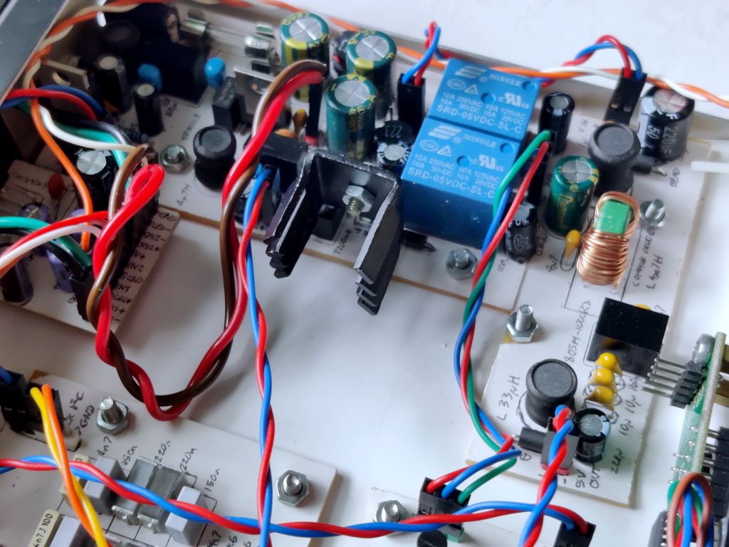
Above: Closer view of the rest of the PSU. This shows the blue power relays (right is for main power, left for Bluetooth module power).
The regulator with the heatsink at the top middle is the 7812 regulator dropping 19V to 12V for the 12V to 5V isolated DC-DC convertor which
powers Bluetooth. The two heatsink regulators at the bottom are a 7812 (right) followed by a 7805 (left), dropping 19V to 5V for the control
logic (PIC, display, LEDs etc). Having the regulators in series drops the heat.
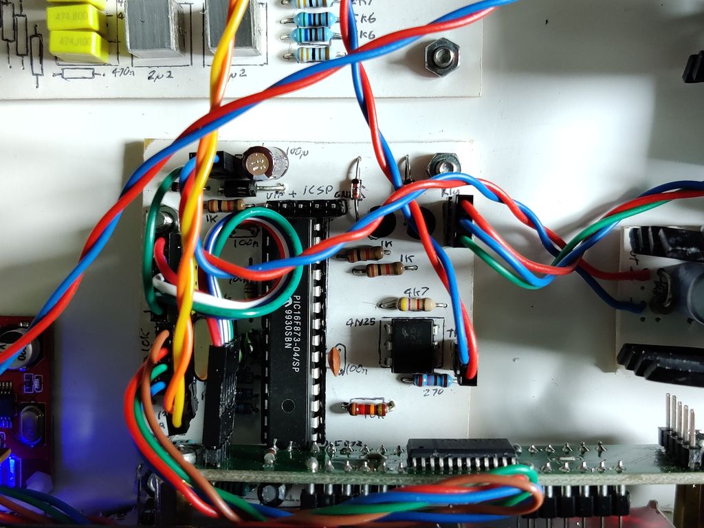
Above: Closer view of the control board, partially obscured by the MAX7219. It was tight to mount the two close to each other and yes,
the crystal does get in the way of the MAX7219 header! The control board needs to be tight to the front of the unit because the IR receiver
and indicator LED are mounted on this board.
Above: Another closer view of the PSU board, viewed from the side.
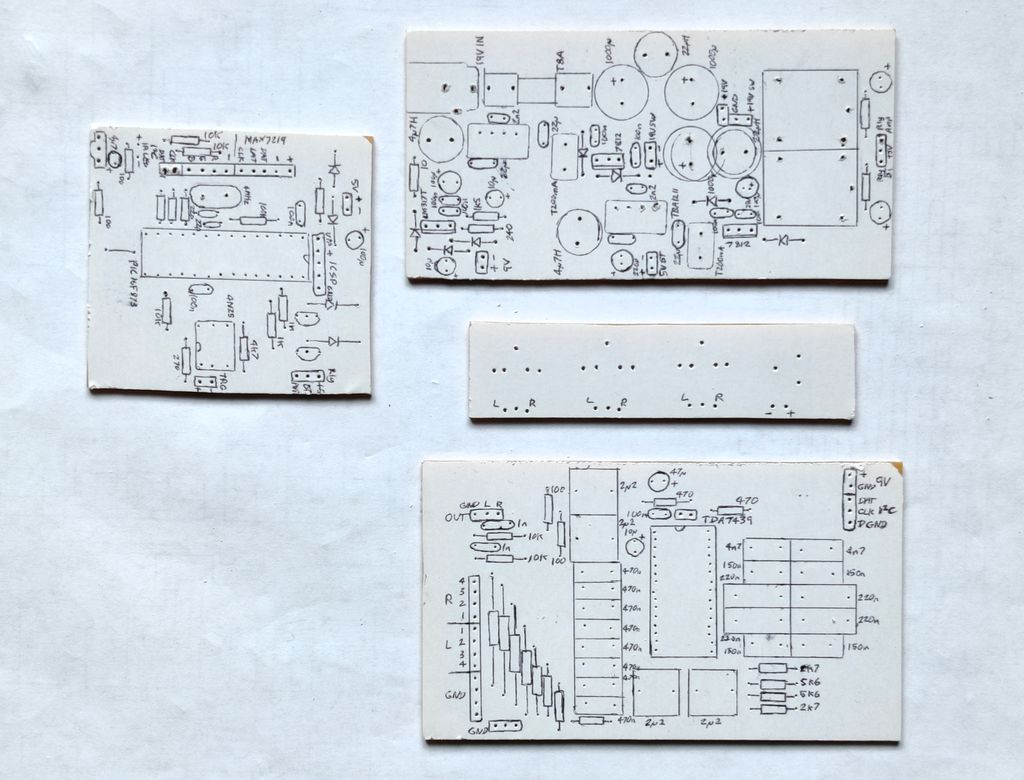
Above: PCBs with reversed design print out prior to drilling.
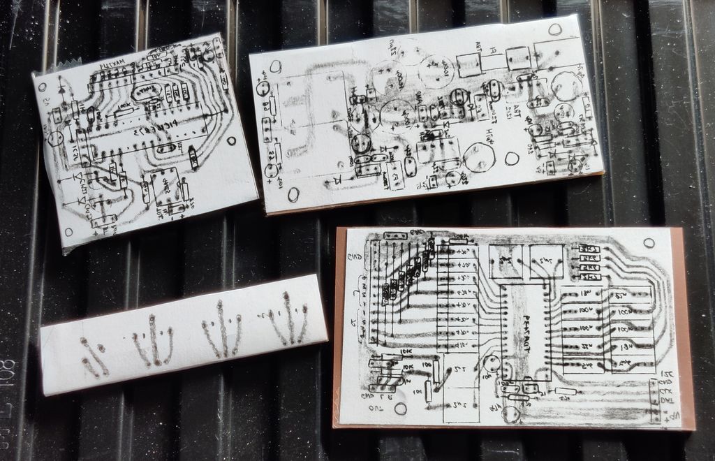
Above: PCBs with drawn layouts prior to etching.
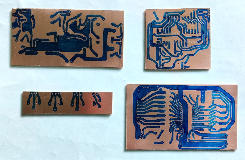
Above: PCBs with marked overlay prior to soldered.
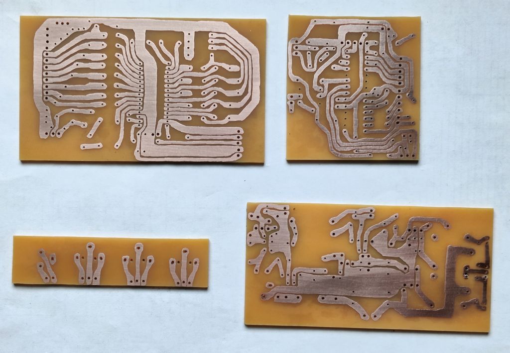
Above: PCBs copper underside prior to soldered.

Above: PCBs after soldering.
Update: Some updated pictures with the new 5V PSU board:
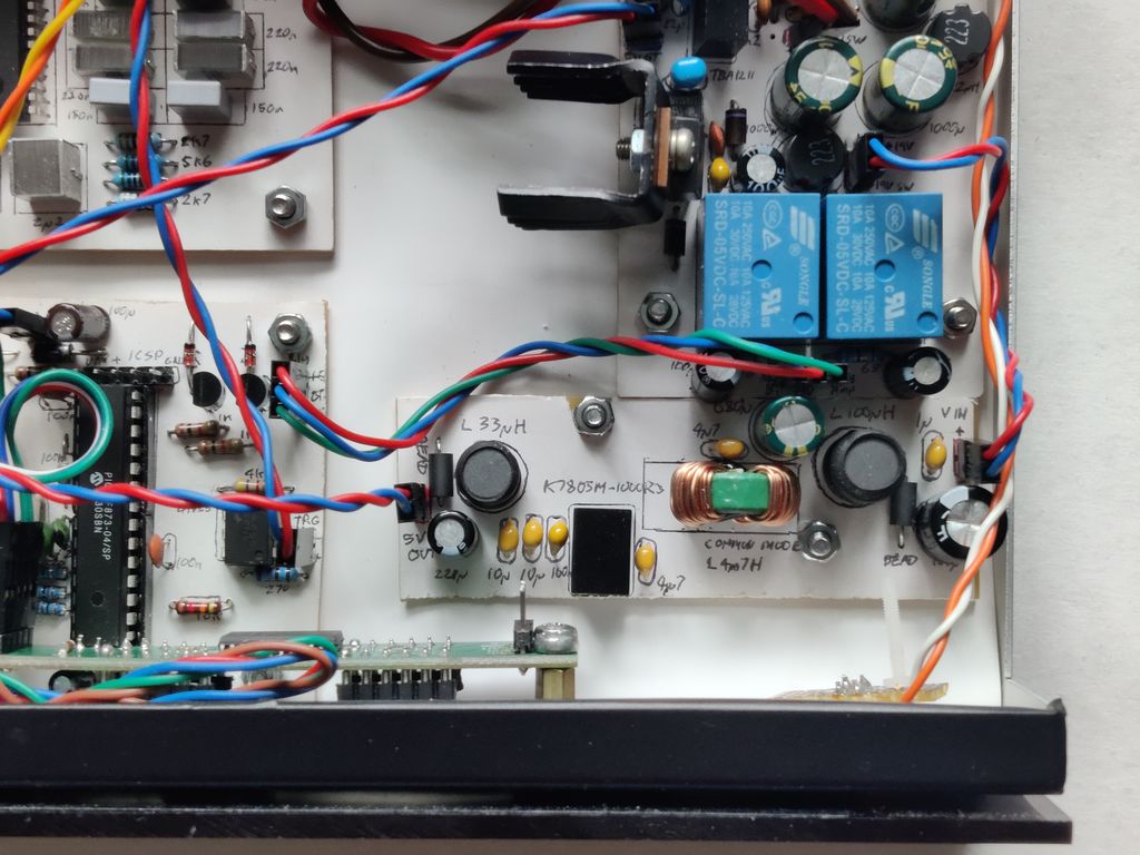
Above: View of the K7805M-1000R3 5V PSU board, with all its filter components, in place of the original switching PSU board.
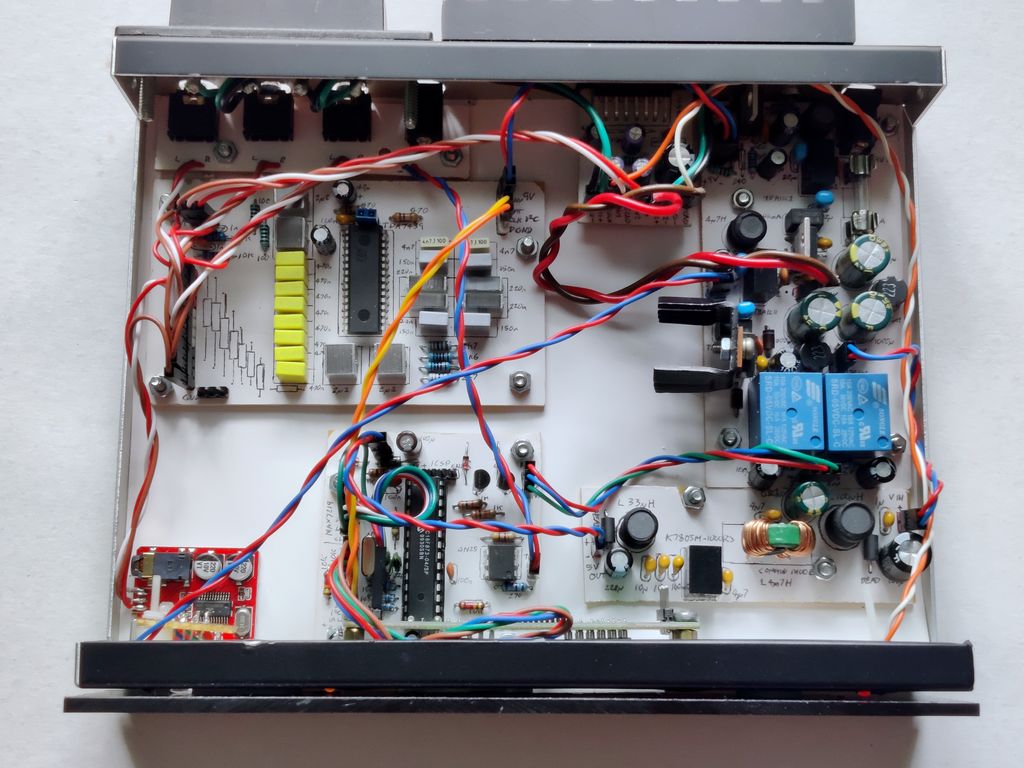
Above: Overall view with the new PSU in place.
Above: Another view of the 5V PSU board and main PSU board