
150W Subwoofer
Contents
Page 1 - Design
Page 2 - P3A Amplifier
Page 3 - Input filter and EQ
Page 4 - Power Supply details
Page 5 - Box Design
Page 6 - Box Construction
Page 7 - PIC Micro Control
PIC power control
It may seem a little excessive, but since I had the programmer, the C compiler and some spare PIC16F627 chips, this solution to handling power on mute, 12V trigger powering and LED for status would be small, reliable and cheap.
Three relays would be involved.
- Mains switching relay, to switch in the 225VA toriodal transformer
- Output switching relay, to disconnect the speaker from the amp
- Input switching relay, to remove any input so the output switching relay switches a very small current, prolonging its life (thanks to Mark Hennessy for this idea).
Two LEDs would be on the front of the box. One LED for standby, one (blue) LED for power on. The would both flash in turn when the power on sequence runs.
Finally, there would be two inputs. One small push button for mounting on the front of the case for manual power on/off, and one 12V trigger input, isolated using a standard opto-isolator in order to prevent earth loops.
Thats all there is to it. Without the PCB mount transformer, the PCB turns out pretty small. It has been desgined to fit my relays (and other components) I had available to me, but is provided as a scan below if you want to use (and modify it in your subwoofer/power amplifier project. The C file, and HEX file for the PIC micro is also provided.
Schematic
PIC Control Schematic
The control circuit is not too difficult to contruct, and I managed to fit it all onto a PCB measuring 8cm x 5.5cm, including relays and voltage regulator.
Switch S1 is a simple push-to-make switch. Should be easy to find and cheap. This is the power switch and will be on the front of the subwoofer with the two indicator LEDs.
Switch S2 is a slide switch. In one position, the circuit acts as a power control for using the power switch. In the other position however, the power switch gets disabled and the 12V trigger input gets enabled. This allows the subwoofer to be turned on and off externally using a 12V trigger, such as one from a preamp.
Relay switching transistors are standard NPN transistors, and not too critical. I used the very common C1815 and that works fine. The diode across the relay is required or the Back EMF from the relay coils will destroy the transistor. The diodes D5 - D7 are standard 1N4148 diodes.
LEDs are standard. I used a blue one for power, and red for standby, but any colour you choose would work fine, just as long as it is a standard type.
The opto-coupler is used to isolate the 12V input from the circuit, eliminating any potential earth loops and should be easy to get.
Finally, the circuit above is designed to take a 12V input, which powers both the relays and the PIC. The PIC supply must be regulated and a standard 7805 or 78L05 would work fine as 5V current draw will not be higher than 100mA.
12V PSU Schematic
Above is the schematic for a simple 12V PSU. It need not provide more than 0.5A of power, so a standard 6VA transformer is fine, and can be PCB mount (if you want).
Fuses are included for both transformers, and the mains power relay is also in this schematic, as it is less danagerous to run 12V wires from the control board to the PSU board rather then running high current, high voltage mains wires to the control board!
This requires mains wiring, so:
This power supply requires live mains wiring. Please do not construct it unless you are suitably qualified. Death or serious injury can result!
The rectifier is very simple, and the small 100uF cap will allow the supply to fall quickly if the mains is cut, causing the relays to disconnect quickly.
RLY1 must be rated for 250V AC use, and able to handle 10A current switching in order to cope with the high inrush current caused from the 225VA toriodal
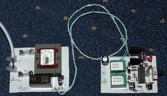
Control and PSU PCBs
The picture above shows my boards completed and with the PIC16F84A fitted for testing. In the final configuration, the LEDs, push switch will be removed from the control board and put at the front of the box. There will also be wires running from the Input and Speaker relays. At the time, I did not have the opto-isolator.
Software
The software was actually very simple, and took me a day to get working ok using the C2C compiler and SourceBoost IDE. I intially experimented with PIC16F627A's but for some reason some outputs were not working correctly. This code works fine with the PIC16F84A however, and you can download it from here.
Alternatively, if you do not have the C2C PIC compiler, you can download the HEX file here. If you do this, you will have to have the same I/O as me and expect the same configuration, since HEX files cannot be changed!
Programming the PIC16F84A can be done easily using a JDM programmer and ICProg.
My programmer itself (pictured below) was built for the 40-pin PICs in my preamp (see here), so I used an adaptor to connect smaller PICs to it. This was actually a very fiddly task and in the time it took, I reckon I could have made another programmer from scratch, if I had the components spare.
Still, the idea worked, and I managed to program and verify a PIC16F627 first time, and apart from a wire falling off at one point, it works reliably.
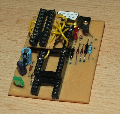
JDM PIC Programmer, with adaptor fitted.
Instructions of how to use the PIC programmer are available on the ICProg site.