
Hi-Fi LM3886 5.1 channel amplifier, with digital control - Power supply (PSU)
1 - Intro, 2 - The design, 3 - Pre-amplifier, 4 - Power Amplifiers, 5 - Power Supply, 6 - Grounding, 7 - Control - Hardware, 8 - Control - Software, 9 - Android App, 10 - Summary
Amplifier Power Supply
On this page...
The power supply is an important part of an amplifier and to ensure good performance and keep noise down, this PSU is perhaps a little over-engineered, but works very well and having looked around, you can engineer ones bigger and better than even this!
My amplifier build has many components and needs power supplies to provide the voltage and current I need in several areas:
- The LM3886 amplifiers - these have the highest power requirement and need a power supply outputting +/- 35V
- The preamp section - power for all op-amps and the PGA2310 needs a power supply capable of supplying +/-15V (+/- 12V is also ok)
- Microprocessor and digital sections - this needs a power supply of +5V
- Relays, soft-start and triggers - this needs a power supply of +12V
So that's four different power supply requirements. My goal for all power supplies was ultimately low-noise, but with efficiency too.
The ultimate efficiency is a switchmode power supply (SMPS) - these can reach efficiencies of more than 90% but operate at higher switching frequencies and that makes a DIY audio solution a challenge in particular, as layout and grounding results in scratching or whining noise on the amplifier output. I tried in the past to use LM2956 DC-DC converters (cheap modules admittedly) for the 5V and 12V PSUs, but I could not get them quiet enough. Therefore, what you will see here are linear PSUs for all outputs.
Linear PSUs are the quietest and easiest to work with, but they are not efficient. With some thoughts though, we can keep them fairly efficient.
The Power Amplifier PSU
This is the biggest power supply, and it occupies a third of the interior space in my amplifier case on its own! It outputs +/- 35V DC (give or take), that's a positive 35V, 0V and negative 35V.
Amplifiers are easiest to build and perform at their best when a power supply can give positive and negative voltages, because audio is AC, and an amplifier needs to send positive and negative voltages in either direction down the speaker cable in order to move that speaker cone out as well as in. If you do see a single supply amplifier, it needs a 1/2 voltage virtual ground, meaning a big capacitor on the output is needed to prevent that 1/2V DC reaching the speakers.
To get the best performance and reliability of this power supply, it is made up of several components:
- A toroidal transformer, which is 500VA and gives 2x25V AC outputs
- An unregulated CRC PSU with additional filtering and 6 large capacitors. This also forms the main system ground.
- To control the inrush current of that large transformer and all those capacitors, a soft-start circuit is used
- A mains DC blocker
- A mains loop breaker
The transformer
The mechanical part of the power supply is the 500VA toroidal transformer. This is one of the components that has remained in the build since its initial version, and I got it from Farnell in 2004. They last though, and their design/performance hasn't really evolved since, meaning a second-hand one will do you fine if found!
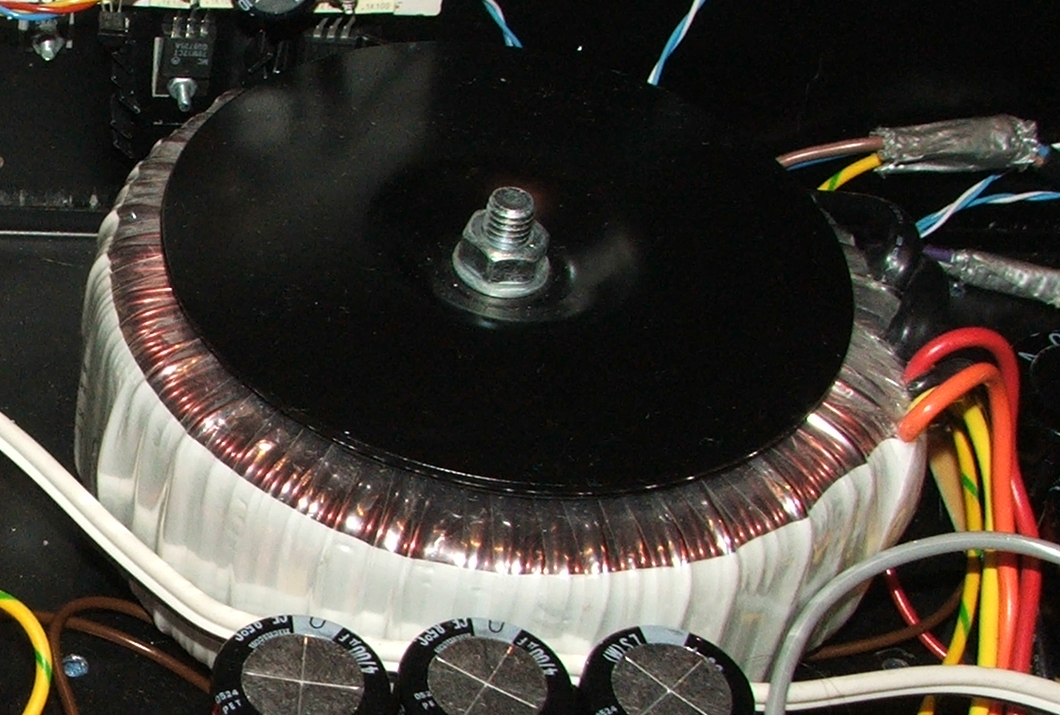
The transformer in its position, in my 2006 build
They do need to be sized appropriately though. For a stereo LM3886 amplifier, the recommended transformer is 160VA. Scale that up to 5 channels and that's 400VA. I use 500VA as I was originally bi-amplifying the front channels (meaning 7 amplifiers).
So 400VA will be fine for a 5 channel amplifier - but you may think even that's excessive? Well, the LM3886 is a class AB amplifier. Class AB amplifiers are common and easy to build, and many argue the best quality (apart from Class A, but those are really inefficient!), but they are not as efficient as their Class D and up successors.
A class AB amplifier will therefore lose power in the output stages, and a little before that too. That's why they need quite big heatsinks! Power is also lost in the power supply itself too, and taking losses into account, typical class AB efficiency is about 50%. So, with a 400VA power supply, you'll get max 40W output on all 5 channels (when feeding a sine wave at a constant frequency).
In the real world, on both music and films, typically the rear channels won't be working as hard, leaving a little more headroom. But even more in our favour is both music and films are very dynamic, and that high power is only needed at intervals. So yes - 400VA is enough, although my 500VA is better!
The LM3886 wants about +/-35V to drive 8-ohm speakers with significant power. That's DC though. When converting to DC, a bridge rectifier is recommended, but it has a multiplication factor √2 (about 1.414), minus some loss of about 2.4V (1.2V forward drop voltage per diode in the bridge). Therefore, an AC input of 25V is good, as it gives 35.35V when multiplied by 1.414. With the losses, it'll be about 33V.
Those figures are under load though. As this PSU is unregulated though, the unloaded voltage will be higher, and I get about +/-37V when idle. This won't harm the amplifiers but if you think that's headroom for the next transformer output voltage step up of 30V AC, it is not as voltages in excess of +/-45V will be harmful.
The PSU circuit, capacitors and rectifiers
The transformer gives us 25V AC - but connect that to an amplifier and it'll smoke! That AC needs to be converted to DC, and a smooth DC signal too.
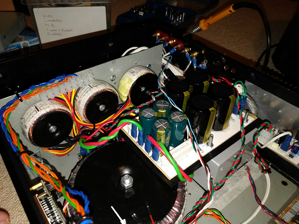
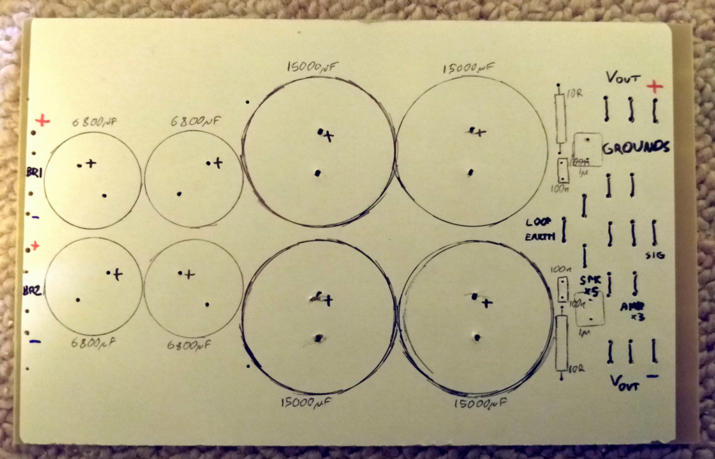
The PSU board, capacitors, resistors and connectors
I use bridge rectifiers to convert to DC. The best performance is given by the 35A bolt down ones. Bridge rectifiers can also be made up of four individual diodes. Some say to use high speed diodes for the best quality, but I'm unconvinced by the need because we only need to rectify the mains frequency in your country (so 50Hz, or 60Hz). But if used, they'll also work fine. I decided on 35A bridges, as I also need one for the DC blocker, and mains loop breaker so order a quantity of five (one spare) for a good price.
In parallel with the AC input to the rectifiers, I used 10 nF X-class capacitors as snubbers, in theory to reduce ringing. Not strictly necessary, but as I had them. You can also use one bridge rectifier instead, obtaining the zero-volt ground by connecting the two AC outputs of the transformer in series, to form a centre-tap. This is slightly more efficient (less diode losses) but risks more interference on the ground.
On its own, the rectifier will give a very chopped DC output. The rest of the PSU essentially filters that. Capacitors do the magic here!
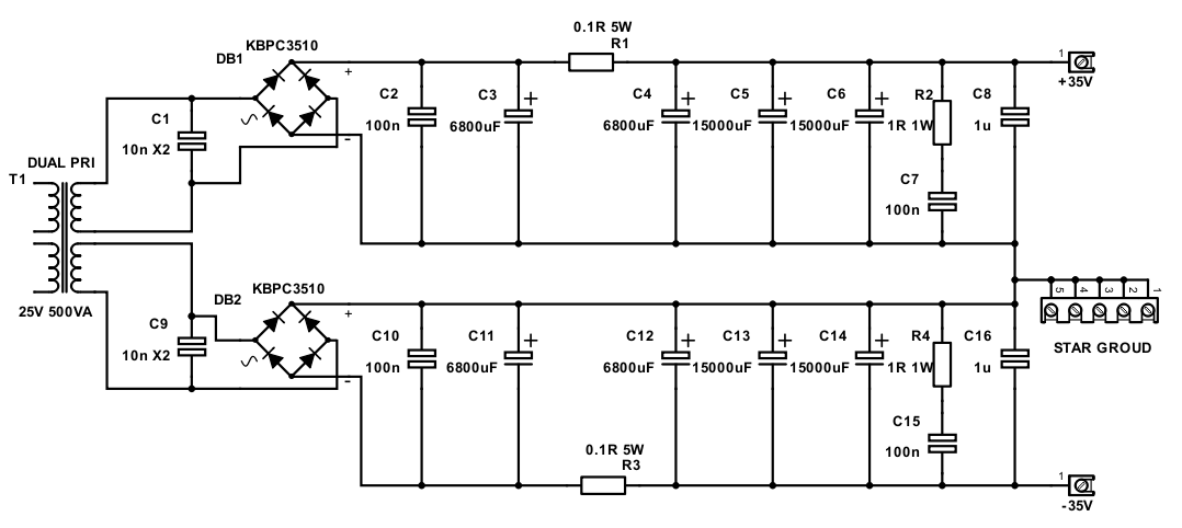
+/-35V PSU schematic
I went for a CRC design (well CRCC actually) for a little more regulation and also to form a low pass filter on the supply lines. Worried about efficiency (and heat!) driving five amplifiers at full power though, I kept the 'R' piece very small - using a 0.1 Ω resistor but quite a lot for the C part!
The capacitors do the smoothing. The higher the capacitance, the better the smoothing will be. Capacitors also need to handle the ripple current which would be drawn from the PSU at full power. Ratings of ripple current is sometimes hard to find, but it does correlate with size and bigger capacitors give better ripple current performance.
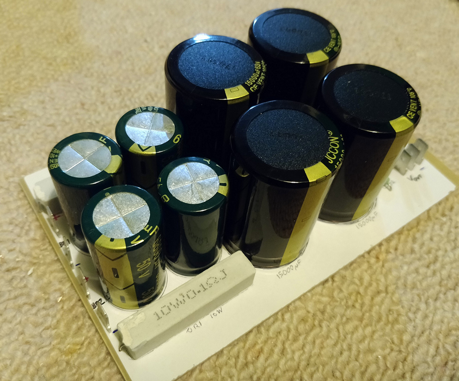
To meet my requirements, I used two 15,000 µF capacitors and one 6,800 µF capacitor per rail after the resistor. These are 63V/50V cans, and pretty large! The 'C' bit before the resistor is an additional 6,800 µF capacitor. So that's a total of 43,600 µF, per rail!
Yes, maybe I went a bit overboard - if you want to save money, less will still work and forget about the resistor, but given that 10,000 µF per rail is the recommendation for a good stereo amp, for five channels, double that at least. Capacitors age too, and their ability to hold charge reduces, so think long term too. Low ESR capacitors are recommended too (again larger is better as larger ones typically have lower ESR).
A secondary benefit of the capacitors in the PSU is that they also act as reservoirs, holding a charge which slowly drops over their time constant. This means that should the amplifier draw more power than the PSU can ordinarily deliver, it can still deliver it for a short moment, so long as a short moment after with less power draw follows to allow the capacitors to re-charge. Music is often like this, and it's why you can often see amplifiers work OK with technically under-rated PSUs.
Bypassing the capacitors are 1 µF polyester capacitors per rail, and a 100 nF snubber in series with a 10 Ω resistor.
Most of my PSU components, except for the bridge rectifier themselves, are PCB mounting, so I used a PCB for the PSU. This I prefer, but you can (and many do) build power supplies with point-to-point wiring. Capacitors with screw terminals can be obtained.
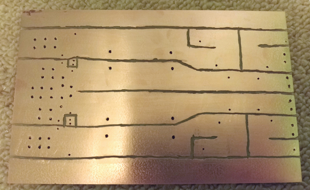
The bottom of the PCB, before soldering
The bottom of the PCB, before soldering
I went with a single sided PCB, but rather than etch the board like I do with nearly everything else, the simplicity of the board and its large size seems like a waste of etch resist pen and etching solution, so I instead used a mini power tool to cut away the copper, creating the layout this way. This leaves lots of copper on the board still, which is good to ensure power losses are minimised, and especially important for those ground currents.

The bottom of the PCB, after soldering. 100 nF ceramic capacitors (left) are mounted under the board
As you can see from the layout, it guides the flow through the first capacitor, then the resistor, then the other three capacitors, and bypass capacitor/snubber. The ground layout is split per bank but joined at the end. This is where my system ground is, and spade terminals are placed here for connecting grounds in the appropriate order (see next page).
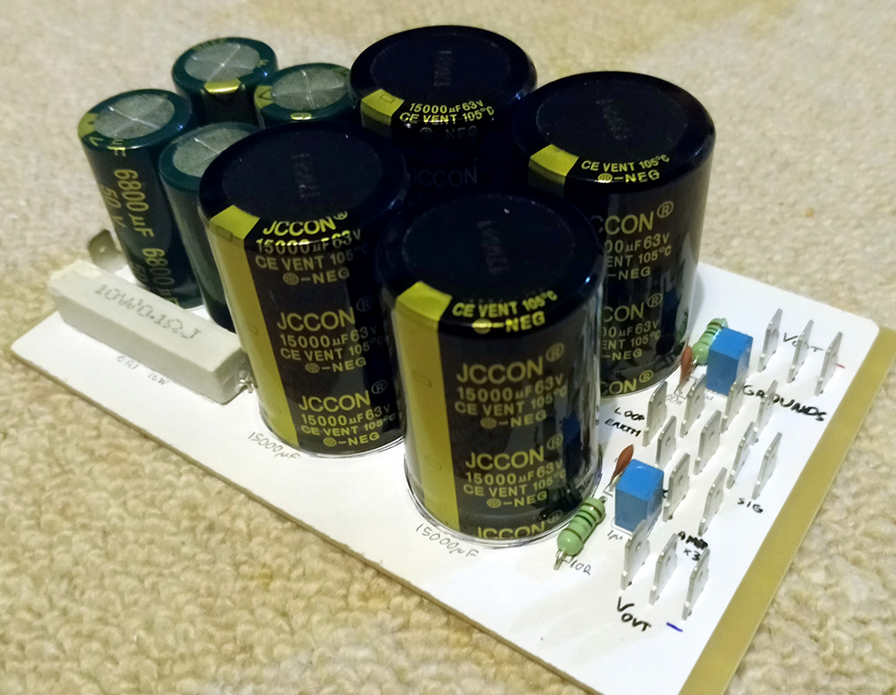
Completed board, showing the various output and many ground connectors
Optional are bleeder resistors. I didn't use them, as even with quite a lot of capacitance, it drains quick enough with idle amplifiers. During its initial test though I did leave the PSU completely unloaded, which gave about +/-38V unloaded voltage on the multimeter. 24 hours later, and it still had +/-30V despite not had any power fed to it - so if you don't like the sound of that - installing bleeder resistors will drain the capacitors far quicker, even unloaded. There's information about how to select the right value - because you need to think about power rating, how quick the PSU needs to discharge, minimising power loss during normal operation and voltage.
The Soft-start circuit
I remember when I was first testing my amplifier years ago with this 500VA transformer, the lights would actually dim for a brief moment when it was switched on!
This is inrush current, and it's normal for large toroidal transformers when first powered. Furthermore, those capacitors on the power supply will also be empty and will also drain current to charge up.
These inrush currents place the components under stress, and they will have a shorter lifespan than expected. A soft-start circuit solves this.
The simplest soft-start is an NTC thermistor, which has a resistance when cold and drops in resistance when it warms up (as that inrush current attempting to flow through it would do so). They do have some power loss though and more likely to fail earlier.
I went for a relay driven soft-start circuit. ESP project 39 is what I put together more than 14 years ago and it still operates reliably today. The only change I made to my original circuit was to remove its own 12V DC PSU and send a switched 12V signal direct from my PIC microcontroller board itself - allowing the PIC to power the amplifier on and off (my very early design had a mains switch on the front, and that was the only way to switch on/off).
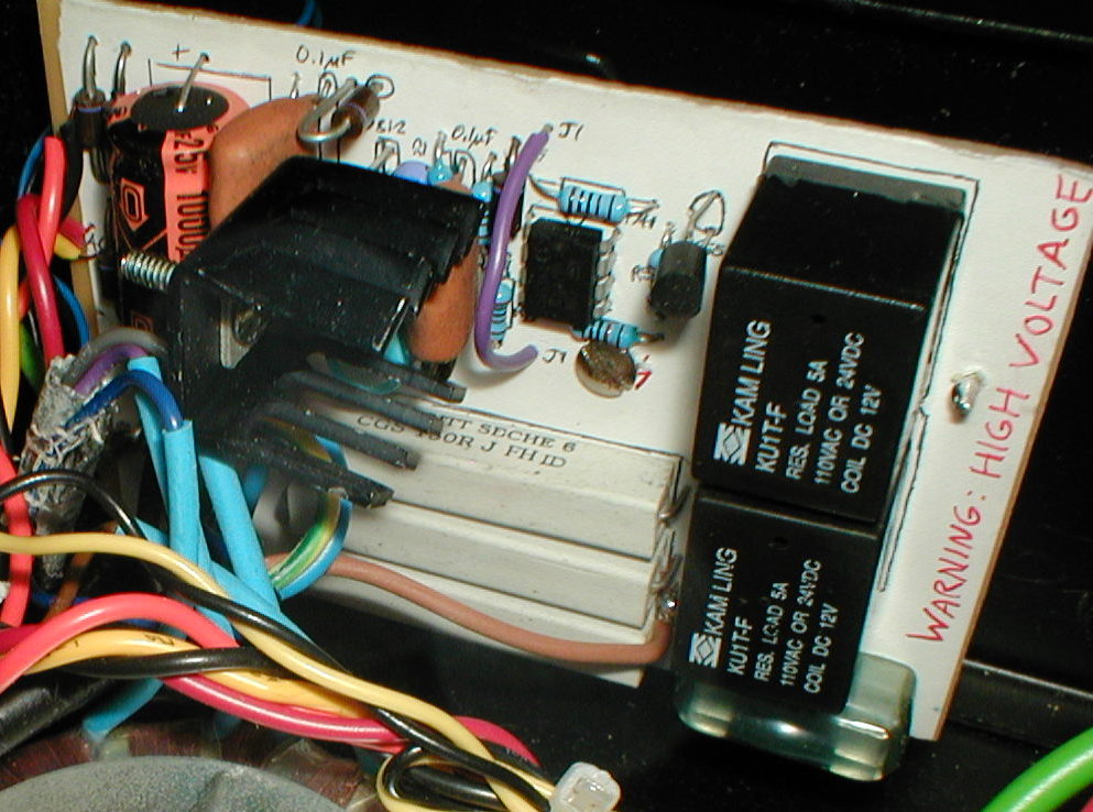
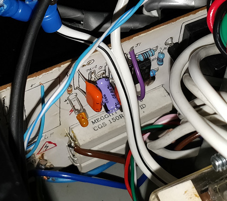
The soft start board - as it was in the original build, 2004
The soft start itself uses the 3x 150 Ω resistors in Rod's example. When the PIC sends 12V to the circuit, you can hear a click-click in close succession where the first relay activates immediately, sending the current via the resistors for a brief moment before the second relay activates, shorting those resistors. When the PIC drops that 12V signal down to 0V, both relays deactivate at the same time.
The soft start board - in place now in 2018
You could, as an alternative, have the microcontroller switch both relays and handle the delay at power on in software. This would work too, but an error in your code or wiring could result in the second relay not activating, leaving the resistors in the circuit for longer than they'll survive.
The DC blocker and loop breaker
I live in a block of flats in London (with a lift), surrounded by a train depot, sewage works, university and industries and retail. This does mean a varying amount of DC actually gets on the mains a fair bit, as well as brownouts. Big toroidal transformers (with low winding resistance) do not like DC on the mains and suffer from buzzing and I've had the amp completely on mute before and heard the transformer buzz fairly loudly and then quieten down again, with no change in load on the secondary windings.
Having read online about them (Rod also has a good article on it) and having two large capacitors and a spare bridge rectifier, I felt it would not cost me much to add this into my build. Some say (although I'd take that with salt) that not only has buzz and hum reduced, but bass on the amplifier improved too.
The 'cost' to me, was the purchase of a metal box that could envelope the capacitors, rectifier and mains wiring, and then the space consumed in the main amplifier by the box.
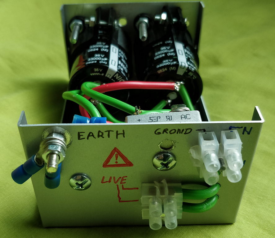
Connectors - screw for earth, terminal blocks for live in/out, 0V ground (goes to PSU star), and a neutral in/out (just for cable extension)
The box is earthed with a specific screw to the mains safety earth (yellow/green wire) but insulated from the rest of the case to prevent earth loops on main case. It safely contains the capacitors (which are at mains AC through them), the rectifier diodes (which takes most of the mains AC through it) and wiring. Should any of these fail, the safety earth will prevent additional damage, and even if the capacitors do fail early, they aren't going to make a mess of the rest of the case by sending oil and fluff everywhere!
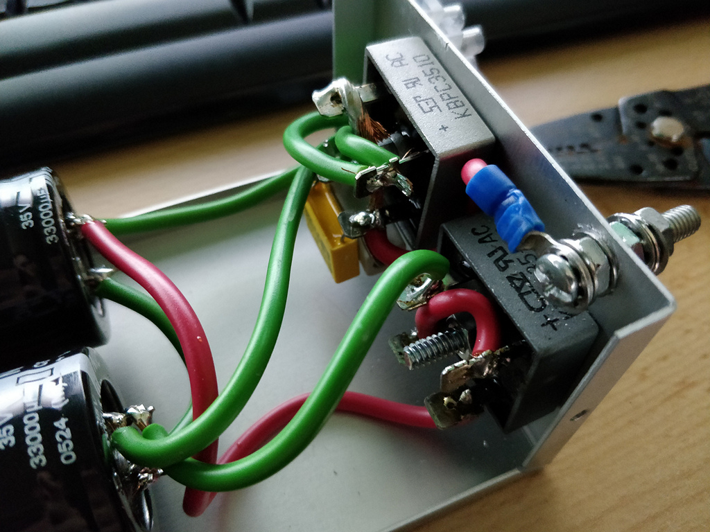
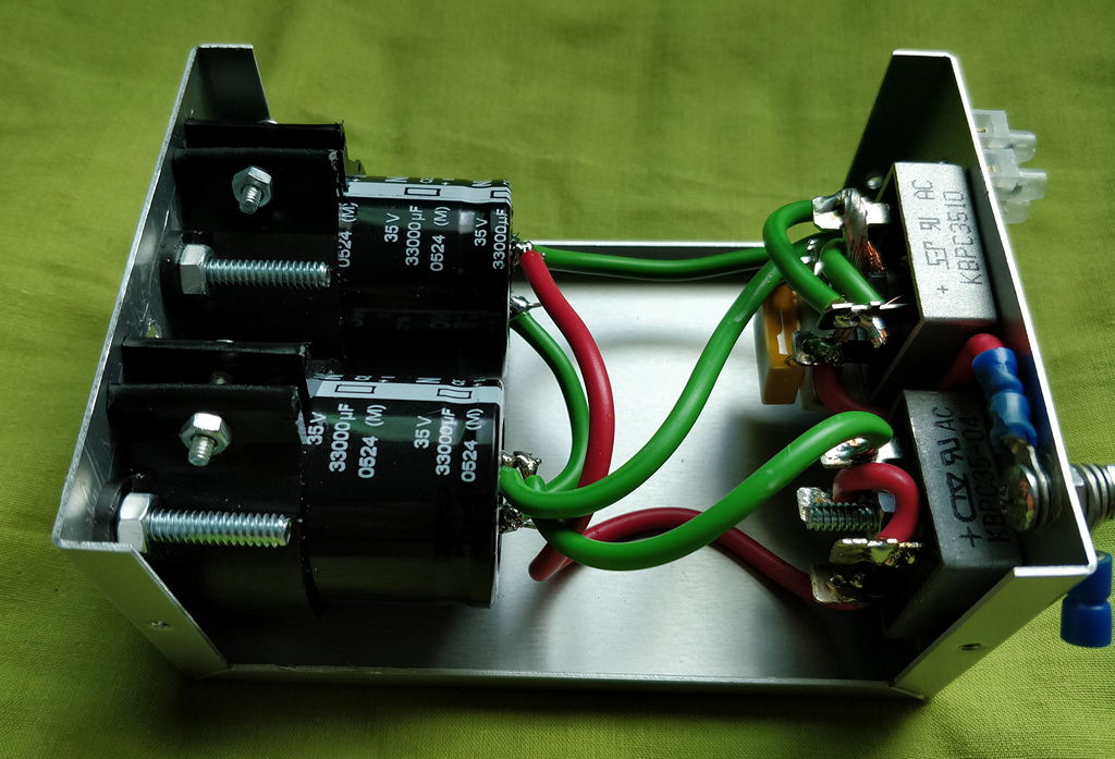
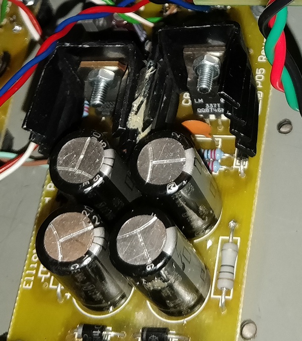
Top - loop breaker using a 35A rectifier, bottom, DC blocker using a 35A rectifier
Inside this box, I've also placed the ground loop breaker here. Again, Rod has a good article on them, but what this is essentially doing is breaking a low voltage, low current connection between the safety earth, and the main system ground (where the audio ground is also connected). This prevents a hum loop from forming around the audio cables and the safety earth to the plug socket when using another piece of equipment where the audio ground is directly connected to the safety earth.
Should a fault occur (i.e., mains cable falling free and touching a circuit board, or transformer shorting the primary and second coils together) - the diodes in the loop breaker will conduct this faulty voltage to safety earth, tripping the circuit breaker in the home and protecting me or my wife from maybe being killed by touching an interconnect or similar. The metal case is directly connected to safety earth. See the next page (grounding) for details on the loop breaker.
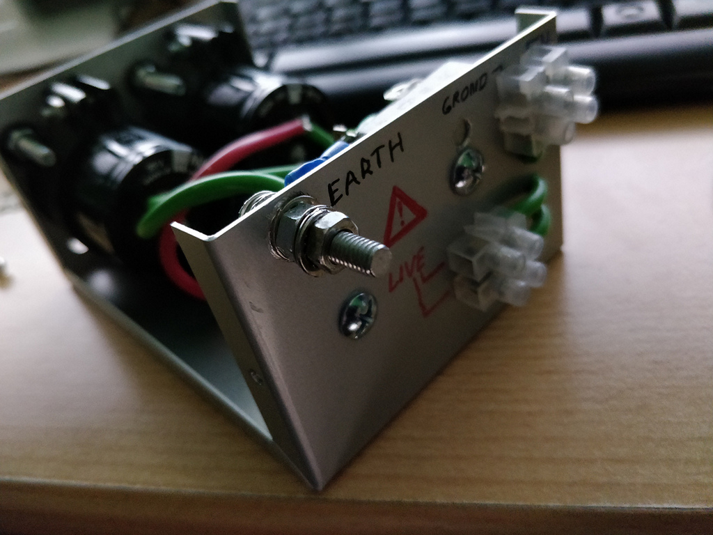
The earth connector needs to be reliable - tooth washers, locking nuts used throughout to ensure good connection to the metal of the box
The capacitors need to be big because they are handling a large ripple current, low ESR, and also enclosed so can warm up. Larger capacitors deal with this easier and I had some spare 33,000 µF 35V capacitors which do the job nicely. Two capacitors are used in series, so there is no worry about the reverse voltage shortening the life of the capacitors, but it does halve the total ripple and capacitance, so really my setup is 16,500 µF. If you know the ripple current of your capacitors and verify the total ripple on the peak demand for the system, you can use less (would still recommend 10,000 µF though). My capacitors are an old purchase though and I can't find data for them, hence I went with the biggest I could!
If you can - get capacitors with screw down terminals, and crimp spade connectors for the rectifier. This is safer than using solder on mains connections, and if you do use solder like I have, absolutely make sure the setup is protected in its own case.
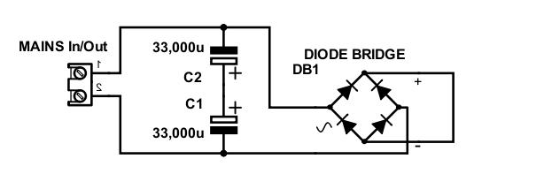
Mains DC Blocker schematic
In my system, the DC blocker is used on the live mains in series (would also work on neutral, there are pros/cons to choosing either!) with the main 500VA transformer only. The other three 15VA transformers are connected directly as they are so small that the wiring resistance inside them blocks DC anyway.
The DC blocker works fine and didn't cost me much so happy I included it in my system. It isn't essential though and if you're looking to save cost, you can here. Equally, if you're using a smaller transformer, say for a stereo amplifier (300VA or less), or mono-blocks, it is not required.
Pre-Amplifier Power Supply
Apart from being inside the same case - I really treated the pre-amplifier as a separate system, with its own PSU and ground layout. This improves performance and I feel reduces the risk of getting grounding wrong, as well as improving efficiency (where linear regulators are involved).
The pre-amplifier runs off +/-15V (although +/-12V would also be fine). A 15V AC transformer when rectified gives about 20-22V DC, which is ideal for input into 15V linear regulators.
I only have 13 op-amps in total (some with no gain), and three PGA2310 chips. Current draw on +/-15V is not very much, but I wanted to keep with toroidal transformers all-round and 15VA is the size they start at. This is ideal for a pre-amp.
To rectifier and regulate the 15V AC into a smooth +15V and -15V DC voltages, I use ESP project 5 (rev b). This uses LM317 and LM337 linear regulators and I brought the PCB to get the specific component values, well designed layout and convenience of putting it together. The AUX output I don't use, as muting is done by my PIC controller and a dedicated 12V PSU.
Control Power Supply
Update: I revised the control power supply to use a single transformer for the two outputs.
The remaining power lines I need is 5V for the PIC microcontroller and it's peripherals, and as 12V PSU for relays and triggers. These are single rail PSUs, giving a positive output only (no negative), and 0V.
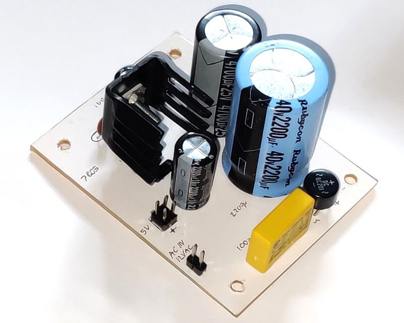
A single 9V AC transformer at 15VA will give around 12V unregulated DC, which is fine for powering relays. This unregulated DC can also feed a 7805 regulator for the 5V output.
An issue is the 5V regulated output is put through a linear regulator - the old reliable LM7805. With an approximate 12V DC input though, efficiency is only 41%, as the 7V extra voltage is thrown away as heat when current is drawn on the output.
On standby - the power and pre-amp PSUs are completely off, but the 5V and 12V ones are not. They run 24x7. As of July 2022, I've removed Bluetooth support so that I can have a low current draw. I measured 24mA to 70mA at current draw at the 5V output on standby (my multimeter is not very accurate). This is at most 0.4W at the output, and 0.9W at the input (meaning about 0.5W heat is generated). At the wall, I measured 1 to 1.2W power, which is as expected as they'll be losses in the transformer and bridge rectifier too prior to the regulator.
I did try an alternative switching PSU using an RS Pro K7805M-1000M replacement regulator, with chokes/beads before and after. I had success with this in my STA540 amplifier, however, here it added audible noise on the output of all amplifiers. I suspect the far more complicated layout here and grounding causes the issues and I do not have enough time to thoroughly diagnose it.
I did measure a reduced at-wall power draw of 0.7W to 1W on standby. There's still some loss in the transformer and bridge rectifier that cause this and only a mains input SMPS would reduce that further, but there are not many dual output ones, and they could perform worse than the K7805M.
Powered on, the current draw increases to a range of 150mA to 200mA. The MAX7219 displays will explain most of that, but also the current draw on the PIC and 74HCT595/ULN2003A pins from the relay load. I didn't measure 12V current draw, but in total at the wall without amplifiers the power drawn is 5.2W to 5.8W. I reduced this slightly to 5.6W by reducing the MAX7219 duty cycle (brightness) later.
Under load (and even a bit on standby), the 7805 regulator does generate a fair bit of heat and needs a small heatsink. I mounted an independent heatsink for simplicity. You could mount to the case too, but remember their tab is electrically connected to ground. Therefore, to avoid shorting the digital ground / 0V to the case rather than via the loop breaker, insulating washers need to be fitted.
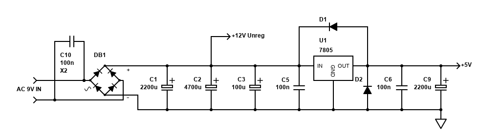
12V unregulated and 5V regulated PSU schematic
The 12V output is unregulated. 12V coil relays will typically work from 9V to 14V. Unloaded, the 12V output measures 12V anyway as there is always some power drawn by the 7805 regulator. With relays active, it drops to 11V, and this is still fine. All relays reliably activate.
That concludes details about my power supplies. Read on to see how it comes together with grounding!
References and more reading:
ESP - Linear Power Supply Design
ESP - How to Wire a Power Supply
ESP - Blocking Mains DC Offset
ESP - Earthing Your Hi-Fi - Tricks and Techniques
Mark Hennessy - Power Supply Basics
Texas Instruments AN-1849 An Audio Amplifier Power Supply Design
PALADIN - CRC Filter Supply
diyaudiocart - High Quality Dual Rail
Universal CRC PSU PCB
Decibel Dungeon - Building a Gainclone (chip amp) with a snubberized PSU
Circuit Basics - How to Design and Build an Amplifier With the
TDA2050/
diyAudio - Tuning a PS Transformer on a
GainClone
TNT Audio - Solid State Power Amplifier Supply
REUK.co.uk - LM317 Voltage Calculator
Learning about Electronics - Low Pass Filter
Calculator
Further pages here...