
Hi-Fi LM3886 5.1 channel amplifier, with digital control - Preamplifier
1 - Intro, 2 - The design, 3 - Pre-amplifier, 4 - Power Amplifiers, 5 - Power Supply, 6 - Grounding, 7 - Control - Hardware, 8 - Control - Software, 9 - Android App, 10 - Summary
Preamplifier
On this page...
The preamplifier is based around several components:
- The PGA2310 preamplifier, x3 to cover the 6 channels individually, with input and output operational amplifiers as per Mark Hennessy's design
- A simple 'Hafler' style surround sound processor, Rod Elliott's ESP Project 18
- A digital delay using PT2399 to improve the rear speaker effect, Rod Elliott's ESP Project 26 and 26A
- A phono preamplifier for the turntable, Rod Elliott's ESP Project 6
- A rumble filter for the turntable, Rod Elliott's ESP Project 99
- A low noise power supply, Rod Elliott's ESP Project 5A
- PIC18F4455 control (more on this later)
The preamplifier hasn't really evolved much since the first time I built it years ago, as a separate module. The design consists of the input signal going to a series of relays, used to select the active input I want. The stereo signal is fed to the main front left/left preamp, and also the internal surround sound decoder. A series of relays also control whether I want the surround sound signal to be taken from the internal decoder, or an external decoder (given the 5.1 capability).
Main preamp board
The preamp board itself consists of three identical PGA2310 controlled preamps, each having an OPA2134 input buffer, and another OPA2134 output, lifting overall gain to about +1dB. Additionally, the main board contains the surround sound decoder, and delay unit with cut/gain buffers.
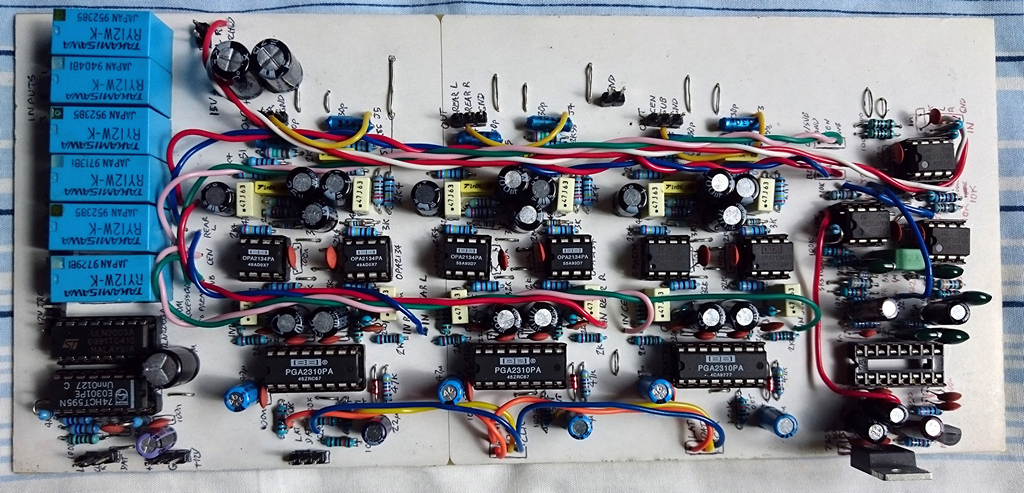
Preamp board, top with all components (except PT2399)
The circuit board itself is my 'Revision C' attempt. Revision A was my original preamp - which had separate boards for front, surround, and processor (although it did support 7.1). Revision B combined them into a single board which went into my first attempt of combining the preamplifier and power amplifier projects together but had the rear delay circuit off-board.
Revision C I felt necessary to build in order to reduce the number of PCBs by having all 6 channels, the surround sound processor, digital delay and buffers, accommodate different sized relays for switching line level signals (Takamisawa RY12W-K), and revising the ground layout of the PCB traces. My revision B also had some mistakes so correcting these was good too.
The board however is very complex. The amount of time it took to pencil out the layout was significant, and the board itself was a multi-day job. The sheer number of holes to drill to hold 6x 14-16 pin ICs, 9x 8 pin ICs, 6 DPDT relays and a large amount of capacitors, resistors and connectors took hours to drill! I am however very pleased with the result - all components fit in place, and it performs well.
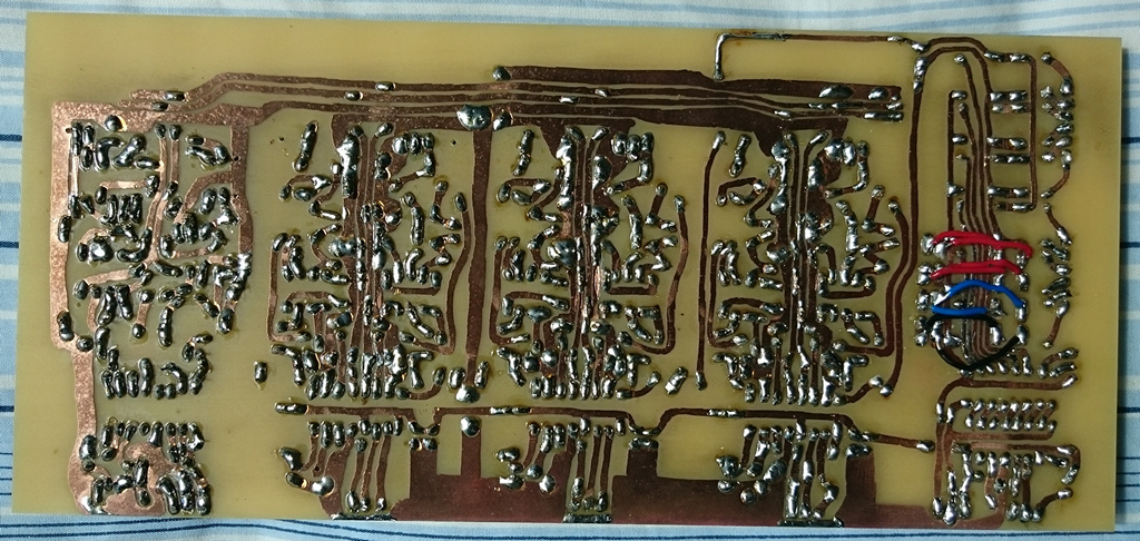
Preamp board - soldered underside
I stuck to PCB layout guidelines on this attempt more than I used to. The important one is grounding. Whilst a ground plane could also work well - I stuck with ground PCB traces - keeping them wide and connecting them all only at a single point, after filtering the power supply.
Ground and power traces are also filtered at every IC - with 100 nF capacitors as close as possible, and 100 μF capacitors next nearest. Ground is also split into two halves - digital on the bottom edge of the board, and analogue in the middle and top edge. In the very centre, the two grounds are connected to each other on this board itself and never connected again externally.
Connectors are located near the edges of the board to allow easy access, and they are all Dupont connectors. Power, audio and digital interface connectors are separate. Since a layout was attempted with a single sided PCB, it does need some jump wires to prevent a crazy layout. Wires I used I kept short and directly soldered them into the board at both ends.
Relays - on my previous Revision board, after a few years, I had some unreliability with the sound and occasionally one channel would stop working. For a while until my rebuild was complete - I would give the amplifier a quick physical hit with the hand to resolve it! This I traced to the relays, after painfully checking many wires and components. The relays I used were power relays and their long-term reliability actually depends on some arcing when switching power currents to keep the contacts clean, otherwise the silver on the contacts tarnishes. You don't get that kind of arcing with the tiny current on AC audio line-level signals.
The solution can be solved by getting the appropriate relays and recommendations seem to go out to the Takamisawa RY12W-K - a relay with high reliability gold plated contacts. I brought a dozen and used them in the new design. In operation they use less power when switching on than my old relays did, and the click is quieter. As an extra benefit, they also take less room on the board too.
Switching the relays is done using a Shift Register connected directly to a Darlington Transistor array. The Shift Register chip is the 74HCT595 and it allows me to control an 8-pin output with a 3-wire serial input. The ULN2003A Darlington Transistor array is so that the 5V parallel output from the shift register can be used to switch 12V relays. This has 7 transistors in it, so one of the eight parallel outputs of the 74HCT595 is just left unused.
The 7 controllable outputs are then used for my relays:
- 5.1 input stereo front channel selection
- Second stereo input (i.e., Television)
- Third stereo input (i.e., from phone pre-amplifier)
- Fourth stereo input (i.e., an auxiliary)
- External / Internal surround decoding (this output connects to two relays, effectively making a 4PDT switch)
- An optional 12V trigger
- A second optional 12V trigger
The PGA2310 chips are installed as per Mark Hennessy's design, but with my own PCB layout, and simplified to remove A+B sum, headphone amplifier and other features. I encourage you to read more about the design at his Hi-Fi Preamp pages.
The surround sound processor is from Rod Elliott's design - ESP project 18. This is really simple, using one dual op-amp to get me both the rear channels, and the centre and sub channels.
For the rear channel, the rear output of Project 18, is then sent to a PT2399 digital delay circuit. Essentially this is Project 26A, but as I was worried about the possibility of distortion on big input signals, I used the Input Buffer and Output Driver from the original Project 26. For one more trick, I used an additional opamp to invert the output for one of the rear channels only - giving the out-of-phase requirement effect as mentioned in Rod's notes without having to connect one of the rear speaker leads reversed.
Additional boards
The additional functionality was provided by three ESP projects I purchased the boards for to show my appreciation and ensure the circuits were good quality.
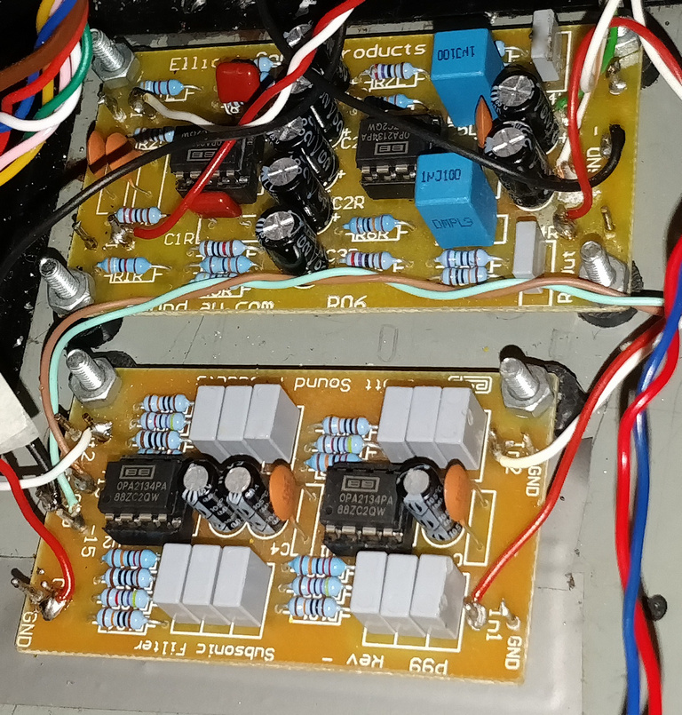
P06 and P99 boards in place (during rebuild)
- The phono preamplifier for the turntable, ESP Project 6
- A rumble filter for the turntable, ESP Project 99
- A low noise power supply, ESP Project 5C (mine was 5A but get the latest!)
Not much more to say here other than I recommend them! The phono amplifier is very good.
That concludes details about my pre-amplifier. It is important to read the Control page though to understand how the preamplifier is controlled (volume and input selection).
References and more reading:
Mark Hennessy - Hi-Fi Preamp
ESP Project 18 - Simple Surround Sound Decoder
ESP Project 26A - Digital Delay Unit For Surround Sound, Reverb, Echo & PA
ESP Project 26 - Digital Delay Unit For Surround Sound
ESP Project 06 - Hi-Fi Phono Preamp (RIAA Equalisation)
ESP Project 99 - Subsonic Filter for Phono preamps, Sub-Woofers, PA Systems, Etc
PGA2310 Datasheet
OPA2134 Datasheet
ULN2003A Datasheet
74HCT595 Datasheet
PT2399 Datasheet
Further pages here...