
PIC Microchip Guide, Tools and Tips
My first adventures with the PIC microchip were at university in around 2004 as part of the computer science degree... learning how to program it in assembler to drive a stepper motor.
I struggled at the time, as I'd just been taught to program only a year before and assembler is a bit scary at first and even now, I doubt I could punch out a working system with assembler anywhere near as fast as I could in a high level language like C.
Despite the initial struggle, my enjoyment of DIY audio electronics was to feature in my final year project, where I built a pre-amplifier and used the PIC microcontroller to control it. I actually succeeded, but I wrote it in C instead of assembler.
Now I've built a fair few projects with the PIC micro since and whilst there are plenty of information available online these days, I want to share what works for me and hopefully inspire at least someone to pick up these cheap chips and build a project from them.
These days, there are alternatives. Arduino is very popular now but was unheard of in 2005. Even Raspberry Pi foundation have released the Raspberry Pi Pico. There are ESP-01 modules or ESP32 too. All these are good alternatives for the beginner, but you buy the board and add I/O around it. My preference has always been to build the board, with the design I want, and buy the right chip for my needs.
PIC microcontrollers are cheap. Some are less than £1! Most are less than £4. A few other components will be needed to support them in a circuit, but this will only be a few capacitors, resistors and diodes and you'll get those included in most component starter kits.
What we need in addition to the chip though is hardware and software to program it.
Hardware Programmer
A programmer is required to burn the compiled hex file on to the chip.
I can't remember what I used in my university lab originally, but when I built my own project, I started with a JDM programmer. This is a simple programmer that's easy to build but requires a PC with a built in RS232 serial port. These were still fairly common in 2005, but started disappearing not long after.
You could still go down this route to build a simple cheap programmer if you have a PC with a serial port (some PC motherboards DO have internal headers for serial connecting ports still, but you'll need to buy a cable). Note that USB to RS232 adaptors do exist, but they don't necessarily have the capability to drive the RS232 to the voltage levels needed to program a PIC.
Many programmers can be purchased now, quite cheaply. That was not the case in 2005 but now you can search for them easily on auction sites. I've never used them though and cannot make any recommendations. For myself, once I realised the parallel port was being dropped from PCs, I built a USB programmer myself following the open source design at UsbPicProg, around 2009 or 2010, I think. Sadly, now though, the project looks a little dead (but not completely), with very little updates since 2015 - a shame because it's actually very good and clearly a lot of effort went in to it!
There is a through hole design that allowed me to use components I mostly already had, and I managed to copy the design by drawing it on to double sided copper board and etching. The PIC18F2550 was purchased and programmed using the old JDM programmer once, with an ICSP lead solder-bodged on to the back of it.
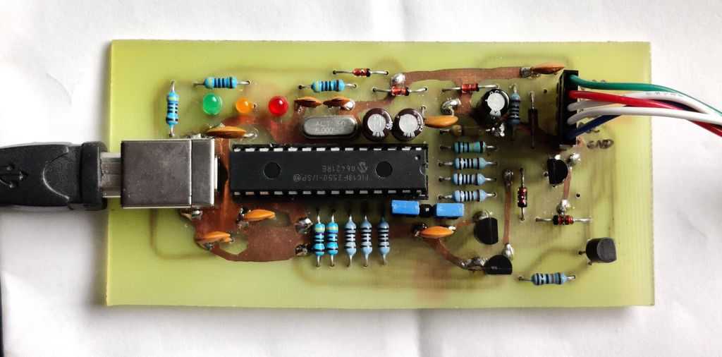
My copy works well, and I still use it today. I have a ZIF adaptor for some PIC microcontrollers, but in all my recent board designs I've always incorporated an ICSP (in-circuit serial programming) header which allows me to connect the programmer directly to my circuit without having to pull the chip out of its original socket, insert into another socket for programming and then transfer it back after (each time risking pin bending or incorrect orientation).
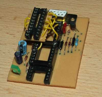
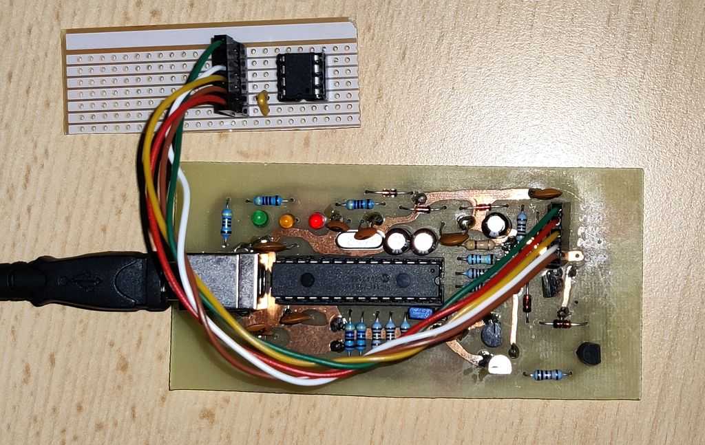
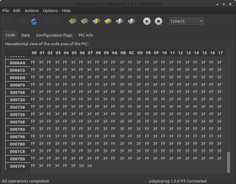
UsbPicProg is designed to program PICs via an ICSP header, but it is easy to create simple boards for programming a PIC out of circuit, such as a simple Stripboard/Veroboard adaptor for the PIC12F675, pictured below.
The UsbPicProg PC software is well written and works well. It still works with Windows 10, just follow the same instructions as the Windows 8 driver.
I do now use the Ubuntu version of UsbPicProg. The latest version 1.0.8 works on Linux Mint 21 (which means it's fine in Ubuntu 22.04 and similar), just choose 'No' when asked to update the firmware on the programmer and it works fine! The PPA hasn't been updated for Jammy Jellyfish, but grabbing the deb works.
Software - IDE and Compiler
To write code and compiling down to a hex file for burning on to the PIC, we need some software on our PC.
I came across SourceBoost in 2005 when looking for a C compiler for PIC microcontrollers. It was the cheapest at the time, and still looked good. At the time the compiler was C2C, and I later upgraded the licence to BoostC. The SourceBoost IDE and the compiler are now donation-ware. This means you can download it and get going straight away without a committment. If you like it - then donate! I've not migrated to their new Chameleon compiler as BoostC is included and works very well for me and supports many PIC microcontrollers.
SourceBoost is Windows only, but it's worked in every version I've had of Windows since XP, including Windows 10, and also was very easy to install and get up and running on Linux using PlayOnLinux (wine). Again, it's another big piece of work with very little updates in the last decade, but it's still there and works well! Alternative C compilers for PIC are still too expensive for hobbyists. They also have a BoostBasic compiler, though I've not tried it.
You may find alternative compilers, Great Cow BASIC might be a good FOS (free open source) one. BASIC is a good language for beginners and shouldn't necessarily be ignored by professionals either.
About the microchips
There are many PIC chips. Some of the popular ones I'll recommend are obsolete, but still easy to get and cheap.
For the DIY hobbyist, the through hole DIP chips are likely best. Many surface mount PICs also exist, but you'll need to solder them on adaptors to fit them in breadboard or stripboard / Veroboard. Even if you make your own PCB, unless a small size really matters, I'd recommend standard through hole DIP.
The cheapest and smallest DIP PIC is the PIC12F675. This is an 8-pin microcontroller, which has a maximum of 6 I/O ports. Specification is very low, 1024 (1k) words of flash program memory, 64 bytes of RAM, 20Mhz clock input speed (which will translate to an instruction every 200 nanoseconds). It has an EEPROM too (128 bytes), allowing you to save runtime data so settings can be 'remembered' after removing the power.
For some projects, like simple timers or a simple thermometer, this PIC may be all that's required.
If you need more I/O, or more code space, the PIC16F627A or PIC16F628A are popular and cheap too. These are 18 pin chips with more 16 possible I/O pins. Again, specification is low - 1024 or 2048 words. RAM is a bit higher - 224 bytes. They also have EEPROM (128 bytes).
Larger PICs can come in 28 or 40 pin DIP/PDIP formats, which have a large I/O capability. I've used, PIC16F873 and PIC16F877 in my projects, or for more capability you can move on to the PIC18 chips, such as the PIC18F2455 or PIC18F4455 - these have 12k words (24k bytes) of flash memory, 2048 bytes of RAM and clock source support of up to 48Mhz (instruction every 83.33ns).
Picking the right one for your project is actually crucial and designing the circuit around it after is just as crucial. You will need to know:
- Your direct inputs - switches, keypads, analogue sensors, IR receivers etc.,
- Digital inputs via sensors, such as thermometers, PIR sensors - they will all use a protocol such as SPI, I2C/TWI, 1-wire, ...
- Your direct outputs - LEDs, relays, motors, speakers/buzzers ...
- Outputs that contain their own chips - LCD displays, LED 7-segment/matrix drivers, audio processors, shift registers
- RS232 or USB support to interface with a PC or Bluetooth
You'll also need to have some idea about how complex your project code is going to be. If writing it in C, which is easier, it will use more instructions in that limited flash ROM then a well-written assembler program. I sometimes start with a target in mind and write some code before I actually buy the PIC and build the circuit.
Design tips
With that, here are some tips and notes that I've put together that you should review with your design. Click these to jump down and read further:
- PIC types and reuse - beware of PIC12C, PIC16C and PIC18C 'C' variants and code protection
- Oscillators and Speed - consider the internal oscillator and calibration if the PIC has one, or an external crystal
- Input only pins, MCLR port - MCLR can be set as I/O but as input only and ICSP (programming in circuit) can be a challenge if used
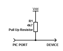
- Open-drain output pins - beware of the open drain pin, you may need a pull up resistor if used as an output
- Comparator and ADC pins - if you want to use these pins as normal digital I/O, you'll need to disable comparator and/or ADC first
- Schmitt Triggers - only some pins have ST inputs, so design wisely
- ICSP In-Circuit Serial Programming Pins - keep these pins dedicated for in-circuit pin if you can, and use this schematic to avoid interference with the rest of the circuit
- Interrupts - make use of them!
- External Interrupt(s) - a great way to reach quickly to a change of state, or wake the PIC up from sleep
- On-Change Interrupt - another way to allow more inputs to generate an interrupt on state change
- Comparator Interrupt - and another way to generate an interrupt from pin state change
- Communications - USART / Serial Communications Interface (RS232) - classic serial communication, often built into PIC hardware
- Synchronous Serial Port (SSP) / Master Synchronous Serial Port (MSSP) - hardware SPI or I2C support. You can't have both, and using them may block other features too, however, use them if you can
- I2C - here are some MSSP/SSP hardware I2C samples in Boost C
- EEPROM - save your data if you need it after complete power removal
- PWM - Hardware Pulse Width Modulation - control of analogue speed, brightness etc. Check what pins are supported.
PIC types and reuse - beware of PIC12C, PIC16C and PIC18C 'C' variants and code protection
Most PICs should be 'F' variants, such as PIC16Fxxx, but you may come across 'C' variants. These are 'flash once' chips which can be programmed only once and never again. Some old ones can be erased and programmed again with a UV light, but honestly, it's not worth the effort.
You will have bugs on your first go, so get a PIC that can be flashed many times.
Any PIC you recover from consumer or professional hardware is unlikely to be repurposed too (even if it is an 'F' chip), due to code protection (read and write).
Oscillators and Speed
4Mhz is a common speed. For all the PICs I know, one instruction cycle consists of four oscillator periods. This translates to one instruction every microsecond. Depending on how you look at it - that's very fast, or pretty damn slow! For reading buttons, multiplexing displays or turning LEDs or motors on or off, it's plenty fast enough.
You can start to hit speed limits when interfacing with other protocols though, such as reading infrared commands from a remote and processing them in a timely fashion. The RC5 IR code featured on my site is capable of running at 4Mhz thanks to running off timers and pin change interrupts, but I struggled with other alternatives. If you need to send serial data with lots of bytes too, this can be a challenge and I hit speed limits in my DAB amplifier as I could not process the data sent from the radio and send it to my own OLED display before the next data was sent, leading me to implement a circular buffer and interrupt driven I2C receiving.
All PICs are single threaded processors - there is no multi-tasking, unless you code it. Even then it will pause on task, process another etc. If you expect to be processing data frequently, or polling for time critical (nanosecond/microsecond) input, then consider adding a second microchip and make them communicate with each other via a bus.
If you can though, using 4Mhz is convenient as many PICs have an internal oscillator configured to run at this speed (some are 8Mhz, some are even selectable). Lower speeds also lead to less power usage, crucial for anything battery operated, but also handy to reduce power consumption for anything mains powered when your using linear regulators.
Some PICs though (like the PIC16F7X - PIC16F73 to PIC16F77) do not have internal oscillators. For these, you must connect an external quartz crystal or capacitor resonator. Passive quartz crystals of 4Mhz or 8Mhz are cheap and easy to find. They must be loaded with some small ceramic capacitors too (10 to 33pF - see relevant datasheet). Note that the crystals are often called 'Crystal Oscillators', but technically it's just a passive crystal resonator - the 'oscillator' is formed with the capacitors and the components in the PIC.
If you do use the internal oscillator, these are factory configured, but you need to read the word in your program for good timing performance, below is an example for the PIC12F675 that can be embedded into a BoostC program:
    // Use oscillator calibration value by copying it to OSCCAL
    asm {
        call 0x3FF
        bsf _status, RP0
        movwf _osccal
        bcf _status, RP0
    }
So, in summary, my advice is:
- Check if your PIC has an internal oscillator and what speed - use that if you can but read the calibration word and apply to OSCCAL in your program.
- Use a crystal resonator otherwise, but check what the loading capacitors should be
- Higher speed helps, but increases power draw
- If you use an external crystal, you could be losing 2 pins of I/O - review the remaining I/O pins covers everything you need
Input only pins, MCLR port
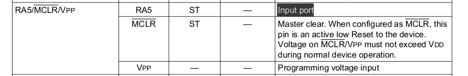
Most I/O pins on a PIC are bidirectional, but some I/O pins are input only. This is often the MCLR pin, which can sometimes be re-purposed as an I/O pin.
If you want to use the MCLR port as an input, you have to set the CONFIG variable appropriately. This varies per PIC. As an example, for the PIC16F62XA, it's bit 5 of the CONFIG register (which is set during programming):

Note that if you use the MCLR pin for input, you might not be able to use ICSP, so my recommendation is to plan not to use it at all.
Open-drain output pins

Most I/O output pins are CMOS but check for open drain (OD) pins. On some PICs, this is often RA4. If you are using it as an output, you have to use an external pull up resistor in order to get a logic high output. This has caught me out before and I've had to bodge a resistor to the nearest VDD (i.e., +5V) from that pin in order to send logic high.
Comparator and ADC pins
![]()
Some PICs come with an analogue comparator, others with an ADC. If you are using a pin for standard digital I/O and not the comparator, be aware that the default for CMCON, which controls the comparators is 0000 0000 which actually means on.
In your code, you must set CMCON to 7 (0x07 or 0000 0111) in code during initialisation.
For PICs with an ADC, you need to set the ADCON1 register (in code). Refer to the datasheet, but usually setting ADCON1 to 7 to disable ADC for all pins. Example for PIC16F87X / PIC16F7X.
![]()
For PIC12F, ANSEL should also be set to 0 as the reset value default is 0000 1111, as well as setting the CMCON to 7
Schmitt Triggers
For inputs that are not true TTL, PIC micros usually have Schmitt Trigger pins.
These types of input pins reduce noise and can also be used to get a true/false value from an analogue input (such as converting a sine wave to a true/false square wave digital input).

These can be handy at triggering external inputs, such as from a switch, AC signal, timing crystals and many others. Schmitt Trigger inputs are not necessary for pure digital inputs, such as an external chip sending data to your PIC.
If you need a Schmitt Trigger input, but do not have enough Schmitt Trigger input pins (but have spare TTL inputs), then you can consider using a 74HC14 / 74HCT14 (Hex Inverting Schmitt Trigger) can be used to buffer the input - this has six triggers, so if you want the original signal to not be inverted, you can chain two of them.
ICSP In-Circuit Serial Programming Pins
One way to program the PIC is to physically lift it out of the operating circuit and place it into a programmer. This assumes that PIC is in a socket in the operating circuit and can be removed.
This gets annoying though, and the chip or socket can wear out when you need to remove it and re-plug it each time you want to change your code, and if you're like me - that will probably be many times! Placing the PIC in an unsoldered socket, the putting the pins from that socket into your soldered socket helps, but there's a better way to just program the PIC in-situ using ICSP.
The easiest way to use ICSP is to reverse the MCLR, PGC and PGD pins exclusively for ICSP.
Below is a recommended schematic that allows the PIC to be programmed in-situ just by connecting to programmers ICSP header. Note that my ICSP header follows the pins VPP, VDD, PGD, PGC, GND as per UsbPicProg, but some programmers use VPP, VDD, GND, PGD, PGC.
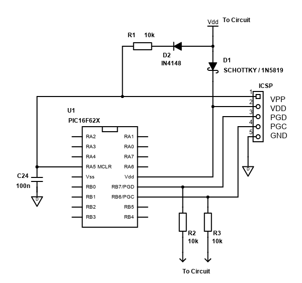
10k resistors are shown from the PGC and PGD pins to the rest of the circuit, which in some cases would allow you to use the pins both for programming and as I/O during normal operation. It's not guaranteed to work with all types of I/O though, for example driving an LED off these pins for example has no chance, unless you connect the LED via a transistor using the 10k resistor to its base. It's far easier to plan to dedicate these pins for ICSP if you can, and test if you can't before you build the final PCB.
The diode D1 isolates the PIC from the rest of the circuit power, otherwise your programmer will try and power the rest of the circuit when connected and will not program correctly. This should be a Schottky diode such as 1N5819 or BAT42 for minimal voltage drop. D2 isolates the programming voltage VPP from doing the same. A normal signal diode is fine here or use the same Schottky diode.
Interrupts
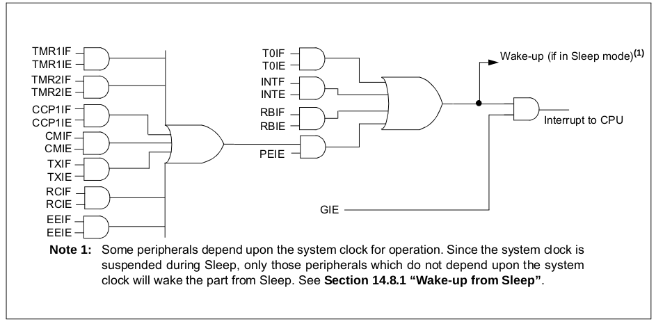
A feature I've pretty much always used in my builds are interrupts. The above shows a screenshot from the PIC16F62X datasheet with various interrupt flags and enable bits.
An interrupt can trigger your program to pause execution (wherever it is, unless its already in the interrupt routine) for handling the interrupt event. This allows a low latency reaction time to the event.
If using a C compiler, such as BoostC, the interrupt() function is automatically applied, but empty. This will add the required assembler / machine code for the entering and exiting the interrupt routine, but you must add checking of the interrupt flags and clearing of them yourself.
When building the interrupt routine - keep the code fast and minimal. You want the interrupt to be dealt with swiftly and the code returned to normal execution so that another interrupt is not blocked (so don't add delays in the interrupt routine).
For any interrupts to be processed, the global interrupt flag (usually called GIE) needs to be enabled. For peripheral interrupts (such as timers), PEIE also needs to be enabled.
Most interrupts can also be used to wake the PIC up from sleep state. Sleep is when code execution is paused, and power draw is very low (just a couple of micro-amps µA). This would allow battery saving by allowing the PIC to sleep when it is doing nothing but can be woken up by the press of a button connected to the external interrupt for example.
Whenever an interrupt occurs, the flag bit that got set to 1 to indicate which interrupt happened must be set back to 0 in your code once you've dealt with the interrupt - otherwise it can never occur again, or your code might run the routine for this interrupt again when another interrupt occurred.
External Interrupt(s)
On most PICs, RB0 is the external interrupt pin, or GP2 for the PIC12F675, but some PICs allow you to configure more than one (e.g., RB1, RB2).
The external interrupt must be set to interrupt on input direction change - falling edge or rising edge. This can be programmed and even changed during program flow. The registers/pins to enable the interrupt and clear the flag once dealt with varies per PIC.
For the external interrupt to work, you need to make sure the pin is set to an input pin (relevant TRIS register), the edge detection bit (e.g., INTEDG) is correct, the external interrupt is enabled (e.g., INTE) and the global interrupts are enabled (e.g., GIE).
On-Change Interrupt
This may also be referred to as PORTB Interrupt. This interrupt is similar to the external interrupt, but it will always trigger on any change (you cannot set the edge detection rising/falling).
Your PIC may or may not support it, and it is only relevant for some pins - for example RB4 to RB7 on the PIC16F62X.
If you need to know what pin caused the interrupt, you'll need to maintain a previous value of (say) PORTB in your code so you can compare the current vs prior and set the prior once you've completed that comparison.
For the on-change interrupt to work, you need to make sure the pin is set to an input pin (relevant TRIS register), the external interrupt is enabled (e.g., INTE) and the global interrupts are enabled (e.g., GIE).
Comparator Interrupt
If your external interrupt or on-change interrupts are already in use / not available and you need more, the comparator can be used to generate interrupts too. It is also capable of waking the PIC from sleep.
To generate an interrupt off a digital signal with the comparator, you can set one input to be at half the VDD supply voltage using two equal resistors as a voltage divider (so you get about 2.5V if VDD is 5V). Connect the output of the divider to (say) VIN+. The other input VIN- can be connected to your button/switch or whatever input is required and when the input is high, the comparator output (e.g., C1OUT) should be 0. When the VIN- is low, the comparator output is 1.
Some PICs can also have an internal comparator reference signal for VIN+, so you won't need the resistors. See the voltage reference module in the datasheet and how to set the register VRCON (for example).
Interrupts can be generated whenever there is a change in comparator output value. Do note though that the lag will be slower than the external interrupt time, and the voltage reference will consume current too, even when the PIC is sleeping.
Timer input/output pins
PIC microcontrollers can have several timers, and Timers 0 and 1 can both generate output signals on pins, as well as tick based on pin input signals.
This means if you have those pins for other I/O, you need to be careful of the timer settings to ensure that the timer does not override the pin with its own function.
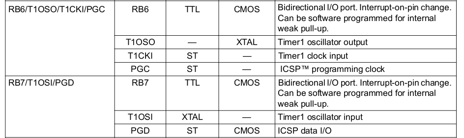
The main example is the timer 1 clocks. For example, on a PIC16F62x, RB6 and RB7 will cease to function as I/O if T10SCEN in T1CON (oscillator enabled) is set, regardless of the TRISB setting. Setting TMR1CS (counter mode) will also affect one of those pins, depending on T10SCEN. Timer 1 also won't run in counter mode unless you send pulses to the relevant pin.
Timer 0 can impact too. Setting T0CS in OPTION will affect RA4. Timer 0 won't run either, unless you send pulses to this pin.
Other PICs will use different pins and registers/bits for setting the timer options, so check the data sheet.
There is a useful timer calculator at Dring Engineering Services - IC Timer Calculator, but be aware that for timer 1 it does set T1OSCEN on, which will affect those T1OSI and T1OSO/T1CKI pins, so if you copy code from there, change T1OSCEN to 0!
Communications - USART / Serial Communications Interface (RS232)
Many PICs have hardware USART built in - but not all! The small PIC12F675 doesn't for example, and with such small code space building a software implementation will be a challenge, so pick your PIC carefully!
The first thing to note in your design is that hardware USART must use specific pins, commonly labelled RX/DT and TX/CK. These pins cannot be used for anything else, and no other pins can be used for hardware USART.
Also be warned that on some PICs, the pins are shared with other hardware modules. On many PIC18 devices, you cannot have hardware USART and hardware SPI (via the MSSP) on the same PIC, as the RX/DT pin for USART is also the SDO pin for SPI data out. Damn! Fortunately, implementing SPI in software is quite easy.
The USART output is TTL. In asynchronous mode, this can connect with Bluetooth modules such as the HC-06 module with a 9600 baud rate, though you'll need a 5V to 3.3V logic level conversion if your PIC has a VDD of 5V.
Asynchronous USART can also be made compatible with RS232 by using a chip such as the MAX232 to generate the higher voltage levels required, allowing the PIC to communicate with a PC or other equipment that has these decades old ports.
Using the hardware USART module will vary per PIC, so you'll need to read the datasheet. Simple send and receive code can be made with these BoostC examples...
Initialisation should be done at power on to initialise. Some global variables are needed too (these will consume RAM space, so choose the buffer size wisely).
This is an example for an asynchronous USART with a 4MHz oscillator frequency and a 9600 baud rate (which is the most compatible and reliable, but slow, however fine for a few bytes!).
char iRS232Index = 0;
char rs232Buffer[RX_BUFFER_SIZE];

void initialise() {
    ... snip ...

    trisc = 0xC0; // RC7 (Rx) and RC6 (Tx) are inputs
    // USART communications setup
    // SYNC = 0, BRGH = 1, BRG16 = 0
    // 4MHz Baud rate 9600 : ((10000000 / 9600) / 16) - 1 = 25
    spbrg = 25;
    txsta = 0x26; // 00100110 - 8 bit, transmit enable, async mode, high speed, TSR empty, 9bit (0)
    rcsta = 0x90; // 10010000 - serial port enabled, 8 bit reception, async mode continuous receive, no frame error, no overrun error
    baudcon = 0x42; // 01000010 - non-inverted, 8 bit generator, wake up on receive

    pie1.RCIE = 1; // Usart interrupt receive (no send interrupt)

    ... snip ...
}
The interrupt routine can be used to process receiving USART bytes. This is setup to flag TASK_RS232 once the line break character is received.
void interrupt(void) {
    ... snip ...
    // RS232
    // byte received interrupt
    if (pir1.RCIF && pie1.RCIE) {
        // pir1.RCIF is cleared automatically once rcreg is read
        if (rcsta.OERR) { // Overrun error rcsta.OERR
            rcsta.CREN = 0; // clear bit CREN
            rcsta.CREN = 1; // set bit CREN
        } else if (rcsta.FERR) {
            rs232Buffer[iRS232Index] = rcreg;
        } else {
            rs232Buffer[iRS232Index] = rcreg;
            // Read until line feed or EOT is detected
            if (!cTask.TASK_RS232) {
                while (!pir1.TXIF);
                if ((rs232Buffer[iRS232Index] == 10) || (rs232Buffer[iRS232Index] == 4)) {
                    TASK_RS232 = 1;
                    //iRS232Index = 0; // You can reset the buffer here, or leave it until bytes are processed in code (so you know the length of command)
                }
                // Otherwise increment buffer index for next byte received
                iRS232Index++;
            }
        }
    }
    ... snip ...
}
Sending a small amount of data can be done in blocking code.
// Send single character byte over rs232
void rs232SendByte(char c) {
    txreg = c;
    while (pir1.TXIF == 0); // Wait for byte to be transmitted
    while (txsta.TRMT == 0); // Wait for byte to be transmitted
}

// Send string over rs232
void rs232Print(unsigned char *s) {
      while (*s) {
        rs232SendByte(*s++);
    }
}
USART also has a synchronous mode. In this mode, data is half-duplex (transmit and receive must happen separately) and the TX/CK pin becomes a clock and RX/DT becomes a data state. Each bit is sent out through a rise and fall of the clock pin, similar to SPI and I2C but not compatible as SPI can send/receive at the same time and is MSB (most significant bit) first, and I2C usually requires ACK signals after each transmission.
Synchronous Serial Port (SSP) / Master Synchronous Serial Port (MSSP)
Some PICs (sadly, not enough) have hardware support for SPI (Serial Peripheral Interface) and I2C (Inter-Integrated Circuit). I2C may also be known as TWI (two-wire bus).
Many peripheral chips use these protocols, such as LCD/OLED displays, various sensors, A/D convertors, EEPROMS, shift registers and so on... the list is huge!
Using hardware modules is recommended as they are faster, and your code will be smaller (requiring less flash ROM) compared to implementing these protocols in software.
These SSP/MSSP modules must use specific pins, usually labelled SCK/SCL, SDI/SDA and SDO. You cannot use any other pins, and you cannot have hardware SPI as well as hardware I2C at the same time, so choose your external peripheral chips carefully so they all use the same bus.
These dedicated pins are also often shared with other hardware features in the same device. For example, many PIC18 devices I've seen, the SPI SDO pin conflicts with the USART RX/DT pin. The SCK/SCL and SDI/SDA pins also conflict with external interrupt pins INT0 and INT1, so some design requirements will leave you implementing software alternatives instead. PIC16 is better, but many of them do not have hardware SSP/MSSP.
Also note that pics with just SSP support are designed to receive data only when using the I2C protocol, and not master it. They can master SPI busses though. Select a PIC with an MSSP module if you want hardware I2C mastering.
SPI will usually require separate pins for 'chip-select' too. For sending SPI data, you can pick any I/O pin appropriate for this and implement in software pulling this line low for the relevant chip prior to sending data out via the MSSP. In receiver mode, there is a dedicated SS pin, which for PIC16 and PIC18 usually sits on an ADC input pin.
I2C
BoostC does have a built in software support, and this can be used to select hardware support too. I like to 'DIY' though, so below are samples of I2C mastering and receiving. The mastering example is for a PIC16F873 with MSSP module. Receiving is for a PIC16F77 with an SSP module.
Sender mode - sending data to an external chip or module
Below is a I2C sending sample for BoostC on a PIC16F873/PIC16F877 using MSSP with ACK support. Here, the PIC is the controller/host. Setup for other PICs should be similar. Your peripheral/device might require a different communication though, so read its datasheet and set the bits in SSPCON, SSPCON2, SSPSTAT, PIR2 appropriately.
You will also need to set TRISC (or appropriate port for the SDA/SCL pins) so that RC4/SDA and RC3/SCL are inputs (not shown).
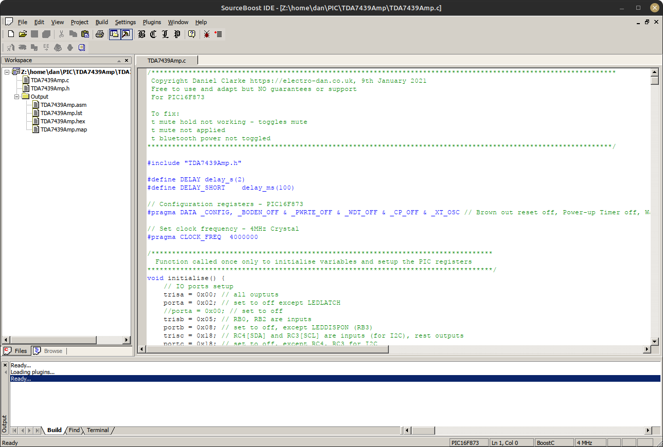
For a complete example, have a look at my TDA7439/STA540 amplifier software (download of the full source is here too).
/******************************************************
  Function called once only to initialise variables and
  setup the PIC registers
*******************************************************/
void initialise() {
    ... snip ...
    // Initialise I2C MSSP
    // Master 100KHz
    // TRISC set SCL and SDA pins as inputs above
    // SSPEN (I2C), CKP (clock polarity), SSPM3:SSPM0 -> 1000 = I2C Master mode,
    sspcon = 0x38; // I2C enabled (SSPEN), Master mode
    sspcon2 = 0x00;
    sspadd = 9; // Clock 100Khz @ 4Mhz Fosc - 4000000 / (4 * (9 + 1))
    sspstat.SMP = 1; // Slew rate disabled
    sspstat.CKE = 0;
    pir2.BCLIF = 0;
    ... snip ...
}

/***********************************************************************************
  I2C methods using MSSP
  https://www.hobbytronics.co.uk/tutorials-code/tutorials-microchip/hi-tech-c-i2c-master
************************************************************************************/
// i2c_Wait - wait for I2C transfer to finish
void i2cWait(void) {
    // sspcon2 bit 4 ACKEN: Initiate Acknowledge sequence on SDA and SCL pins and transmit ACKDT data bit. Automatically cleared by hardware.
    // sspcon2 bit 3 RCEN: Enables Receive mode for I2C
    // sspcon2 bit 2 PEN: Initiate STOP condition on SDA and SCL pins. Automatically cleared by hardware
    // sspcon2 bit 1 RSEN: Initiate Repeated START condition on SDA and SCL pins. Automatically cleared by hardware.
    // sspcon2 bit 0 SEN: Initiate START condition on SDA and SCL pins. Automatically cleared by hardware.
    // sspstat bit 3: Indicates that a START bit has been detected last
    while ((sspcon2 & 0x1F) || (sspstat & 0x04));
}

// i2c_Start - Start I2C communication
void i2cStart(void) {
    i2cWait();
    sspcon2.SEN = 1;
}

// i2c_Stop - Stop I2C communication
void i2cStop(void) {
    i2cWait();
    sspcon2.PEN = 1;
}

// i2cWrite - Sends one byte of data
void i2cWrite(char data) {
    i2cWait();
    sspbuf = data;
}

void i2cPrint(unsigned char *s) {
    i2cStart();
    i2cWrite(addr); // send i2c address
    while (*s) {
        i2cWrite(*s++);
    }
    i2cStop();
}
Receiver mode - reading data from a sender
This is when your PIC is the peripheral/device, and the host is elsewhere. This sample is for a PIC16F73/PIC16F77. Setup for other PICs should be similar. Your host might be using a different communication though, so read its datasheet and set the bits in SSPCON, SSPCON2, SSPSTAT, PIR2 appropriately.
You will also need to set TRISC (or appropriate port for the SDA/SCL pins) so that RC4/SDA and RC3/SCL are inputs (not shown).
I'm using a circular buffer here so the host can send data and fill the buffer whilst our peripheral/device PIC processes it, emptying the buffer as it goes. I add 0xFF to the buffer to indicate the end of the I2C command so I can identify, but if your host can send 0xFF then choose something else, or another method.
For a complete example, have a look at my DAB amplifier software (download of the full source is here too).
#define SSPSTAT_BIT_MASK 0b00101101 // Mask for I2C status bits
#define SSPSTAT_STOP_BIT_MASK 0b00111101 // Mask for I2C status bits including stop
// bit 0 BF: Buffer Full Status bit
// bit 2 R/W: Read/Write bit Information (I2C mode only)
// bit 3 S: START bit
// bit 5 D/A: Data/Address bit (I2C mode only)

#define I2C_BUFFER_SIZE 100

// State 1 - SSPSTAT bits: D_A = 0, S = 1, R_W = 0, BF = 1
#define I2CSTATE_1 0b00001001
// State 2 - SSPSTAT bits: D_A = 1, S = 1, R_W = 0, BF = 1
#define I2CSTATE_2 0b00101001
// State 3 - SSPSTAT bits: D_A = 0, S = 1, R_W = 1, BF = 0
#define I2CSTATE_3 0b00001100
// State 4 - SSPSTAT bits: D_A = 1, S = 1, R_W = 1, BF = 0
#define I2CSTATE_4 0b00101100
// State 5 - SSPSTAT bits: D_A = 1, S = 1, R_W = 0, BF = 0
#define I2CSTATE_5 0b00101000
// State Stop - SSPSTAT bits: S = 1, D_A = 1, R_W = 0, BF = 0
#define I2CSTATE_STOP 0b00110000

/******************************************************
  These variables and functions are for a circular buffer
*******************************************************/
enum BufferStatus {BUFFER_OK, BUFFER_EMPTY, BUFFER_FULL};
struct Buffer {
    unsigned char data[I2C_BUFFER_SIZE];
    unsigned char iHead;
    unsigned char iTail;
};
volatile struct Buffer i2cBuffer = {{0}, 0, 0};

enum BufferStatus i2cBufferWrite(unsigned char byteIn) {
    unsigned char iNextHead = (i2cBuffer.iHead == (I2C_BUFFER_SIZE - 1)) ? 0 : i2cBuffer.iHead + 1;

    if (iNextHead == i2cBuffer.iTail){
        return BUFFER_FULL;
    }
    i2cBuffer.data[i2cBuffer.iHead] = byteIn;
    i2cBuffer.iHead = iNextHead;
    return BUFFER_OK;
}

enum BufferStatus i2cBufferRead(unsigned char *byteOut) {
    if (i2cBuffer.iHead == i2cBuffer.iTail){
        return BUFFER_EMPTY;
    }
    *byteOut = i2cBuffer.data[i2cBuffer.iTail];
    i2cBuffer.iTail = (i2cBuffer.iTail == (I2C_BUFFER_SIZE - 1)) ? 0 : i2cBuffer.iTail + 1;
    return BUFFER_OK;
}

/******************************************************
  Function called once only to initialise variables and
  setup the PIC registers
*******************************************************/
void initialise() {
    ... snip ...
    // I2C communications setup
    sspcon.WCOL = 0; // No colision
    sspcon.SSPOV = 0; // No overflow
    sspcon.SSPEN = 1; // Enabled SDA/SCL pins
    sspcon.CKP = 1; // SCK release control - enable clock
    // 1110 = I2C peripheral/device mode, 7-bit address with START and STOP bit interrupts enabled
    sspcon.SSPM3 = 1;
    sspcon.SSPM2 = 1;
    sspcon.SSPM1 = 1;
    sspcon.SSPM0 = 0;

    sspadd = I2C_address << 1; // Address requested from the DAB module, should be shifted one bit to the left [ SSPSR<7:1> ]
    sspstat = 0; // Clear by default
    ... snip ...
}

/******************************************************
  Interrupt handler
*******************************************************/
void interrupt(void) {
    ... snip ...
    // I2C
    // SSP interrupt byte received
    if (pir1.SSPIF) {

        char i2cData;
        char i2cStatus;
        char i2cState;

        if ( sspcon.SSPOV == 1 ) {
            // Test if we have an overflow condition and clear it
            i2cData = sspbuf; // Do a dummy read of the SSPBUF
            sspcon.SSPOV = 0; // Clear the overflow flag
        } else {
            // Mask the status bits out from the other unimportant register bits
            // SSPSTAT_BIT_MASK  0b00101101
            // bit 0 BF: Buffer Full Status bit
            // bit 2 R/W: Read/Write bit Information (I2C mode only)
            // bit 3 S: START bit
            // bit 5 D/A: Data/Address bit (I2C mode only)
            i2cStatus = ( sspstat & SSPSTAT_BIT_MASK );

            if ( (i2cStatus ^ I2CSTATE_1 ) == 0 ) {
                // State 1 - SSPSTAT bits: S = 1, D_A = 0, R_W = 0, BF = 1
                // State 1: Master Write, Last Byte was an Address
                // Do a dummy read of the SSPBUF
                i2cData = sspbuf;
            } else if ( (i2cStatus ^ I2CSTATE_2 ) == 0 ) {
                // State 2 - SSPSTAT bits: S = 1, D_A = 1, R_W = 0, BF = 1
                // State 2: Master Write, Last Byte was Data
                // Read from SSBUF
                i2cData = sspbuf;
                i2cBufferWrite(i2cData);
            }
        }

        // If stop condition:
        // State Stop - SSPSTAT bits: D_A = 1, P = 1, S = 0, R_W = 0, BF = 0
        if ((( sspstat & SSPSTAT_STOP_BIT_MASK ) ^ I2CSTATE_STOP) == 0 ) {
            // End of command - write FF to indicate it
            i2cBufferWrite(0xFF);
            // Flag the task scheduler that there is data to process
            cTask.TASK_I2C_RECV = 1;
        }

        pir1.SSPIF = 0; // Clear interrupt flag
    }
    ... snip ...
}

/******************************************************
  Called after I2C communcation received to process the
  bytes in the buffer
*******************************************************/
void i2cProcess() {

    unsigned char iReadData;
    unsigned char iProcessing = 0; // 0 for looking, 1 for functions, 2 for text data, 3 for custom data

    // Keep reading until BUFFER_EMPTY
    // i2cBufferRead moving the start position in the buffer for us
    while (i2cBufferRead(&iReadData) == BUFFER_OK) {
        if (iReadData == 0xFF) {
            // Finished command
            iProcessing = 0;
        } else if (iProcessing == 0) {
            // Process here
        }
    }
}
EEPROM - Electrically Erasable Programmable Read-Only Memory
Some PICs - but not all - have an EEPROM available. Check your PICs datasheet as a major PIC such as the PIC16F77 does not have it (because it is intended to be a peripheral), whereas the PIC16F877 does have it.
This allows you to save a few bytes data that will get retained in the PIC, even when power is completely removed. EEPROM is slower and far more write limited than today's modern Flash memory. Endurance should still be 100K at minimum, per byte (though double check the datasheet). This would last hundreds of years if you wrote only once per day. If you wrote once an hour though, it's less than 12 years. This is why clock radios don't use EEPROM to remember the time/alarms after a power cut (that and EEPROM costs more), instead relying on RAM and a 9V battery.
Therefore, you should only write to the EEPROM if the bytes you want to save after power removal have actually changed, and less frequently than you need.
An example is my Hi-Fi LM3886 amplifier which uses a hardware AC monitor to detect when the power has been removed and saves the amplifier's state to EEPROM at that time. There is enough charge left in the DC smoothing capacitors after power off for the PIC to save the data to EEPROM - it only needs at most 8 milliseconds per byte after all. When the power is on, nothing needs to be saved to the EEPROM.
Here is some sample save and read code. The save does a read and does not write if the data is the same. I also use address 0 to indicate whether the EEPROM has been saved to, otherwise the EEPROM is probably full of 0xFF bytes if you've just programmed the chip.
/***********************************************************************************
  EEPROM read and write methods
************************************************************************************/
void saveData() {
    char didWrite = 0;
    // only write value if it is different
    didWrite += eepromWrite(1, iVolume);
    didWrite += eepromWrite(2, iAttenuateL);
    didWrite += eepromWrite(3, iAttenuateR);
    didWrite += eepromWrite(4, iBass);
    didWrite += eepromWrite(5, iMid);
    didWrite += eepromWrite(6, iTreble);
    didWrite += eepromWrite(7, iActiveInput);

    if (didWrite)
        eepromWrite(0, 10); // To indicate EEPROM has been saved
}

char eepromWrite(char address, char data) {
    char didWrite = 0;
    if (eepromRead(address) != data) {
        char intconsave = intcon;

        // Load address and data
        eeadr = address;
        eedata = data;

        eecon1.EEPGD = 0; // Point to DATA memory
        eecon1.WREN = 1; // Enable writes

        // Required write sequence
        intcon = 0;
        eecon2 = 0x55; // Write 55h
        eecon2 = 0xAA; // Write 0AAh
        eecon1.WR = 1; // Set WR bit to begin write
        intcon = intconsave;
        eecon1.WREN = 0; // Disable writes on write complete (EEIF set)
        while(!pir2.EEIF); // Wait for the interrupt bit EEIF to be set
        pir2.EEIF = 0; // Clear EEIF
        didWrite = 1;
    }
    return didWrite;
}

/******************************************************
  Function to read the current variables from ROM
*******************************************************/
void readData() {
    // Read initial values from EEPROM
    // Do not read other variables if the EEPROM has not been saved before
    // as all default will be 0xFF
    if (eepromRead(0) == 10) {
        iVolume = eepromRead(1);
        iAttenuateL = eepromRead(2);
        iAttenuateR = eepromRead(3);
        iBass = eepromRead(4);
        iMid = eepromRead(5);
        iTreble = eepromRead(6);
        iActiveInput = eepromRead(7);
    }
}

char eepromRead(char address) {
    // Load address
    eeadr = address;
    eecon1.EEPGD = 0; // Point to DATA memory

    // Read, data is available in eedata the next cycle.
    eecon1.RD = 1;

    // Return value
    return eedata;
}
PWM - Pulse Width Modulation
Hardware PWM may - or may not again - be built into the PIC. Pins that support it can vary. On the PIC16F62X, only the RB3/CCP1 pin supports PWM output, for example. PIC16F87X has PWM two pins (RC2/CCP1 and RC1/CCP2).
PWM is also on the same pins as the Capture/Compare modules.
The PWM frequency will run off a timer, such as timer 2. So, bear that in mind as you'll have one less timer for your code, unless you can still use it for generating interrupts at the same frequency as PWM.
PWM can be used to control LED brightness or motor speed for example. It will consist of a frequency (period), and a duty cycle (how long within the period the pulse is on). The output device will then average it.
This is an efficient form of speed control, as using potentiometers or variable voltage regulators will output the difference as heat.
I've not yet used PWM on PIC microcontrollers, so I don't have any other tips/samples. It's an interesting feature to use though and if I do use it, I'll add more here.
Summary
Despite its age, and huge competition from the likes of Arduino and others, the PIC microcontroller system continues to interest me and because there is a great variety of chips in easy to use DIP packages, it really lets me DIY my own circuits exactly as I want.
In my home I currently have three amplifiers where PIC microcontrollers are at the heart of their functionality, a PIC to decode a DAB radio module to my own OLED display, a PIC handling subwoofer power and muting, a timer in the bathroom for switching off the heated towel rack, and two thermometers.
All work extremely well thanks to the simplicity and all were actually fun to build, both to learn and left a great sense of achievement when 'completed' (in quotes there, because I sometimes add more features or optimisations!). It not only enhances knowledge of electronics and hardware, but software too, and how to write efficient code.
There will definitely be more projects in future using a PIC microcontroller!
References and more reading:
SourceBoost Technologies - low cost, high performance cross compilers
UsbPicProg - Open Source Microchip PIC programmer
Hobby Electronics - Hi-Tech C I2C Master
Learning about Electronics - How to Connect a
In-Circuit Serial Programming (ICSP) Interface
SourceBoost I2C Slave Example
Microchip Forums - Interrupt on I2C stop condition
Microchip Forums - I2C Slave mode - detect STOP bit
electroSome - I²C Communication with PIC Microcontroller – MPLAB XC8
Dring Engineering Services - IC Timer Calculator and Source Code Generator
Hackaday - Embed With Elliot: Going ‘Round With
Circular Buffers