
Simple PIC Microchip DS18B20 Thermometer with 4-digit display using TM1637
Having built a PIC Mircochip based thermometer almost a year ago, I wanted to use some spares to build another version for another room.
To vary the implementation a bit and spend less time on the implementation, I decided to simplify the job. This version uses a cheap module for the 4-digit 7 segment display which has a TM1637 chip on it, instead of driving the display directly. It also uses the small and cheap PIC12F675, and the circuit is built on stripboard instead of a custom PCB. Time to code and build for me was no more than about 5 hours.
This version of the thermometer is more beginner friendly, as the code is far less, and no custom PCB is required as it's easily built on standard Stripboard/Veroboard.
Again, you can surely buy a dedicated digital thermometer very cheap, but that's boring! As I had all the parts and a little time anyway, here is my simple thermometer project!
Recommended Experience : Beginner/Intermediate, knowledge of programming, microprocessor programmer
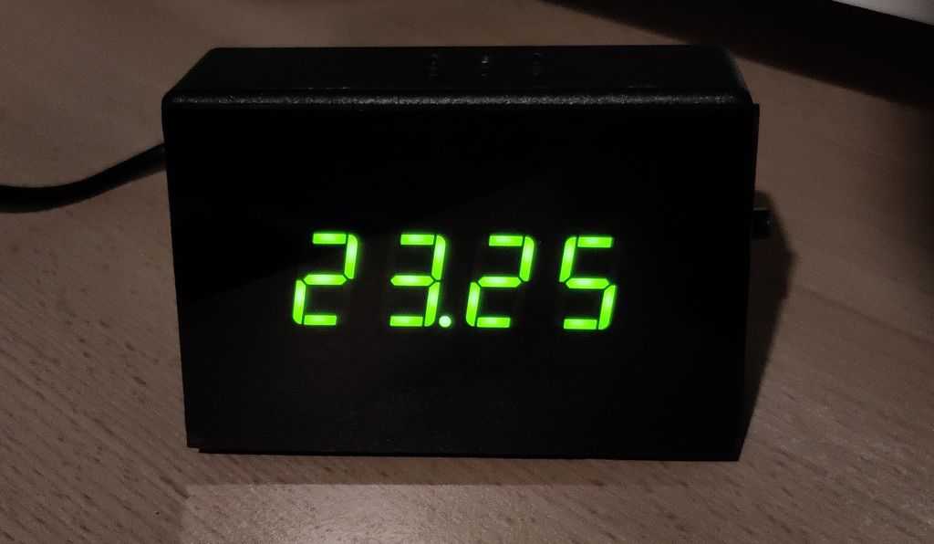 Above: View of thermometer operating
Hardware
The hardware was going to be coming from my parts collection, so I didn't have to order anything at all to proceed immediately with the project.
The components I selected are:
- PIC12F675 - a simple PIC that I had, which has just 1K words of flash program memory, can run up to 20MHz and has 6 I/O pins.
- DS18B20 - a digital thermometer in a small TO-92 package
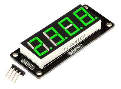
- TM1637 - a module with four 7-segment LED displays
- 1x 4k7 ohm resistor - cheap 5% carbon resistor will do
- 1x 10uF electrolytic capacitor, 1x 100nF ceramic capacitor
- 8-pin DIP socket for the PIC12F675
- 2-pin DC power connector
- An old 5V 1A DC adaptor from a bygone network router or switch
The hardware is very minimal as most of the work would be done in software on the microprocessor, and the hardware of the DS18B20 and TM1637. I picked a PIC12F675 as a simple microcontroller that is easy to assemble into a circuit. A PIC12F629 would also work as that's basically the same just with no ADC (which isn't needed here).
This project also uses the DS18B20. It's simple to wire up with only three connections needed, and a resistor.
Warning: - the DS18B20 is widely faked. I did purchase a couple off eBay and whilst the first one I tested was fairly accurate, the second was reading almost 3 degrees Celsius lower! I suggest you buy them from well-known retailers, even though they are significantly more expensive, you'll get thermometers which are far more accurate.
Compared to my other thermometer, the LED display is handled by the TM1637 module. These are very cheap and available on eBay, Amazon, AliExpress and the like. Despite the low cost, they are good quality. Pay attention to what you are ordering though as some have a colon on the display instead of dots (making them ideal for clocks, but not a thermometer). You can also get 6 digit versions. The module contains pull-up resistors, decoupling capacitors on the PCB itself, so nothing else is needed to make a direct connections to the microcontroller.
The rest of my parts were just one resistor, two capacitors, an IC socket and headers. Even someone fairly new to the electronics hobby probably has them!
The whole lot operates off 5V. With the PIC running at 4MHz and the TM1637 being quite energy efficient, current draw is just 45mA at full brightness. That will be too much for running off 3x AA batteries (probably they'll last just 2 to 3 days), but fine for running off a small 5V mains adaptor, or USB.
The complete system is placed in a project box - ABS Box H2855 I got early 2018 during the sad closure of Maplin stores.
Schematic and PCB
Below is a schematic of the solution. Super simple!
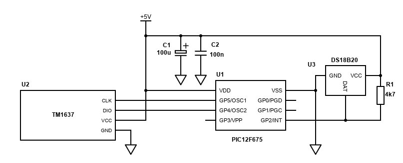
Challenges with this are minimal, just ensure you orientate the PIC correctly, ensure positive is positive (+) on the PSU etc.
Below is a stripboard layout suggestion, and what I went with:
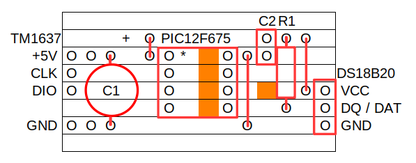
The layout is very simple. The tracks will need to be cut with a stripboard cutting tool, small drill bit or modelling knife where the dark orange squares are though. A cut of four traces where the PIC DIP is, and an additional cut to separate the VCC of the DS18B20 from the PIC pin.
I used headers and DuPont connectors in my build to connect the TM1637 module and the power supply input. I used 2.54mm spaced socket headers to push the DS18B20 into. All these can be soldered directly if you prefer though.
This layout does not allow programming of the PIC in-circuit, but since I've not used the VPP, PGC and PGD pins it would be easy to add an ICSP header, you just need to isolate the VDD from the rest of the circuit via a diode.
Since I suspected, I wouldn't need to program the PIC many times, I decided instead to just use an 8-pin socket and I'd lift the PIC out of the circuit and into a programmer for flashing the updated code on to it. Then lift it back out of the programmer and back into my circuit for testing.
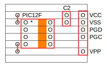
A simple adaptor to connect to my UsbPicProg is easily built on stripboard, so I did that too and below is the layout:
Finally, a DC power connector was included so I could power the project from an another old ethernet router PSU (5V 1A). It would also have worked fine off a USB cable/psu too though. The 5V in is decoupled with a 100uF and 100nF capacitor (anything 10uF or more will be fine too).
Software
PIC microprocessors are 'supposed' to be programmed in its assembler language and given how simple this implementation is I could have done it in assembler. I find it time consuming and hard to pick up, read and adjust later. Instead, I use C, and since 2005 SourceBoost has been my favourite product for PIC programming.
SourceBoost is now free (donation recommended), though I brought a license a long time ago. Their Chameleon compiler is also free, but this program easily falls under the 2k limit of the BoostC free license.
My source code is available on github.com.
Most of the hard work is actually in the peripherals. The DS18B20 takes care of ADC conversion and gives a digital readout of temperature on a serial bus. The TM1637 takes care of multiplexing the four 7-segment displays and the segments to display is written to it using another serial bus.
The work the PIC must do is controlling the serial buses to both devices and converting the temperature readings from the DS18B20 to segments on the TM1637 display, at occasional intervals.
Per my previous project, communicating with the DS18B20 is quite tricky, but I had good code from that from the time and this project uses pretty much the same routines, though I've simplified them a little to use delays rather than Timer2.
The TM1637 involves writing new code, but not really. The code I've used is pretty much based off the Arduino library available on GitHub but simplified to do only what's needed.
Configuration and initialisation
PIC microcontrollers need to be configured and initialised before your program runs. That's because there are so many options for each pin and how the controller runs.
First there is configuration. This is set only during programming and cannot be altered during runtime. The PIC12F675 only has one CONFIG register, with 11 bits to consider settings or clearing.
//Target PIC12F675 configuration word
#pragma DATA _CONFIG, _PWRTE_ON & _WDT_OFF & _INTRC_OSC_NOCLKOUT & _CPD_OFF & _CP_OFF & _MCLRE_OFF & _BODEN_ON
The configuration is set by the SourceBoost C macros. If you're interested, the #define directives are in C:/Program Files/SourceBoost/include/PIC12F675.h. My configuration is explained in the table below:
| Bit | C macro | My setting | Reason |
|---|---|---|---|
| bit 13-12 BG1:BG0 | 11 = Highest bandgap voltage | Left as default - this setting does not matter in this program | |
| bit 8 CPB | _CPD_OFF | 1 = Data memory code protection is disabled | I'm not building a commercial product - code doesn't need protecting |
| bit 7 CP | _CP_OFF | 1 = Program Memory code protection is disabled | I'm not building a commercial product - code doesn't need protecting |
| bit 6 BODEN | _BODEN_ON | 1 = Brown-out Detect enabled | Not too critical but I'd rather the PIC resets itself when the voltage is too low |
| bit 5 MCLRE | _MCLRE_OFF | 0 = GP3/MCLR pin function is digital I/O, MCLR internally tied to VDD | I've no need to use MCLR to reset the PIC and I'd rather have that pin as an input/output. This saves requiring at least a resistor in the circuit. |
| bit 4 PWRTE | _PWRTE_ON | 0 = Power-up Timer enabled | The power supply needs a moment to stabilise. Enabling the power-up timer ensures the program starts reliably. |
| bit 3 WDT | _WDT_OFF | 0 = Watchdog Timer disabled | I do not want the Watchdog timer to reset the PIC when the code deliberately delays. |
| bit 2-0 FOSC2:FOSC0 | _INTRC_OSC_NOCLKOUT | 100 = INTOSC oscillator: I/O function on GP4/OSC2/CLKOUT pin, I/O function on GP5/OSC1/CLKIN | This sets the clock configuration. Here I'm telling the clock to use the internal 4MHz oscillator, and still allow the GP4 and GP5 pins for I/O functions, as my circuit has no peripherals that need to be driven off the same clock. |
Initialisation is done within the program itself, when the PIC resets. I'll be performing several tasks here and to make the code easier to follow, all initialisation lines are in an initialise() method.
/*********************************************************************************************
  Function called once only to initialise variables and
  setup the PIC registers
*********************************************************************************************/
void initialise() {
    // GP0 = OUT: N/C
    // GP1 = OUT: N/C
    // GP2 = IN/OUT: DS18B20
    // GP3 = OUT: N/C
    // GP4 = IN/OUT: TM1637 DIO
    // GP5 = IN/OUT: TM1637 CLK
    gpio = 0b00000000; // all pins off by default
    trisio = 0b00110100; // TM1637 pins and DS18B20 pin are inputs

    ansel = 0; // configure A/D inputs as digital I/O
    cmcon = 7; // compartor off

    option_reg = 0;
    option_reg.NOT_GPPU = 1; // disable pull ups

    // Setup timer 1, used to periodically ask for a temperature reading, and receive it after sending - 262ms
    // Timer calculator: http://eng-serve.com/pic/pic_timer.html
    // Timer 1 setup - interrupt every 262ms seconds 4MHz
    t1con = 0;
    t1con.T1CKPS1 = 1;   // bits 5-4  Prescaler Rate Select bits
    //t1con.T1CKPS0 = 0;   // bit 4
    //t1con.T1OSCEN = 0;   // bit 3 Timer1 Oscillator Enable Control bit 1 = off - this should be cleared so we can use RB7 and RB6 as outputs
    t1con.NOT_T1SYNC = 1;    // bit 2 Timer1 External Clock Input Synchronization Control bit...1 = Do not synchronize external clock input
    //t1con.TMR1CS = 0;    // bit 1 Timer1 Clock Source Select bit...0 = Internal clock (FOSC/4)
    t1con.TMR1ON = 1;    // bit 0 enables timer
    pie1.TMR1IE = 1; // Timer 1 interrupt enable
    pir1.TMR1IF = 0; // Clear timer 1 interrupt flag bit

    // No task at initialisation
    cTask = 0;

    // Enable interrupts
    intcon.GIE = 1;
    intcon.PEIE = 1;
}
This is doing several steps:
- Set the gpio resister. This sets the default output/reading of the pins. Here the default I want to all be binary 0
- Set the trisio register. This sets the input/output direction for each pin. Binary 1 means the pin is an input. GP2, GP4 and GP5 are set as inputs. The pin will float, and the electrically pulled high (binary 1) by the pull-up resistors (that's the 4k7 resistor added in the circuit for the DS18B20, and the 10k pull-up resistors built in on the TM1637 module.
- Set ansel to 0. This makes all pins digital rather than being an ADC pin
- Set cmcon to 7. This sets the comparator function off for all pins. See page 37 of the datasheet. CM2:CM0 = 111 is what we need to be able to use GP0, GP1 and GP2 as normal I/O pins
- Set option_reg to 0, except the GPPU bit as internal pull up resistors I want disabled (pull-up is by external resistors)
- Set t1con as well as associated interrupt bits in pie1 and pir1 - see timer 1 setup below
- Set cTask to zero so the task scheduler does nothing to begin with
- Set intcon GIE and PEIE bits to 1. This enables interrupts to be processed (including the timer 1 interrupt)
As part of the power on routine I also call convertTemp(); and tm1637UpdateDisplay(); once without reading an actual temperature. This will display 0000 on the display and allows me to verify that the display is working when powered on. These routines are not strictly necessary and can be removed, but they are helpful when testing.
After initialisation, the PIC will enter into an endless while loop. Each time this loop runs a check will be made to see if there is a task to be performed. This is a simple task scheduler.
This task scheduler allows two tasks - TASK_TIMER1_START and TASK_TIMER1_READ. These tasks are set by the interrupt routine when the timer counts and overflows a certain number of times. It's good practice to run the code to do work in the main routine and keep logic in the interrupt routine simple and fast.
So essentially the PIC interrupt routine will run. If a condition is met and a task needs to be run, the TASK_TIMER1_START will be set in the interrupt routine, and that routine will finish. The PIC will then return execution to the main loop where the TASK_TIMER1_START condition is now met, running the methods oneWireBusReset(); and startTemp();, and then setting the task TASK_TIMER1_START back to zero.
In this program, tasks are executed only via timer 1, so I'll explain that next...
Timer 1
In my previous project, I used three timers - timer0 for multiplexing the display, timer1 for temperature reading intervals and timer2 for handling delays in the one-wire serial communication (to avoid blocking display multiplexing during that time).
This project just uses timer1 to control the interval that I ask for a temperature conversion and read it after. As the PIC does not need to multiplex the displays (TM1637 does that for us), the other timers are not needed.
Timer 1 was used for two purposes:
- Counting a delay between asking the DS18B20 to convert a temperature and reading it after (needs to be at least 750ms
- An interval for refreshing temperature readings, which I picked as around 30 seconds
Timer 1 is used because the timer behaves as a separate unit in the PIC, running at the same time the code is. Without using this I would have to rely on doing delays in the main execution of the code, which is tricky to do when running other code.
You can't get 750ms interrupt from timer1 directly. The highest overflow time on a 4MHz clock is 524.288ms (1/8 prescaler), so the best thing to do is pick a value that divides nicely. On a 4MHz speed and a 1:4 prescaler, timer 1 will interrupt every 262ms. Once the interrupt occurs three times, then more than 750ms has passed (786ms) and the temperature can be retrieved from the DS18B20.
Here's my initialisation code again for the timer.
    // Setup timer 1, used to periodically ask for a temperature reading, and receive it after sending - 262ms
    // Timer calculator: http://eng-serve.com/pic/pic_timer.html
    // Timer 1 setup - interrupt every 262ms seconds 4MHz
    t1con = 0;
    t1con.T1CKPS1 = 1;   // bits 5-4  Prescaler Rate Select bits
    //t1con.T1CKPS0 = 0;   // bit 4
    //t1con.T1OSCEN = 0;   // bit 3 Timer1 Oscillator Enable Control bit 1 = off - this should be cleared so we can use RB7 and RB6 as outputs
    t1con.NOT_T1SYNC = 1;    // bit 2 Timer1 External Clock Input Synchronization Control bit...1 = Do not synchronize external clock input
    //t1con.TMR1CS = 0;    // bit 1 Timer1 Clock Source Select bit...0 = Internal clock (FOSC/4)
    t1con.TMR1ON = 1;    // bit 0 enables timer
    pie1.TMR1IE = 1; // Timer 1 interrupt
    pir1.TMR1IF = 0; // Clear timer 1 interrupt flag bit
This 262ms timer can also be used to periodically refresh the temperature. My preference was every 30 seconds to check the temperature - this is a compromise between wanting to see frequent changes in room temperature, but not causing the DS18B20 to heat/wear prematurely (leading to inaccuracies in temperature readings). 262ms multiplied by 114 gives just over 29868ms - that's just under 30 seconds. Add on the 3 for the 750ms count earlier, and the temperature read can be made after 117 interrupts.
/*********************************************************************************************
  interrupt()
  Interrupt handler
*********************************************************************************************/
void interrupt() {
    // Handle timer1 interrupt - delay counter
    if (pir1.TMR1IF && pie1.TMR1IE) {
        // timer 1 will interrupt every 262ms with a 1:4 prescaler at 4MHz
        // We'll ask for the temperatute every 30 seconds
        // Into 30 seconds, 262ms goes 114 times (roughly)
        if (iTimer1Count == TIMER_1_INTERVAL) {
            // If the number of tasks to perform is less than the limit,
            // then add this task to the task array
            cTask.TASK_TIMER1_START = 1;
        }
        // just over 750ms after asking for temperature, it should be ready, so get the reading
        // 0.75 seconds is three more ticks above TIMER_1_INTERVAL
        if (iTimer1Count >= TIMER_1_INTERVAL + 3) {
            iTimer1Count = 0;
            // If the number of tasks to perform is less than the limit,
            // then add this task to the task array
            cTask.TASK_TIMER1_READ = 1;
        }
        // Count the number of times this timer overflowed
        iTimer1Count++;
        // Clear interrupt flag
        pir1.TMR1IF = 0;
    }
}
The TASK_TIMER1_START flag is set after just under 30 seconds (114 timer interrupts) and this will pass the execution on to the main() routine, which will ask oneWireBusReset(); and startTemp() routines to run in turn. Three further interrupts (114 + 3), about 750ms later, and TASK_TIMER1_READ will be flagged - causing the main() to ask the readTemp() routine to run. The iTimer1Count variable is reset at this point, allowing the timer to accurately interrupt again after another 114 counts (30 seconds).
TM1637
The TM1637 module is a simple display that may either be four or six digits. It may also have button inputs.
It offers convenience for projects. This is because soldering up all those pins, with resistors and driving transistors for multiple seven segment displays is quite a job. After that, you then get the software job of having to multiplex them. I did do it the hard way for my first digital thermometer, but this time I went the easier way.
The TM1637 uses a custom data protocol to receive data from the leader microcontroller. It's very similar to I2C / TWI, but it cannot really sit on a hardware I2C bus with other peripherals. It's not addressable, and it also cannot be daisy-chained.
Various libraries out there use it by bit-banging the output, including the popular Arduino library. Since bit-banging would be the most common way to use it, I'll also do the same.
Two data pins are needed to drive the TM1637 - a data line, and a clock line (just like I2C). The TM1637 includes pull-up resistors on the module itself, so we can think of the pins being in two states: on and off (1 or 0), where 'on' means the pin is configured as an input and is therefore pulled up to 5V by the resistor, and 'off' means the pin is configured as an output and driven to 0V by the microcontroller.
Implementing the bit-banging protocol for the TM1637 involves a pattern:
- Start condition - pulling the data line low for 100µs
- Writing out each byte - one bit at a time, LSB first, using the clock line to output each bit
- Stop condition - pulling the data line low for 100µs, then releasing the clock and data lines
In order to understand the code, some variables have been configured in the .h header file:
#define tm1637dio (gpio.4)
#define tm1637clk (gpio.5)
#define tm1637dioTris (trisio.4)
#define tm1637clkTris (trisio.5)
This is basically added references for the pin direction (TRIS input/output) and state (GPIO), which will be used int eh methods. Should you have a different type of PIC that refers to its IO as ports, you can replace those as needed e.g., portb / trisb.
Here are the snippets of code for each part of the pattern:
The start condition is simple - simply ensure the port direction is OUTPUT (tris=0) and state is LOW (IO = 0), then delay 100µs.
/*********************************************************************************************
 tm1637StartCondition()
 Send the start condition
*********************************************************************************************/
void tm1637StartCondition() {
    tm1637dioTris = 0;
    tm1637dio = 0;
    delay_us(100);
}
Writing data is a little more complex, but still a simple bit-bang operation.
It starts in a loop, which executes eight times. On each pass of the loop:
- Ensure the clock is set as an OUTPUT and state is OFF, then wait 100µs. This makes the clock line low to indicate the start of sending a bit.
- Now output the data state. Each bit of the byte needs to be checked, from the least significant bit first. The left-most bit is checked using bWrite & 0x01. If that bit is set, then set the data line as an INPUT. This indicates a state of ON (as the pull-up resistor will pull the line up to 5V). Otherwise, set the data line to an OUTPUT with state is OFF.
- Wait 100µs
- On the next loop, we need to check the next bit in the input byte, so shift all the bits to the right using bWrite >> 1
- The clock must go high again, so set the clock pin direction as INPUT, then wait another 100µs
After sending all eight bits of a byte, there is an ACK sequence. Actually, I never succeeded with the ACK code, so this part of the code does what it needs in the sequence, but something is off with either the timing or the module. Despite this, the display responds to the bytes it's sent perfectly.
The ACK sequence written though is currently:
- Send the clock pin low (set direction as OUTPUT, set state OFF)
- Set the data pin to an input (set direction as INPUT)
- Delay 100µs
- Send the clock pin high (set direction as INPUT)
- Delay 100µs
- Test the data pin - if it is still high, then no ACK, so set the data pin low
- Delay 100µs
- Send the clock pin low (set direction as OUTPUT, set state OFF)
- Delay 100µs
/*********************************************************************************************
 tm1637ByteWrite(char bWrite)
 Write one byte
*********************************************************************************************/
char tm1637ByteWrite(char bWrite) {
    for (char i = 0; i < 8; i++) {
        // Clock low
        tm1637clkTris = 0;
        tm1637clk = 0;
        delay_us(100);

        // Test bit of byte, data high or low
        if ((bWrite & 0x01) > 0) {
            tm1637dioTris = 1;
        } else {
            tm1637dioTris = 0;
            tm1637dio = 0;
        }
        delay_us(100);

        // Shift bits to the right
        bWrite = (bWrite >> 1);
        // Clock high
        tm1637clkTris = 1;
        delay_us(100);
    }

    // Wait for ack, send clock low
    tm1637clkTris = 0;
    tm1637clk = 0;
    // Make data an input
    tm1637dioTris = 1;
    tm1637dio = 0;
    delay_us(100);

    // Clock high
    tm1637clkTris = 1;
    delay_us(100);
    char tm1637ack = tm1637dio;
    if (!tm1637ack) {
        tm1637dioTris = 0;
        tm1637dio = 0;
    }

    // Clock low
    delay_us(100);
    tm1637clkTris = 0;
    tm1637clk = 0;
    delay_us(100);

    return 1;
}
For finishing up, a stop condition needs to be sent. This method simply brings the data line low for 100µs, then release both the clock, then after another 100µs, release the data line too.
/*********************************************************************************************
 tm1637StopCondition()
 Send the stop condition
*********************************************************************************************/
void tm1637StopCondition() {
    // Data low
    tm1637dioTris = 0;
    tm1637dio = 0;
    delay_us(100);
    // Release clk
    tm1637clkTris = 1;
    //tm1637clk = 1;
    delay_us(100);
    // Release data
    tm1637dioTris = 1;
    delay_us(100);
}
To display some numbers, we'll need to send several bytes to the TM1637:
- The first is 0x40 - to indicate command to display data
- Then write 0xC0, followed by the four bytes (characters) we want to display
- Then write 0x88 + brightness (in my configuration this is 0x88 + 7, or 0x8F, for full brightness pulse width 14/16)
The bytes that are sent to the display come from an array - tm1637Data. This doesn't have the actual numbers in them, but it instead is a translated byte indicating what segments to light on the actual display. For example, to display the number '1' on the display, two segments need to be lit only - segments b and c. This means sending the byte 0x06 - or 0000 0110. Bits 1 and 2 are set (ON) indicating to light these segments only. For the number '2', segments a, b, g, e and d - so that's 0101 1011 (that's 0x5B in hex). The array tm1637DisplayNumtoSeg in the .h file holds this translation. The most significant bit (0x80) is used to indicate whether the decimal point is lit or not.
The tm1637UpdateDisplay method takes care of writing these bytes of the TM1637.
/*********************************************************************************************
 tm1637UpdateDisplay()
 Publish the tm1637Data array to the display
*********************************************************************************************/
void tm1637UpdateDisplay() {
    // Write 0x40 [01000000] to indicate command to display data - [Write data to display register]
    tm1637StartCondition();
    tm1637ByteWrite(tm1637ByteSetData);
    tm1637StopCondition();

    // Specify the display address 0xC0 [11000000] then write out all 4 bytes
    tm1637StartCondition();
    tm1637ByteWrite(tm1637ByteSetAddr);
    for (char i = 0; i < tm1637MaxDigits; i++)
        tm1637ByteWrite(tm1637Data[i]);
    tm1637StopCondition();

    // Write 0x80 [10001000] - Display ON, plus brightness
    tm1637StartCondition();
    tm1637ByteWrite((tm1637ByteSetOn + tm1637Brightness));
    tm1637StopCondition();
}
Below is a pulse view capture of the transmission.
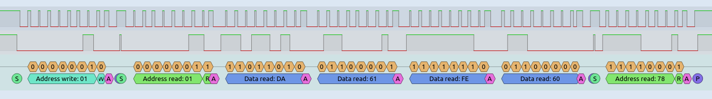
I've used the I2C decoder to translate the commands, but of course the bytes are inverted as I2C is MSB first, whereas the TM1637 protocol is LSB first. Therefore, the bits sent are:
- 0x01 (W) = 0x40 [0010 0000] - this is the "write data to display register"
- 0x01 (R) = 0xC0 [1100 0000] - this is the display address
- 0xDA = 0x5B [0101 1011] - light segments a,b,d,e,g - the number '2'
- 0x61 = 0x86 [1000 0110] - light segments b,c and the decimal point - the number '1.'
- 0xFE = 0x7F [0111 1111] - light segments a,b,c,d,e,f,g - the number '8'
- 0x60 = 0x06 [0000 0110] - light segments b,c - the number '1'
- 0x78 (R) = 0x8F [1000 1111] - turn the display ON, with brightness 14/16
The whole sequence of instructions takes 22.2ms - pretty slow but doesn't matter in this project. If you're project is more advanced though I suspect the delays can be reduced. If you remove the noise suppression capacitors from the module, the delays could be shorter too. Removing these capacitors would require the lead from the microcontroller to the TM1637 to be short though.
DS18B20 and the Dallas/Maxim One-Wire Protocol
Note: This section is largely a repeat of my other PIC thermometer arcticle.
The DS18B20 is a simple and small thermometer. It fits in a TO-92 package (or even smaller ones) and looks like a three-pin transistor.
Three pins certainly simplifies the hardware set up and PCB design. It can even be driven with two wires only (ground and data, aka parasite power), but this complicates the software.
So, to include it in your schematic and PCB design, all you really need to think about is GND going to your digital ground plane/bus, VDD going to the power supply (which can be 3V to 5.5V), and DQ going to a free pin on your microcontroller with a single pull up resistor to VDD of 4.7k ohms. I suggest VDD to ground is decoupled with a 100nF to 1uF capacitor if the DS18B20 is some distance from the rest of the microcontroller circuit, but on my board that's not a problem.
The pin on the microprocessor must be capable of being both input and output. This is because of the one-wire serial bus that will be used to communicate with the DS18B20.
The one-wire bus is a little tricky... I'd say for me trickier than I2C or SPI protocols because there is no separate clock signal to shift bits in/out. To deal with the lack of clock, the one-wire bus relies on the bus being driven low to signal points in the communication, and when transferring binary, it relies on timings of the signal... a bit like RS232, but without all the extra bits, nor separate receive and transmit buses.
It's easy to think of the bus in separate states:
- Floating, which is logic high as the bus is pulled high by that 4k7 resistor
- Driven low (0V) by either the lead microcontroller or the DS18B20 itself
During the communication, only one device can drive the bus at one point. The leader microcontroller will start it, but then delays are needed in order for the DS18B20 (follower) to pull the bus low to either acknowledge a command or send binary zero. For me, getting this timing right was a challenge, not helped by delay_us code routine being a bit inaccurate when delays are tens of microseconds (delay_10us solved this).
I used my Logic Analyser with Sigrox PulseView in order to monitor what was happening on the one-wire bus and adjust my code to suit the timings.
The one-wire bus allows for more than one DS18B20 device on the same bus, so you could have two or more thermometers all in parallel with each other, sharing the same GND, DATA and VSS lines, but in different locations.
I only have one though, so for this code, my lead microcontroller will address all devices on the bus, and since only one will respond it can read the data directly.
The DS18B20 communication is done in three steps, which is repeated every time I want to update the thermometer reading.
- Initialisation - send a reset pulse, and wait for the presence signal
- Send command CONVERT T [0x44] - this tells the follower DS18B20 to make a temperature reading
- Send command READ SCRATCHPAD [0xBE] - after 750ms, ask the DS18B20 to send its ROM values. The first two bytes returned contain the temperature
Initialisation and sending two bytes for the convert command is shown with the timing diagram below.
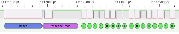
The reset pulse is done by my lead PIC software setting its pin as an output and pulling the pin low. This is done by clearing the relevant bit in TRISIO and GPIO. This needs to be 480us (microseconds) at least. I went with 500us, and measured 534us in PulseView (this will be the overhead of instructions on the slow 4MHz PIC).
The DS18B20 responds pretty quickly after 30us measured, but for safety I check after 70us. I measured the acknowledge response to keep the bus low for 109us, but it can be 60us to 240us. The total time for the presence/acknowledge pulse should be a minimum of 480us, and I went with 500us.
In my other thermometer implementation, I used Timer2 for the long reset routine to minimise delay the impact of delays causing flickering on the multiplexed display, but here since the TM1637 is handling the display I've opted for a simpler implementation and the delays are directly in the routine.
The method oneWireBusReset() does the following:
- Sets GP2 bit on TRISIO to 1, causing the input to float and the bus pulled high by the resistor
- The sets GP2 bit on TRISIO and GPIO to 0, making the pin an output and driving it low (0V)
- Waits 500us - delay_10us(50);
- Sets GP2 bit on TRISIO to 1 again, releasing the bus for the DS18B20
- Waits 70us - delay_10us(7);
- Checks the result of GP2 on GPIO. If it is still high, that means the DS18B20 did not pull the bus low (ACK signal). oneWireIsPresent is set to zero, but I don't do anything with it. It could be used to display Err on the LED segment display though for example
- Wait a further 500us - delay_10us(50);
/*********************************************************************************************
  oneWireBusReset()
  First part of the reset routine - drive the bus low for 500us
*********************************************************************************************/
void oneWireBusReset() {
    char isPresent;
    oneWireTris = 1; // start with high
    isPresent = 0;
    // Send the reset pulse - drive low for 500us
    oneWireBus = 0;
    oneWireTris = 0;
    delay_10us(50);
    // Release line and wait 70us for PD Pulse
    oneWireTris = 1;
    delay_10us(7);
    // Now sample, if there is a sensor on the bus, the line should be low
    if (oneWireBus) {
        oneWireIsPresent = 0; // no devices
    }
    delay_10us(50);
}
After the unique reset pulse, the next set of communication is leader microcontroller writing bytes to the DS18B20.
/*********************************************************************************************
  oneWireTxBytes(char data, char data2)
  Transmits a 2 bytes from the bus
*********************************************************************************************/
void oneWireTxBytes(char cData, char cData2) {
    // Reset first - done in main
    //oneWireBusReset();
    // Send first byte
    oneWireTxByte(cData);
    // Send second byte
    oneWireTxByte(cData2);
}
To write bytes to the DS18B20, the lead microcontroller controls the bus only. It must pull the bus low, and then either release it within 15us to write bit '1', or keep it held low for at least 60us to write bit '0'.
/*********************************************************************************************
  oneWireTxByte(char data)
  Transmits a single byte from the bus
*********************************************************************************************/
void oneWireTxByte(char cData) {
    char cTemp = 1;
    // Loop through the eight bits in the byte
    for (char i = 0; i < 8; i++) {
        // Send the LSB first

        // Drive the line low initially for 3us
        oneWireTris = 0;
        oneWireBus = 0;

        // Delay not needed for 4MHz PIC
        //delay_us(3); // Delay 3us

        if (cData & cTemp) {
            oneWireTris = 1; // Release the bus
        }

        delay_10us(5); // Delay 60us - 50us works fine with code delays
        oneWireTris = 1; // Release the bus

        // move the test bit
        cTemp <<= 1;
    }
}
Since the PIC is running at a slow (but power friendly) 4MHz, for writing '1' the bus is released immediately in code after pulling it low. The 'if' instruction in between pulling the bus low and raising it again is enough to hold the bus low for 6us, and the DS18B20 successfully detects that. In both '1' and '0' bits, the line is either kept low or released for 60us. With the overhead of instructions though the window is 78us before the next bit is sent. That's close to ideal as each write bit time slot should be at least 60us + 1us recovery time.
The bits in each byte are sent from the least significant bit (LSB) first, so in the example above the bits detected as 00110011 should be read as 1100 1100, or 0xCC in HEX. This is the first command, which means Skip Rom - address all devices. The cTemp is a test byte which starts with the LSB set, and the bit is moved to the left each time the loop runs. When doing a logical AND with this test byte and the data byte, the routine knows whether to send '1' or '0' down the bus.
The second bit is 00100010, read as 0100 0100 or 0x44 in HEX. This is the second command, meaning Convert T. The two bytes sent I measured as taking 2ms (milliseconds) in total.
After a delay of 750ms, which is measured by the PIC timer1 instead of blocking the main code execution, the temperature is read.
A reset pulse and then another two bytes are sent from the leader PIC, the same 0xCC command, then the 0xBE command which is the read scratchpad. Then we come on to reading...
Once the DS18B20 receives the 0xBE command, it will prepare itself to send the data out from its SRAM (the scratchpad). Each bit is sent, LSB first again, but the BS18B20 will only send the bit if it detects the leader PIC is ready to receive it. The send this notification, the PIC will drive the bus low, but then release it again. This happens immediately in my code, measuring 4.5us. It only needs to be at least 1us.
Once that happens, the DS18B20 will then either drive the bus low itself or release it. The PIC then checks the status of the bus 6us after releasing it and will read the bit as '1' if the bus is high, or '0' if the bus is low. The bit is shifted into a byte from the right and then the routine is held for 60us to ensure the read time slot is safely passed before starting the next one. The read slot in total only needs to be at least 60us. With all the code together, it measures 92us per bit.
Bits are received from the ds18b20 LSB first. The cDataIn variable initially starts at zero. During each loop execution, the bits are shifted left, and if the ds18b20 is sending a high bit on the bus, the MSB (bit 7) in cDataIn is set. So, if the LSB is sent first, bit 7 (MSB) is set on the first iteration of the loop. The next iteration will move that bit to right each time, so once the loop runs eight times, the MSB is now the LSB, and each subsequent bit is filled in from left to right.
/*********************************************************************************************
  oneWireRxByte()
  Receives a single byte from the bus
*********************************************************************************************/
char oneWireRxByte() {
    char cDataIn = 0;
    // Loop through the eight bits in the byte
    for(char i = 0; i < 8; i++) {
        // Bring bus low for 15us
        oneWireTris = 0;
        oneWireBus = 0;

        // Delay not needed for 4MHz PIC
        //delay_us(15); // Delay 15us

        // Release bus for 6us, this is enough time for the slave to respond
        oneWireTris = 1;
        delay_us(6); // Delay 6us

        // Shift data already received left
        cDataIn >>= 1;
        // Check the value of the onewire bus - set the MSB of cDataIn if so
        if (oneWireBus)
            cDataIn.7 = 1;

        // To finish time slot
        delay_10us(6); // 60us
    }

    return cDataIn;
}
Getting the timings right was tricky. The onewire.h library included in BoostC did not work for me, and nor did various examples online, though I've referenced them below as they certainly helped. Reading the DS18B20 datasheet carefully though provides lots of help.
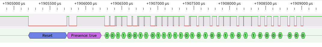
Shown by the pulseview capture, the bits returned are 0110 0010 and 1000 0000. This is LSB, with the low byte coming, so translated its 0000 0001 0100 0110 (1 and 70, or 326). Divided by 16 gives the actual temperature in Celsius - 326/16 = 20.375 degrees.
Translating the temperature
For simplicity, only Celsius is supported for this project, and temperatures over 99 degrees are not supported. I'm unlikely to use it in these temperatures and the components I've used probably have no better than 85 degrees rating anyway.
Negative temperatures are supported though. The left most display will display a minus sign in this case. From -9.99 to 0, two decimal places can be displayed, but for -10 and lower though, only one decimal point is supported.
I came across two great pieces of code from two different places online (see references below and in the code). One will take the ds18b20 reading and convert it to Celsius multiplied by 100. This is quite simply (6 * iTemp) + (iTemp / 4) - and it works perfectly. Because there is multiplication and division there, the assembler generated is pretty large (PIC16 does not have multiply and divide instructions), however it's not much larger than my original method. The division by 4 is simple enough because it is the same as shifting the bits two to the right (and the BoostC compiler detects this).
As an example, if the ds18b20 read 20 Celsius, it would return 320 (0000 0001 0100 0000). (6 * 320) + (320 / 4) gives 2000 (actual temperature times 100). For 20.5, 328 is read, and the result is 2050. If a 20.125 is given, 322, it will return 2012. The decimal place is truncated, so it's not perfect (should be 2013), but good enough.
The Fahrenheit conversion can be performed using a similar piece of math requiring division - ((iTemp + 4) / 8) + iTemp + 320. It's not used here though, see my original PIC thermometer project.
My convertTemp() function uses the Celsius technique above to display the temperature. It does this:
- Takes the upper and lower bytes returned from the ds18b20 and create a signed integer number (iTemp) from them. Assumes the decimal place is in the middle to begin with (2)
- Get an absolute value of iTemp first by applying two's complement logic to the number if it is minus
- Perform the Celsius conversion (6 * iTemp) + (iTemp / 4)
- Split the digits
- Write the converted byte for each segment to tm1637Data, using the tm1637DisplayNumtoSeg array
- If the left-most digit is 0, write 0 to tm1637Data so no segments are displayed
- If the temperature is negative and -10 or lower, shift the digits to the right (this will truncate the second decimal place)
- If the temperature is negative, put a minus sign in the left most digit
Splitting the temperature into four different digits is based on advice found online. This method generates less instructions for the PIC compared to using the divide / and modulus % operators to split the digits up, at a slight cost of execution cycles (due to the loops).
I changed it a little to not need signed numbers, and at the end the digits are left fill a blank, so a temperature of 7 would be displayed as 7.00 instead of 07.00.
The splitting happens four times. The first (thousands) digit is worked out by taking off 1000 from the value whilst it is greater than 1000. So, if 10 was sent, nothing happens and cDig3 remains as zero. If 1000 was sent though, the loop executes once and cDig3 becomes 1.
The process repeats for 100 and 10. The final digit (units) is just whatever is left on iValue.
/*********************************************************************************************
  displayTemp()
  Used to split the 16 bit integer returned from the ds18b20 into parts for display
  cTempH - upper 8 bits
  cTempL - lower 8 bits
*********************************************************************************************/
void convertTemp() {
    // convert both bytes to a 16bit int - e.g., 0000 0001 0100 0110 (1 and 70, gives 326)

    signed int iTemp = (cTempH << 8) | cTempL;

    // Celcius
    char isMinus = (iTemp < 0);
    if (isMinus) {
        iTemp = ~iTemp + 1;
    }
    // this gets celcius * 100 - https://www.phanderson.com/PIC/PICC/sourceboost/ds18b20_1.html
    int iValue = (6 * iTemp) + (iTemp / 4);

    // Split the temperature reading into digits

    // simple way, but more program memory needed for PIC12 or PIC16 (more than 100 words more)
    //char cDig3 = iValue / 1000;
    //char cDig2 = (iValue / 100) % 10;
    //char cDig1 = (iValue / 10) % 10;
    //char cDig0 = iValue % 10;

    // less program memory needed - may be slower executing
    // https://electronics.stackexchange.com/questions/158563/how-to-split-a-floating-point-number-into-individual-digits
    char cDig3 = 0;
    char cDig2 = 0;
    char cDig1 = 0;
    char cDig0 = 0;

    // incrementing variables for each digit

    // determine to thousands digit
    while (iValue >= 1000) {
        iValue = iValue - 1000;
        // each time we take off 1000, the digit is incremented
        cDig3++;
    }

    // determine to hundreds digit
    while (iValue >= 100) {
        iValue = iValue - 100;
        // each time we take off 100, the digit is incremented
        cDig2++;
    }

    // determine to tens digit
    while (iValue >= 10) {
        iValue = iValue - 10;
        // each time we take off 10, the left most digit is incremented
        cDig1++;
    }

    // the last digit is what's left on iValue
    cDig0 = iValue;

    // translate the numbers to digit values
    tm1637Data[0] = tm1637DisplayNumtoSeg[cDig3];
    tm1637Data[1] = tm1637DisplayNumtoSeg[cDig2] + tm1637Dot;
    tm1637Data[2] = tm1637DisplayNumtoSeg[cDig1];
    tm1637Data[3] = tm1637DisplayNumtoSeg[cDig0];

    // left fill zeroes with blanks up to the digit before the decimal place
    if (cDig3 == 0) {
        tm1637Data[0] = 0;
    }

    if (isMinus) {
        // If minus and value less than or equal -10 (checked as >1000), shift the digits right
        if (iValue >= 1000) {
            tm1637Data[1] = tm1637Data[0];
            tm1637Data[2] = tm1637Data[1];
            tm1637Data[3] = tm1637Data[2];
        }
        // If minus, overwrite left most digit with minus sign
        tm1637Data[0] = 0x40;
    }
}
Main loop
The main() method is what is entered as soon as the PIC is powered on. This should call the initialisation code (in the initialise() method), followed by an initial covert and display update (these are for testing purposes) and then enter an endless loop that has a basic task scheduler inside it.
The task scheduler looks for bits being set int he cTask variable, and if any are set, the scheduler will then execute that task.
In this case the two possible tasks are TASK_TIMER1_START and TASK_TIMER1_READ. Both are set by the interrupt() method on the relevant counts of timer 1.
void main() {
    initialise();
    convertTemp();
    tm1637UpdateDisplay();

    // Endless loop
    while(1) {
        // Task scheduler
        // If there are tasks to be performed, find out the
        // most recent task from the array and execute it
        while (cTask > 0) {
            if (cTask.TASK_TIMER1_START) {
                // Timer 1 has finished counting to 30 seconds, ask to convert
                oneWireBusReset();
                startTemp();
                cTask.TASK_TIMER1_START = 0;
            }
            if (cTask.TASK_TIMER1_READ) {
                // Timer 1 has finished counting a further 750ms, read the converted temperature
                oneWireBusReset();
                readTemp();
                // store it in the array, next display refresh will pick it up
                convertTemp();
                // Display on TM1637
                tm1637UpdateDisplay();
                cTask.TASK_TIMER1_READ = 0;
            }
        }
    }
}
Conclusion
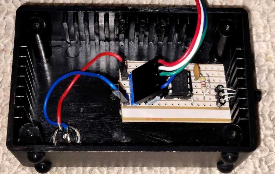 Above: Stripboard PCB mounted inside the project box
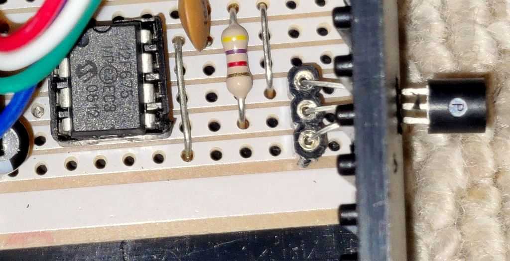
Above: View of how DS18B20 is mounted
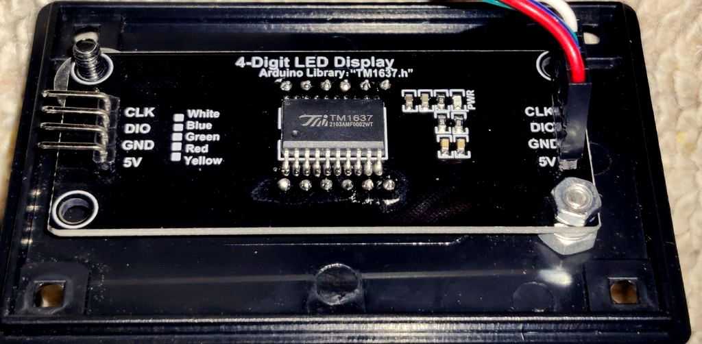
Above: TM1637 module
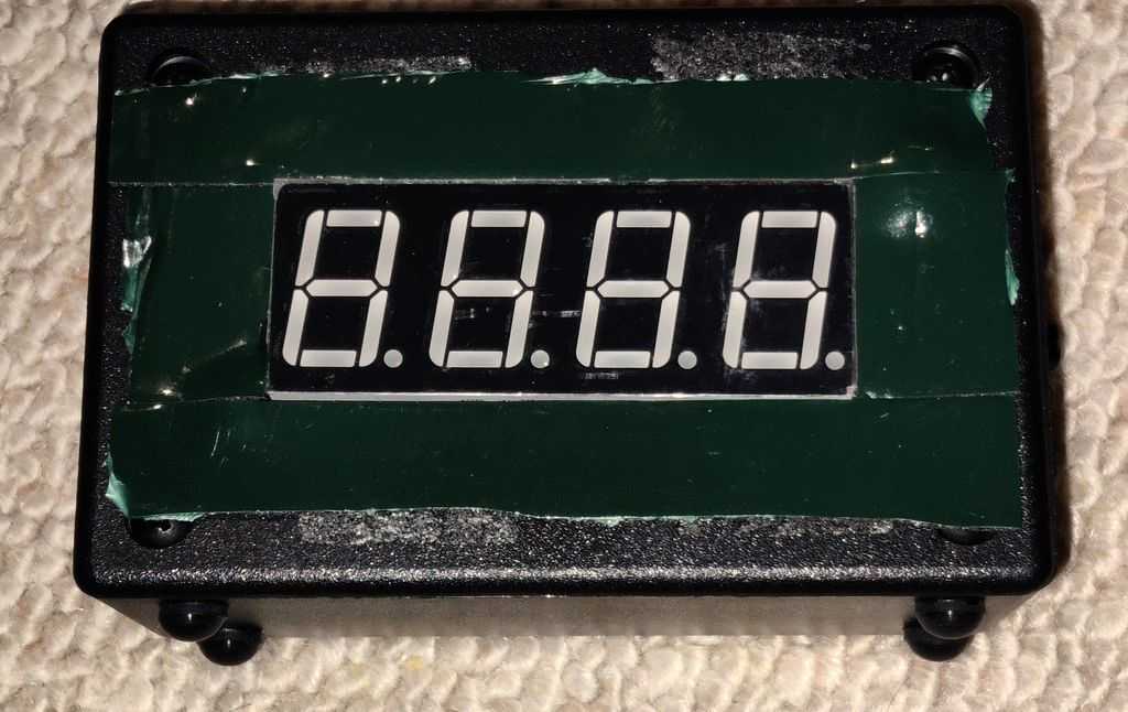
Above: Front view, before sticking the translucent smoky blank plastic in front, via double sided foam tape
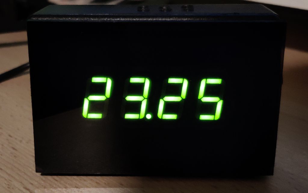
Above: View of module operating
There is a flaw in the design a bit. The TM1637 module actually generates some heat itself. Despite adding some ventilation holes, the temperature read in this thermometer would still read about 0.5 to 1°C higher than my original implementation (mostly around 1°C higher).
This would be resolved by mounting the DS18B20 further away from the display itself, but since I'm unwilling to do that, I 'patched' the code by taking 100 (1°C) away from the converted temperate (iValue) before displaying it. This patch will not work below 1°C though!
That's really all there is to the program. The whole lot uses 599 words of ROM (out of 1024), 51 bytes of RAM (out of 64) and runs successfully from the PICs internal 4MHz oscillator. That code uses most of the resources available on the PIC, so if you are planning a temperature monitor / thermometer with more advanced functions, you will probably need a better PIC with more ROM and RAM.
Thanks to my previous project and experience, the simplicity of the schematic with no need for a custom PCB, this project was really quick, and does what I need it to - displaying the temperature, all day, every day.
References and more reading:
- Source code on github.com
- PIC Thermometer - my previous build
- PIC12F629/675 datasheet
- DS18B20 datasheet
- TM1637 datasheet
- SourceBoost Technologies - low cost, high performance cross compilers
- UsbPicProg - Open Source Microchip PIC programmer
- GitHub - Arduino library for TM1637 (LED Driver)
- Dring Engineering Services - IC Timer Calculator and Source Code Generator
- Technicalfeline - A comparison of the TM1637 protocol with I2C protocol
- SourceBoost Forums - DS18B20 one wire reference for SourceBoost
- Peter H. Anderson - DS18B20 SourceBoost implementation, including ds18b20 to Celsius x100
- Electro-Tech-Online - Temperature Sensor DS18B20 Display Fahrenheit, ds18b20 reading to Fahrenheit x10
- Electro-Tech-Online - PIC Single-Chip 4-Digit DS18x20 Temperature Monitor
- Circuit Digest - Digital Thermometer using a PIC Microcontroller and DS18B20