
PIC Microchip Delay/Boost Timers
Source code is available on github.com.
Here's a small project that helped me with a specific problem and could be useful wherever a simple delay based timer is required.
Typical winters' morning - wake up, straight to the bathroom, wash and dry yourself with a towel. Our bathroom is only ventilated with an extractor fan though and the damp towel tends to take on an aroma! The towel rack is heated, so remembering to switch that on before showing and back off once all bathroom chores are complete helps evaporate the dampness off the towel.
In the mornings though, the brain typically isn't running properly though, and sometimes we'd forget to turn off the towel rack heater and it may be left on for hours before we realise. That doesn't help the electric bill (especially true since late 2021), or planet Earth!
Recommended Experience : Intermediate, knowledge of programming, microprocessor programmer, custom PCB used, optional mains voltages
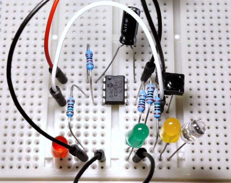
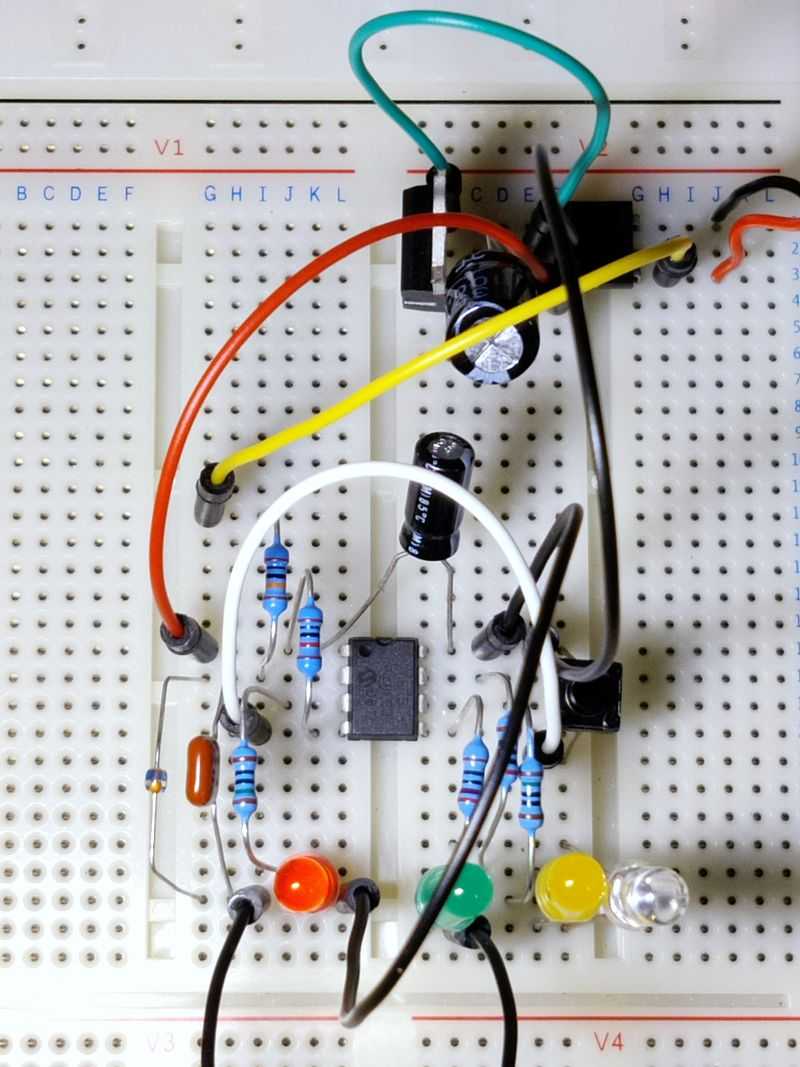
Above: View of timer on breadboard
At the end of 2017, I thought to myself I must have enough spare/salvaged components to build a simple timer where a button is pushed, and this would switch on the electricity to an appliance (mentioned heated towel rack) and then automatically turn it back off after a pre-determined time.
The idea would work very much like a 'boost' timer for immersion water heaters which would give the upper section of a water tank 2kW of heating for either 30 minutes, 1 hour or 2 hours, depending on how many times you push the boost button.
A simple timer like this simple to achieve with a microcontroller, and I always make sure I've spare ones.
Hardware
The hardware was going to be coming from my parts collection, so I didn't have to order anything at all and proceed immediately with the project.
The microcontroller was originally a PIC16F627A, but this is over-the-top for the job and the details below are for a PIC12F675.
Sure, you could build a simple project like this out of discrete components (the 555 timer comes to mind), but it gets tricky with things like switch de-bouncing and having the three user selectable delay options.
A microcontroller makes it all smaller and easier. I always choose a PIC since I'm familiar with them and having the SourceBoost compiler makes writing and reading the code easy, though if you wanted to learn assembler language for any project, a simple one like this would be a good place to start.
Around the microcontroller, some other hardware is needed:
- A Relay, switched with a transistor, resistor and diode - this is what is used to switch on/off the appliance. Having an electromechanical relay means whatever voltage we're switching is isolated from our timer. This means the switched voltage can be any DC or AC voltage within the relays rating.
- A Push-to-make Button non-latching / momentary, pulled up with a resistor - this is the user input. To keep it simple, only one button is required
- LEDs with current limiting resistors - in my build I selected three LEDs to indicate how long the timer was set for
- Power supply - for the PIC microcontroller and relay coil (NOT the appliance). This would be 5V typically.
The hardware is very minimal as most of the work would be done in software on the microprocessor.
Relay
Electromechanical relays feel a bit old fashioned (an early 19th century invention), but they are one of the more fascinating components and are extremely useful. I would say I've built about 30 to 40 different small and large projects involving relays.
The choice of relay is important, really important though! Relays have several ratings:
- The voltage they can switch
- The current they can switch
- The voltage of the coil
- The resistance of the coil
I'm only going to consider electromechanical relays in my advice. I've never used and don't really have the desire to use solid-state relays due to the additional complexity. Rod Eliott (ESP) has a great article on them for further reading though (linked below).
Relay Contacts
The first two are related to the appliance. You need to ask yourself what it is, what voltage (V) it requires and what current (A) it draws.
Before we cover the ratings - check the contacts type first. Is the relay SPST (single pole single throw)? If it is, check whether it is NO or NC (Normally Open or Normally Closed). We'll want to use Normally Open contacts so the appliance being switched is off until the relay is activated.
Next, we need to consider how many poles there are. A single pole relay is basically a single switch, but a double pole relay is two switches that are electrically separate, but they activate at the same time when the relay is energised.
If it's low voltage DC, such as switching a few LED lights or a 12V computer fan, things like that, many common relays will be OK, but I suggest getting relays rated to switch 30V DC at 1A minimum. Note that if the relay can switch 30V at 1A DC that does not mean it can switch 15V at 2A. It's still 1A! Check what you need it to switch and go for a rating higher than this.
In my case my appliance was a heated towel rack. This is powered directly by mains electricity, so in the UK that's 250V AC. It's rated for 400W (so that's 1.6A) and is fused with a 3A standard UK fuse in a switched spur (outside the bathroom).
IF YOUR SWITCHING MAINS ELECTRICITY, DEATH OR SERIOUS INJURY MAY RESULT. YOU SHOULD NOT ATTEMPT TO DO THIS UNLESS YOU ARE CONFIDENT AND LEGALLY QUALIFIED.
Even if you are switching DC, high DC voltage may also be deadly. Any error either immediately, or eventually, due to mistakes and you could be either liable for loss of life.
If your relay must switch mains AC, check the voltage is sufficient. There's plenty of 125VAC relays but if you need to switch 250V AC you must check the rated current. Often it will be half the 125VAC current, but if the datasheet does not specify 250VAC, do not use that relay because it is unrated to do so (therefore unsafe) and will prematurely fail.
The current rating should be more than the current draw of the appliance and could be many times more! Heaters and light bulbs are typically resistive, meaning their initial power draw is the same as their typically operating power draw. Other devices though may be inductive (i.e., anything with a transformer, motor, solenoid, electromagnet, or other relay coils) or capacitive (power supplies, long cables) and they will surge when switched on.
The surge will be more than the rated current marked on the appliance. If you don't know the inrush current of an inductive load, measure it if you can (needs an advanced multimeter), or go with 30 times the typical current (or a combination of 30x switched current and voltage).
So, a 250W 250VAC motor absolutely cannot be switched with a 1A relay. It'll probably destroy the relay on the first attempt! It needs a 30A relay to give reliable operation. These are expensive though, and you may want to look at techniques of limiting the inrush current, zero voltage crossover detection, spark reducing capacitors to control this surge power. All that is beyond the scope of this article.
My heated towel rack is a resistive load, but I went for a commonly available relay rated for 10A at 250VAC. Five years later it still hasn't failed.
Another important point, you may also need to use a double pole relay. In countries where the mains voltage consists of a live and neutral wire, it's safe to switch only the live wire with a single pole relay.
But you have to be certain that you are always switching the live wire as switching the neutral only is not safe. Bear in mind that if you switch follows a plug/socket that is reversible (i.e., US, Japan and some European ones), or the input to your switch is a figure of eight (IEC C8) - you cannot guarantee what wire is live and you should instead use a Double Pole (DPST or DPDT) relay so that both lines are switched.
Finally, if there is a safety earth wire (and hopefully there is), never switch this with your relay. Always leave it connected as it's there for safety and should never be disconnected by any means.
Relay Coil
The other part of the relay we need to think about is the coil. These days, 5V relays are more common, but they are still outnumbered by relays with 12V coils. Relays with high contact ratings typically need higher coil voltages too so they can reliably pull the switch arm onto the coil magnet.
Microcontrollers such as the PIC family usually support running off 5V. So, picking a relay with a 5V coil makes some sense as we can use the same power supply. A transistor is still needed to switch the relay in this case, but more on that later.
If you're building a timer which isn't switching mains voltage and it's using an external DC adaptor like a 5V wall-wart, using a 5V coil relay is the best choice.
Alternatively, if you are switching mains and building a power supply for the PIC, you can pick a transformer with 9V AC secondary coils.
When rectified, this gives about 12V DC anyway, although unregulated. The vast majority of 12V relay coils happily operate on unregulated voltages. My relay for example has a pull-in voltage of 75% (so 9V) and a max allowable voltage of 110% (13.2V). 9V AC rectified via a cheap bridge rectifier will be within this voltage range.
The other thing to consider is the coil resistance. This together with the voltage gives the (typical) coil power consumption. My relay is 320 ohms, so at exactly 12V that's a current of 37.5mA, power of 0.45W.
It's quite modern, hence the low current draw but some relays will draw considerably more power. If the coil has a resistance of 100 ohms, that's 0.12A (120mA), and a power consumption of 1.44W.
As coils are inductive, the inrush will be higher.
They will also emit back EMF (electromotive force) when released.
There's three points here I'm trying to make:
- Your microcontroller will not be able to drive the relay directly. Even if the pin can output 5V, it cannot source more than a few mA and will not cope with the inrush current of the relay. You will need a transistor or MOSFET to switch the relay.
- The back EMF can still destroy a transistor or the microcontroller behind it, but that can be solved by adding a protection diode
- The typical power consumption of the coil needs to be factored into the power supply design. Many small transformers may only be able to provide 100mA or rated at 0.45VA for small PCB transformers. These won't be big enough to power a 0.45W relay and a microcontroller.
The type of transistor is an NPN transistor. Many small signal transistors would easily be capable of doing the job. I used an old 2SC1815 because I have lots of them, but a more common choice would be a BC549 or 2N2222. Know the relay coil voltage and resistance to work out the current the relay draws, and then ensure your transistor has a collector current rating higher than this.
For picking the base current limiting resistor, you can use R = ((V - 0.6) × Hfe) / I, where I is the relay current, and V is the base trigger voltage and Hfe is the transistor forward current gain. So, for my relay, that's ((5-0.6) × 100) / 0.0375 = 11733. A resistor value lower than this will be fine, so 10k will work but I usually go with a standard 1k resistor when working with low trigger voltages anyway as the current drawn on the microcontroller is still easily within limits and ensures that transistor goes into hard saturation (a Hfe of 10 is typically picked).
Push-to-make Button
The choice of this is much easier! This button/switch is only connected to the input pin of the microcontroller and therefore only needs to handle 5V DC at a very small current.
It's not a power switch, so don't get a latching one. Non-latching or momentary switches make ideal push buttons. We only need SPST (single pole, single throw) though SPDT/DPDT or other changeover switches may be used if you wire the appropriate two terminals.
My choice was also for an IP rated switch, so it can be pushed with damp hands.
The switch should go between the microcontrollers input pin and ground. A pull up resistor of around 10k should be used between the input pin and VSS (e.g., +5V). This will mean the microcontroller reads a high signal when the switched is in its normal position (not pushed). When the switch is pressed, it shorts the pin to ground, and the microcontroller will read a low signal.
Note: The resistor could be excluded if we enabled WPU Weak Pull Ups on the PIC. Most PIC microcontroller have this option on some input pins only. On the PIC12F675, for example, every pin allows it except GP3. For compatibility and understanding though, my schematics show a pull up resistor.
LEDs
Like the boost timers for immersion heaters, three LEDs can be used to indicate how much time the timer has been set to. I picked some old LEDs - one green, one yellow and one red.
The LEDs need appropriate current limiting resistors and there are plenty of calculators online for giving a correct resistor for a known LED forward voltage. The input voltage from the microcontroller will be 5V. I used 150 ohms for my standard LEDs. This will be suitable for many standard LEDs but if you know the forward current, and voltage drop you can calculate the resistor you need exactly.
Power supply options
You've two options for the power supply - use an external one or roll your own from the mains power.
External power supply
This is the simple and safe option. Just buy an external power supply from a reputable retailer that will output 5V and at least 100mA (higher is no problem). You may have spare ones already that can be reused.
In your project, you can get a DC 2.1mm or 2.5mm socket which most power supplies come with, or alternatively use a USB socket. Check the polarity of the socket on the power supply - commonly the centre pin is positive, and the outer barrel is negative but sometimes it is the reverse so check that first.
If you use an external 5V PSU, you'll need a relay coil that is 5V too.
Mains power supply
If you're switching a mains powered appliance, you'll be doing the mains wiring anyway so you could take the input AC and feed it to a transformer.
PCB transformer of around 2.5VA or more are fairly cheap, small and easy to mount on a custom made PCB (but NOT stripboard!). Alternatively, small chassis transformers are an option.
My suggestion is to get one with 9V AC secondary outputs. This provides plenty of input voltage for a bridge rectifier followed by a 5V linear regulator and has a secondary benefit of providing around 11V to 13V unregulated DC which can be used to trigger a relay with a 12V coil.
Following the transformer would be a bridge rectifier, which can either be four diodes (1N4001 or better) or many small bridge rectifier packages exist either in DIP form or others.
When rectified, 9V AC will give around 11V to 13V DC. It gets lower depending on how much power is drawn. This is OK for a 12V relay, but for the microcontroller we need to regulate it and 5V is a typical voltage for microcontrollers.
A regulator will output a stable 5V voltage no matter how much the load varies within its limits. The old fashioned 7805 (or 78L05) are perfect for the job. They do burn the voltage difference (around 6 to 8V) as heat, but our microcontroller requires only 3mA of power at 5V in the worst case. The LEDs should draw no more than 20mA each (with 150 ohm resistor), so we can say 70mA in total needed, representing around 490mW of heat.
Most of the time when the timer is off the microcontroller can sleep too, and LEDs off, needing only less than 3µA of current! That's why I recommend a linear regulator because of its simplicity and with the current draw being so low most of the time switching regulators could actually be less efficient at such low power.
Note: 'Transformerless' power supplies are also possible, but I strongly advise against them. Using one makes your whole circuit (including the push switch and LEDs) at mains potential and all need to be double insulated. They are also limited in how much current they can supply and even switching one relay requires too much. Once you factor in the cost of the components it's unlikely to be cheaper than a small transformer, rectifier and linear regulator anyway.
Mains timer
One advantage of tapping into the mains with a transformer to power our timer is we can also use the mains cycles to increment our timer.
Mains voltage is either 50Hz or 60Hz AC, depending on what country you're in. That means the voltage will alternate in a sine-wave from positive to negative and back to positive again 50 or 60 times a second.
When the transformer converts this into 9V AC, it's still at 50 or 60Hz AC, but now that AC voltage is much lower and safely isolated from the mains by the magic of magnetism.
A few components may be used to allow the AC voltage to be connected to the microcontroller clock/timer input pin. In software the timer would then start counting those pulses and we can count 1 second once the number of pulses reaches 50 or 60.
Doing this is a little more accurate in counting seconds then internal oscillators. External watch crystals are a more accurate alternative for short periods, but I didn't have one.
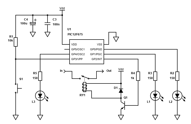
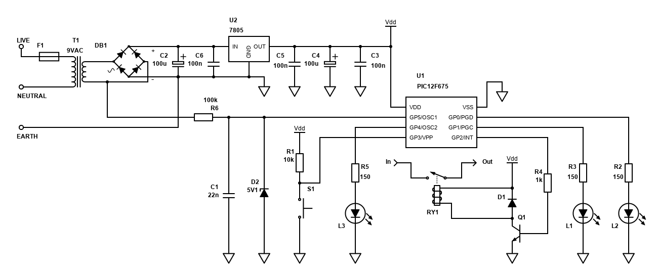
Circuit/Schematics
With that, I'll present some versions.
The first two versions and the last are all simple versions powered off a 5V external DC adaptor and assume a 5V relay coil. They may be built on breadboard or Stripboard/Veroboard, but many relay types are unlikely to fit on Stripboard, so you may want to build your own PCB for it or buy a separate 5V relay board module. This is especially important if you're intending to switch mains as mains voltage through a Stripboard is NOT safe as it does not provide the required isolation gaps needed (should be >1.5mm) and the track widths are not wide enough to carry high current.
For simplicity, small size and low cost, a PIC12F675 is used in all circuits, but other PICs can be used. This is only an 8 pin device, which means after +/- power connections, 6 I/O connections are possible, with one of them being input only (GP3) so that's where the switch is connected.
I've tried several configurations:
- Timer based on the internal oscillator - not accurate, but simple to build and can be adjusted by altering the program. This version allows use of all 6 pins.
- Timer based on an external crystal (e.g., 4MHz) driving the clock. Much more accurate, but the crystal occupies two pins leaving just 4 pins for components, so only two timer settings are possible on the PIC12F675 (a larger PIC with more I/O pins would fix this issue though).
- Timer based on monitoring the mains AC frequency (50Hz or 60Hz) - accurate and quite simple. Uses only 1 pin for the AC frequency input therefore three timers are supported.
- Timer based on DS3231SN RTC
Versions one, two and five are low power, so could be battery operated, but any 5V PSU or USB power would also work fine. The third is AC driven and will require access to an AC PSU to monitor the frequency.
PIC12F675 intro
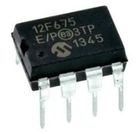
The PIC12F675 is a cheap microcontroller that's available in a small eight pin DIP package (or even smaller SOIC or DFN-S). It's cheaper than a cup of tea, but it's more versatile and capable than many other components.
It's a RISC CPU at its heart. This is 'proper' RISC with only 35 possible instructions. Its specifications are low - only containing 1024 words of flash program memory, 64 bytes of RAM and you would typically run it at 4MHz, though with an external crystal it can run at up to 20MHz.
This sounds useless compared to many devices today (PCs, phones, TVs etc) but for a simple timer it's actually a nice specification. Remember that it will contain only a very simple program, no operating system etc.
Being an 8-pin device means the input/output capability is limited. Two pins are obviously needed for power (i.e., +5V for VDD, 0V for VSS), but the remaining 6 pins can be used for inputs and outputs. The pins are referred to as GPIO (which is unlike other PICs that normally have port A, port B etc).
It supports voltages from 2V (with ADC off and speed <= 4MHz) to 5.5V. You'll need 4.5V if you intend to run it at speeds above 4Mhz. I'll run it at 5V in all my tests anyway because 5V power supplies / 7085 regulators and 5V relay coils are far more common.
We'll be using some features of this microcontroller common to all these circuit options, those being:
- Sleep - when the timer is idle (doing nothing), the microcontroller will sleep to save power
- Interrupt-on-change - this is so that the push button switch will wake up the PIC and an interrupt routine will fire, which we can process actions from programmatically.
- Timer 0 - this will be used to debounce the push button switch. It'll get enabled on the first interrupt-on-change and once the timer interrupts the switch will be checked if it is still pressed. In some versions, Timer 0 is also used to drive the delay timer itself (using Bresenham's Algorithm)
- Timer 1 - this will be running the timer for the mains and DS3231 options.
There are few things to note and watch out for:
- GP3 is an input only pin and cannot be used as an output. It also does not have internal weak pull up (open drain only), so an external resistor is needed.
- Any pins configured as an input may need the ADC and/or comparator disabled
- The CONFIG word - this should have MCLRE OFF (so GP3 can be used as an input), PWRTE ON (gives enough time for PSU to stabilise), WDT OFF (so watchdog timer does not reset the PIC) and FOSC set to INTOSC oscillator (I/O function on GP4/OSC2/CLKOUT and GP5/OSC1/CLKIN pins)
- T1OSCEN should be set to OFF so we can use the GP4 pin for I/O, except for version 2 where we need to drive the crystal
The microchip will need to be programmed. I use SourceBoost with the BoostC compiler to write the code and compile/assemble it down to PIC compatible hex code.
I then use the UsbPicProg - Open Source Microchip PIC programmer to burn that hex code onto the chip itself. The programmer board I built and etched myself thanks to the instructions provided at the UsbPicProg website and it works well. An ICSP header on the programmer is then used to a small adaptor I built on stripboard for the 8-pin PIC12F675 chip.
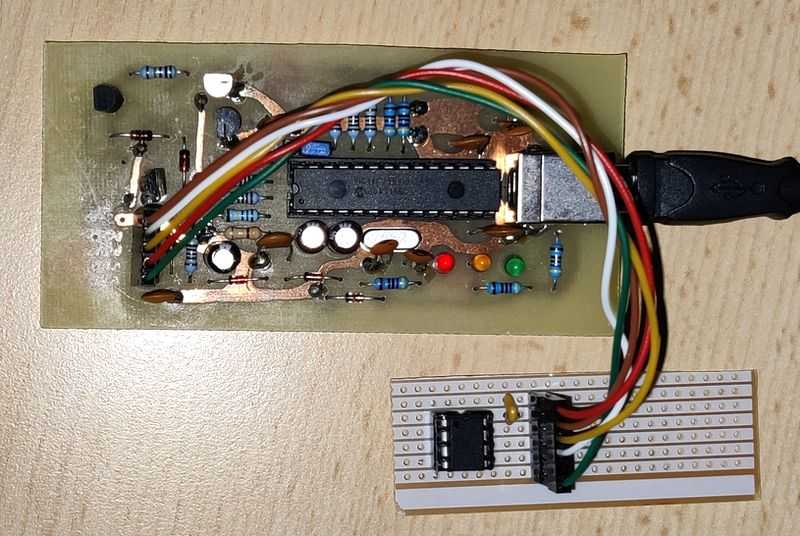
You could also build the ICSP header directly on your final implementation if you leave the VPP, PGC and PGD pins free, or follow advise on isolating the from the rest of the circuit if you want to use them as I/O (this is tricky though).
With my work using the PIC12F675 so far though, to program it, I just lift it out of the breadboard or DIP socket and place it in the programming adaptor to burn the new program on it. Then lift and shift it back to the application circuit for testing.
WARNING the PIC12F675 comes with a factory calibrated oscillator adjustment which is stored in the program code memory at location 3FF. This value is then copied to OSCCON at start up, but some programmers may erase this value. UsbPicProg I use seems safe but do a read first and check the last two bytes which should be 34 followed by value, in my case below, 34 50 (UsbPicProg displays them reversed).
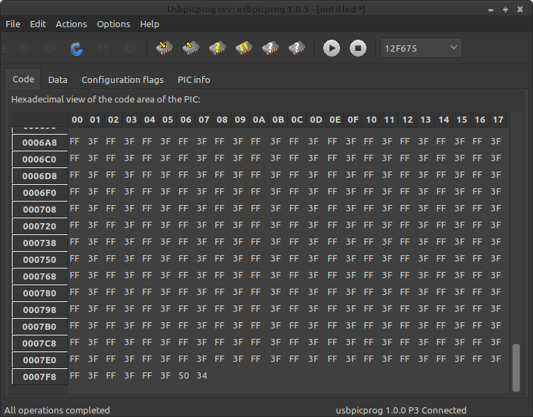
If your factory calibrated oscillator setting is erased (reads 3FFF) - see Internal Oscillator Recalibration Utility at Picprojects. The program will crash in the asm block of code below if the value is erased. If the asm block is ignored, the internal oscillator will run but with a significant variation to the 4MHz speed expected.
From reading, the calibrated value is best for running at 3.3V rather than the 5V I run the timer at. It will still give reasonable results on 5V though and you can use the calibration circuit and code linked above to get a better value.
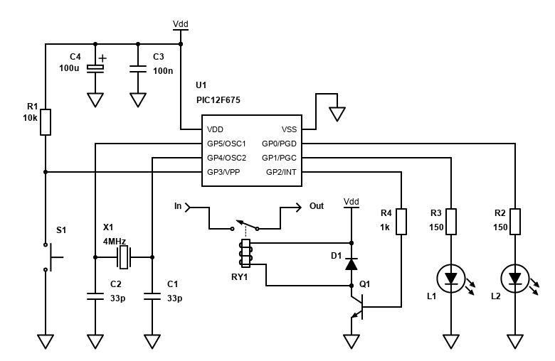
Simple/internal timer
This is the simplest version, requiring just the PIC, two capacitors, five resistors, three LEDs, a transistor, diode, relay and a tactile switch (push button).
I've written the program with three timers - one 10 minutes, another 20 minutes and the final one at 30 minutes. How it works is simple - press the button once and the relay and LED-1 will pulse for 10 minutes, then deactivate again.
Press the button a second time, and now the timer will be for 20 minutes. LED-2 will pulse for 10 minutes, then it will be switched off and LED-1 will pulse instead for a further 10 minutes. When the full 20 minutes has passed, both LEDs are off, and the relay deactivated.
Press the button a third time will set the timer for 30 minutes. That's LED-3 for 10 minutes, then LED-2 for 10 minutes, then LED-1 will pulse for the final 10 minutes. When the full 30 minutes has passed, all LEDs are off, and the relay deactivated.
Pressing the button a fourth time will deactivate the timer - all LEDs off, and the relay deactivated.
To ensure the circuit is wasting as little power as possible, when the timers are not running, the PIC is put to sleep. This essentially tells the microprocessor to not execute code until an interrupt event occurs to wake it back up again.
The push button will use the interrupt-on-change feature so that it can wake the PIC up from sleep for this reason. When the timers are running, the PIC needs to be awake and executing in order to continuously monitor the elapsed time and perform the relevant action once its passed. Even so, the PIC operates off the 4MHz internal oscillator for this 10, 20 minute or 30 minute time and at 4MHz, the current consumption is still very low.
This timer reduces complexity, cost and size, but since the timer must now rely on the internal 4MHz oscillator, its accuracy will not be perfect.
That's OK though if your timer doesn't really care if it activates for (say) 10 minutes and 6 seconds instead of exactly 10 minutes. In many applications (including my heated towel rack) that sort of accuracy is actually fine as the additional 6 seconds will unlikely make any real world difference.
The timer will use the factory calibrated setting which is within 1%. This could mean the timer is up to 0.6 seconds off counting to 1 minute. Timers based off the internal oscillator will be dependent on the room temperature too, so it'll never be perfect, but again for many applications - it's probably good enough!
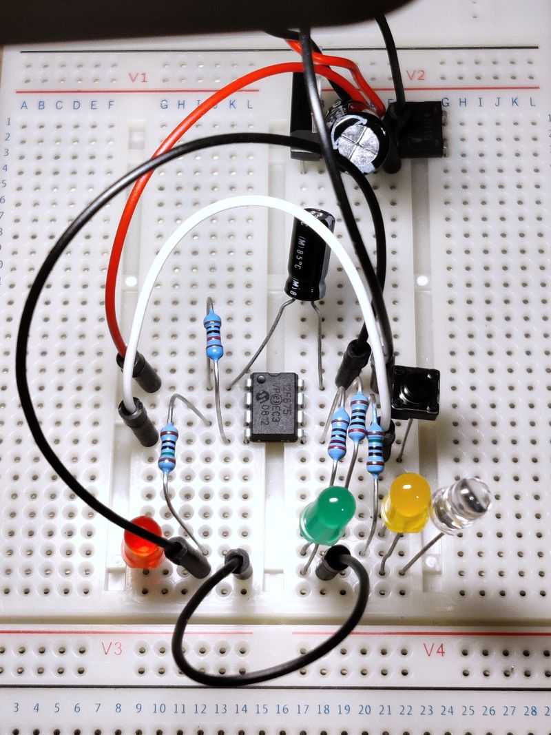
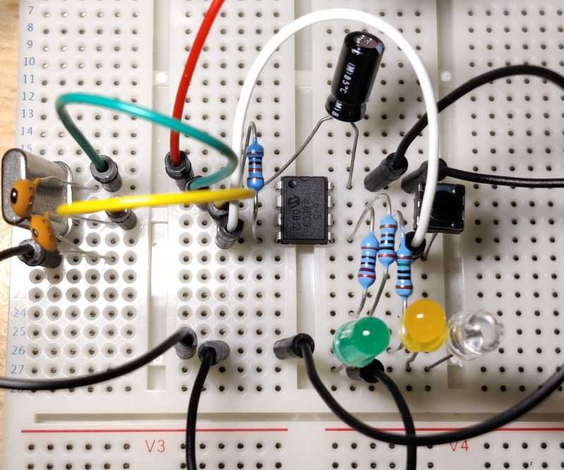
Above: The simple timer on a breadboard. I used a blue LED (the one in the clear package on the right) instead of a relay for
testing. The tactile push button is above this (middle right). I used a 7805 regulator to give 5V as I had a 12V DC PSU handy and I
knew I'd need to build the regulator for the AC driven timer below.
The code for this timer is simple and uses only timer 0 and the Bresenham's Algorithm technique described at https://www.romanblack.com/one_sec.htm.
I've tested the same by using timer 0 to generate interrupts and tick 1 second intervals by carrying over the errors each time. The result is a fairly accurate timer, from a factory calibrated PIC. It still was about 6 seconds longer to 10 minutes than it should be. That's about 1% out, so it might be worth calibrating the oscillator yourself, or you can tweak the 62500 (1000000/16) interval up/down to trim the timer manually - in this case bring 62500 down by 625 (1%) to 61875 helped bring the accuracy to within 1 second in 10 minutes.
This code uses 237 words out of 1024 ROM (less than a quarter of what's available) and 13 bytes out of 64 bytes of RAM and only uses one timer, freeing up the other timers and memory for other creative expansions. You could perhaps use even less words if written directly in PIC assembler.
A little description on how it works...
- The .h file contains some macros which refer to registers and pins, as well as the global variables (that will be stored in RAM)
- The #CONFIG at the top contains configuration word parameters. These are written to the PIC at program time. I have these configured
to:
- _PWRTE_ON - Power-up Timer is enabled. This helps solve start up issues when the power is first applied.
- _WDT_OFF - Watchdog Timer is disabled. I tend to always do this otherwise long intentional delays cause the watchdog timer to reset the PIC.
- _INTRC_OSC_NOCLKOUT - Internal 4MHz oscillator is used to drive the microcontroller's clock, with GP4 and GP5 usable as I/O
- _CPD_OFF - Data Code Protection disabled
- _CP_OFF - Code Protection disabled. You only want to enable it for a commercial product to prevent reverse engineering
- _MCLRE_OFF - allows the GP3 pin to be used as an input
- _BODEN_ON - Brown-out detection enabled (resets the PIC when the power is low)
- On power on, the PIC will enter the main() function at the bottom. This calls the initialise() function, which will
- The asm block is used to read the factory calibrated oscillator setting and apply it to OSCCAL. This ensures the internal oscillator will run within 1% of 4Mhz.
- Set the direction and state of the GPIO pins. TRISIO sets the direction input or output, GPIO sets the state on or off
- Disables the ADC and comparator modules by setting ANSEL to 0 and CMCON to 7
- Sets the OPTION_REG, disabling weak pull ups and setting up the Timer 0 options and prescaler (Timer 0 is used for switch debouncing and counting the seconds in the main delay timer)
- Sets the GPIO on change interrupt, so the switch can wake the PIC when someone presses it
- Initialises the variables
- Enables the interrupts
- The main() function then goes into a loop, and executes tasks based on bits set in the cTask variable. If there is no task and the timers are both off, the PIC goes to sleep (by calling the sleep() function).
- Tasks are flagged by the interrupt() function. This is called whenever there is a hardware interrupt. The hardware interrupts we
enabled in the initialise() method are:
- Interrupt-on-change - GP3 only as only the GP3 bit in the IOC register was set. GP3 is attached to the push switch. Once this interrupt occurs, it is prevented from occurring again by clearing GPIE in the INTCON register. The GPIF bit is also cleared, as you always need to clear the interrupt flag in the routine otherwise the interrupt can never be generated again.
- Timer 0 - will interrupt after the T0IE bit in INTCON register is set (this is done in the main() function once the TASK_INT_IOC
is set). The Timer 0 interrupt has two functions:
- Tick 1 second intervals using Bresenham's Algorithm. Seconds/Minutes are only incremented if the timer is on.
- If the debounce counter is less than 10, it ticks a debounce counter (for debouncing the input button to avoid a single press registering multiple events). >
- The tasks are processed in the main() method. This is to avoid blocking functions in the interrupt() routine that would prevent
further interrupts from being processed.
- TASK_INT_IOC - this is flag once the button state changes - i.e., someone touched it. Timer 0 is reset, and its interrupt enabled at this point
- TASK_TIMER0_DEBOUNCE - happens once timer 0 ticks 200 times (approximately 50ms). A check is made to see if the button is still pushed down on the first interrupt, and if so, the timer presets are cycled through and applied, the correct LED switched on, the RELAY switched on. If after two interrupts the button is released, the interrupt-on-change is enabled again so subsequent button pushes will be registered.
- TASK_TIMER0_SEC - occurs every second if the timer is set. This checks how many minutes have elapsed and toggles the appropriate LED or turns them all off as well as the relay and the timer 0 interrupt setting once the timer has been exceeded.
PIC12FTimer1.h
#ifndef _PIC12FTimer1_H_
#define _PIC12FTimer1_H_

#define TASK_INT_IOC 0
#define TASK_TIMER0_SEC 1
#define TASK_TIMER0_DEBOUNCE 2
#define RELAY (gpio.2)
#define BUTTON (gpio.3)
#define RED (gpio.4)
#define YELLOW (gpio.0)
#define GREEN (gpio.1)
#define TIME1 10  // First push timer - 10 minutes
#define TIME2 20  // Second push timer - 30 minutes
#define TIME3 30  // Third push timer - 45 minutes

char iSec;
char iMin;
char iSetTime;
char cTask;
char iDebounceCounter;
char iDebounceTicks;

unsigned int bres = 0;

#endif //_PIC12FTimer1_H_
PIC12FTimer1.c
#include <system.h>
#include "PIC12FTimer1.h"

//Target PIC12F675 configuration word
#pragma DATA _CONFIG, _PWRTE_ON & _WDT_OFF & _XT_OSC & _CPD_OFF & _CP_OFF & _MCLRE_OFF & _BODEN_ON

//Set clock frequency
#pragma CLOCK_FREQ	4000000

void interrupt() {
    // Handle interrupt-on-change - button press
    if (intcon.GPIF && intcon.GPIE) {
        // Debounce - start timer0
        cTask.TASK_INT_IOC = 1;
        // read gpio
        char readgpio = gpio;
        intcon.GPIF = 0; // Clear interrupt flag
        intcon.GPIE = 0; // Disable interrupt (for de-bouncing)
    }

    // Handle timer0 interrupt
    if(intcon.T0IF && intcon.T0IE) {
        // uses 1 variable; unsigned 16 bit int bres
        // gets here every TMR0 int (every 256 ticks)
        // Count 1 second intervals
        bres += 16;	// add (256/16) ticks to bresenham total
        if (bres >= 62500) { // if reached 1 second (1000000/16)
            bres -= 62500; // subtract 1 second, retain error
            if (iSetTime) {
                // Tick 1 second
                iSec++;
                if (iSec == 60) {
                    // Tick minutes
                    iMin++;
                    iSec = 0;
                }
                cTask.TASK_TIMER0_SEC = 1;
            }
        }
        // Tick the debouce counter, if debounce counter less than 10x (500ms)
        if (iDebounceCounter < 10) {
            iDebounceTicks++;
            if (iDebounceTicks == 200) { // 200 ticks is roughly 50ms
                iDebounceCounter++;
                iDebounceTicks = 0;
                cTask.TASK_TIMER0_DEBOUNCE = 1;
            }
        }
        intcon.T0IF = 0; // Clear interrupt flag
    }
}

void initialise() {

    // Use oscillator callibration value by copying it to OSCCAL
    asm {
        call 0x3FF
        bsf _status, RP0
        movwf _osccal
        bcf _status, RP0
    }
    // GP0 = OUT: LED1
    // GP1 = OUT: LED2
    // GP2 = OUT: Relay trigger
    // GP3 = IN: push button
    // GP4 = OUT: LED3 or OSC2: 32kHz crystal
    // GP5 = N/A, T1 in or OSC1: 32kHz crystal
    trisio = 0b00001000;
    gpio = 0b00001000; // all LEDs/outputs off by default

    ansel = 0; // configure A/D inputs as digital I/O
    cmcon = 7; // compartor off

    // OPTION register - for TMR0 and Weak pull-ups config
    // set the prescaler to the WDT
    // Therefore, timer0 has NO prescaler and will overflow every 256 instructions
    // Bit 7 NOT_GPPU = 1 : disable pull ups
    // Bit 5 T0CS = 0: TMR0 Clock Source Select bit...0 = Internal Clock (CLKO) 1 = Transition on T0CKI pin
    // Bit 4 T0SE = 0: TMR0 Source Edge Select bit 0 = low/high 1 = high/low
    // Bit 3 PSA = 1: Prescaler Assignment bit...0 = Prescaler is assigned to watchdog timer WDT
    // Bits 2-0 PS2:PS0 = 000: Prescaler Rate Select bits, 000 = 1:1 prescaler
    option_reg = 0b10001000;

    // Setup for GP3 Interrupt [Button press]
    ioc.IOC3 = 1; // GP3 interrupt on change
    intcon.GPIE = 1; // GP3/RB0 Interrupt enabled (for button)

    // No task at initialisation
    cTask = 0;
    iDebounceCounter = 0;
    iDebounceTicks = 0;
    iSetTime = 0;
    iSec = 0;
    iMin = 0;

    // Enable interrupts
    intcon.GIE = 1;
    intcon.PEIE = 1;
}


void main() {
    initialise();

    // Endless loop
    while(1) {
        if (cTask.TASK_INT_IOC) {
            // Interrupt-on-change occured - start timer 0
            // Reset timer 0
            tmr0 = 0;
            iDebounceCounter = 0;
            iDebounceTicks = 0;
            // Enable timer 0 interrupt
            intcon.T0IE = 1;
            cTask.TASK_INT_IOC = 0;
        } else if (cTask.TASK_TIMER0_DEBOUNCE) {
            // Timer 0 counted 50ms
            // if debounce counter is 1, check state is still on
            if ((iDebounceCounter == 1) && (!BUTTON)) {
                // Button still pressed and debounced, set a timer
                if (iSetTime == 0) {
                    // This is the first timer, so reset seconds/minutes
                    iSec = 0;
                    iMin = 0;
                    // Also reset tmr0 and bresenham total
                    tmr0 = 0;
                    bres = 0;
                    // Set the timer to the first option
                    iSetTime = TIME1;
                    // Green LED
                    RED = 0;
                    YELLOW = 0;
                    GREEN = 1;
                } else if (iSetTime == TIME1) {
                    iSetTime = TIME2;
                    // Yellow LED
                    RED = 0;
                    YELLOW = 1;
                    GREEN = 0;
                } else if (iSetTime == TIME2) {
                    iSetTime = TIME3;
                    // Red LED
                    RED = 1;
                    YELLOW = 0;
                    GREEN = 0;
                } else {
                    iSetTime = 0;
                    // Off LEDs
                    RED = 0;
                    YELLOW = 0;
                    GREEN = 0;
                }

                if (iSetTime > 0) {
                    // On relay and enable timer 1
                    RELAY = 1;
                } else {
                    // Off relay, disable timer 1
                    RELAY = 0;
                    intcon.T0IE = 0; // Disable timer 0 interrupt
                }
            } else if ((iDebounceCounter > 2) && (BUTTON)) {
                // Button released, interrupt can be enabled again
                intcon.GPIE = 1; // Enable interrupt
            }
            cTask.TASK_TIMER0_DEBOUNCE = 0;
        }

        if (cTask.TASK_TIMER0_SEC) {
            // Change LEDs based on minutes left
            if ((iSetTime - iMin) > TIME2) {
                RED ^= 1; // toggle the red LED
                YELLOW = 0;
                GREEN = 0;
            } else if ((iSetTime - iMin) > TIME1) {
                RED = 0;
                YELLOW ^= 1; // toggle the yellow LED
                GREEN = 0;
            } else {
                RED = 0;
                YELLOW = 0;
                GREEN ^= 1;  // toggle the green LED
            }

            // Check if iMin reached setting
            if (iMin >= iSetTime) {
                // Time reached, switch off relay and reset
                RELAY = 0;
                // Turn off timer settings
                iSetTime = 0;
                // Off LEDs
                RED = 0;
                YELLOW = 0;
                GREEN = 0;
                // Off timer
                intcon.T0IE = 0; // Disable timer 0 interrupt
            }
            cTask.TASK_TIMER0_SEC = 0;
        }
        if (!intcon.T0IE) {
            // We can only sleep if the timer interrupt is off
            intcon.GPIE = 1; // ensure the button press interrupt is enabled before sleep
            sleep();
            nop(); // NOP must occur after wake up
        }
    }
}
External crystal oscillator timer
We can get better initial accuracy by using an external crystal to drive the clock instead of the internal oscillator. You'll need a crystal around 4MHz (higher or lower is OK, just adjust the Bresenham total trimming as required).
Here I'm using a 4MHz crystal with 33pF loading capacitors to drive the PIC's clock. The value of the loading capacitors is actually important, and you should get your crystal at a retailer who provides the datasheet so you can see the recommended loading capacitors.
As the crystal oscillator uses the GP5/OSC1 and GP4/OSC2 pins, the code has been adjusted to use only two timers like above - one 10 minutes, another at 20 minutes. Again, the PIC is put to sleep when a timer is not active to save power.
The PIC microcontroller's CONFIG register should be set to either XT or HS. This is done by replacing _INTRC_OSC_NOCLKOUT flag to _XT_OSC for 4Mhz or less, or _HS_OSC for 8Mhz to 20MHz. Faster crystals should give a little more accuracy but running the PIC faster will increase current consumption which might be important if your timer needs to be battery operated.
With my old crystal and capacitors, the timing was pretty much bang on 10 minutes when using 62500 for the Bresenham total trimming. That's closer than the internal oscillator (even after applying factory configuration). The only disadvantage is the extra pins needed meaning only two timer settings are possible (unless you go for a larger PIC micro).
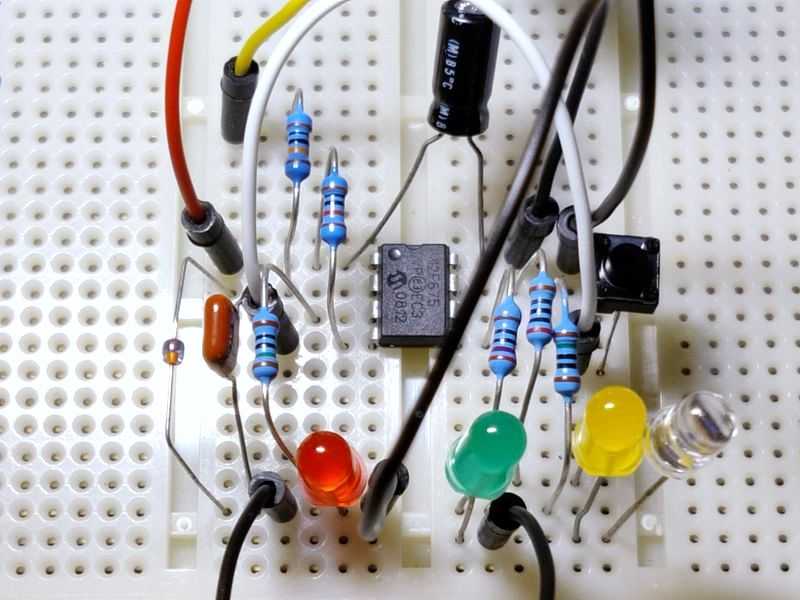
Above: The 4Mhz Crystal driven timer on a breadboard, using 33pF loading capacitors. The capacitor values are just a guess, but
accuracy was good!
As the code below has been reduced to two timers, it uses 211 words of ROM (just over 20%) but still uses 13 bytes of RAM.
The code below is for a 4Mhz crystal, but if you use a different speed, adjust the Bresenham total trim to the crystal speed / 4 / 16. For 4Mhz, that's 4000000 / 4 / 16 = 62500. For anything after than 4Mhz, you'll have a problem. An 8Mhz crystal, for example, would require 125000. That's bigger than the 16 bit unsigned integer (short) limit of 65535 I used for bres. Dividing by 32 instead of 16, gives 62500 but the ticks should be divided too using 256 / 32 = 8.
On 20Mhz, you'll still struggle. Even dividing by 64 takes you over the limit. Dividing by 128 could work when rounded down to 39062, but that means dividing the adjustment by 128 too, leaving 2 and 39062 always divides by 2 so it's not self-adjusting. Given the extra speed of the microprocessor clock, you should instead take the hit of the additional instructions required to support an unsigned long instead (these are 32 bit, so unsigned limit of 4,294,967,295). The program code memory required will be higher.
PIC12FTimer2.h
#ifndef _PIC12FTimer2_H_
#define _PIC12FTimer2_H_

#define TASK_INT_IOC 0
#define TASK_TIMER0_SEC 1
#define TASK_TIMER0_DEBOUNCE 2
#define RELAY (gpio.2)
#define BUTTON (gpio.3)
#define YELLOW (gpio.0)
#define GREEN (gpio.1)
#define TIME1 10  // First push timer - 10 minutes
#define TIME2 20  // Second push timer - 20 minutes

char iSec;
char iMin;
char iSetTime;
char cTask;
char iDebounceCounter;
char iDebounceTicks;

unsigned int bres = 0;

#endif //_PIC12FTimer2_H_
PIC12FTimer2.c
#include <system.h>
#include "PIC12FTimer2.h"

//Target PIC12F675 configuration word
#pragma DATA _CONFIG, _PWRTE_ON & _WDT_OFF & _XT_OSC & _CPD_OFF & _CP_OFF & _MCLRE_OFF & _BODEN_ON

//Set clock frequency
#pragma CLOCK_FREQ	4000000

void interrupt() {
    // Handle interrupt-on-change - button press
    if (intcon.GPIF && intcon.GPIE) {
        // Debounce - start timer0
        cTask.TASK_INT_IOC = 1;
        // read gpio
        char readgpio = gpio;
        intcon.GPIF = 0; // Clear interrupt flag
        intcon.GPIE = 0; // Disable interrupt (for de-bouncing)
    }

    // Handle timer0 interrupt
    if(intcon.T0IF && intcon.T0IE) {
        // uses 1 variable; unsigned 16 bit int bres
        // gets here every TMR0 int (every 256 ticks)
        // Count 1 second intervals
        bres += 16;	// add (256/16) ticks to bresenham total
        if (bres >= 62500) { // if reached 1 second (1000000/16)
            bres -= 62500; // subtract 1 second, retain error
            if (iSetTime) {
                // Tick 1 second
                iSec++;
                if (iSec == 60) {
                    // Tick minutes
                    iMin++;
                    iSec = 0;
                }
                cTask.TASK_TIMER0_SEC = 1;
            }
        }
        // Tick the debouce counter, if debounce counter less than 10x (500ms)
        if (iDebounceCounter < 10) {
            iDebounceTicks++;
            if (iDebounceTicks == 200) { // 200 ticks is roughly 50ms
                iDebounceCounter++;
                iDebounceTicks = 0;
                cTask.TASK_TIMER0_DEBOUNCE = 1;
            }
        }
        intcon.T0IF = 0; // Clear interrupt flag
    }
}

void initialise() {

    // Use oscillator callibration value by copying it to OSCCAL
    asm {
        call 0x3FF
        bsf _status, RP0
        movwf _osccal
        bcf _status, RP0
    }
    // GP0 = OUT: LED1
    // GP1 = OUT: LED2
    // GP2 = OUT: Relay trigger
    // GP3 = IN: push button
    // GP4 = OUT: LED3 or OSC2: 32kHz crystal
    // GP5 = N/A, T1 in or OSC1: 32kHz crystal
    trisio = 0b00001000;
    gpio = 0b00001000; // all LEDs/outputs off by default

    ansel = 0; // configure A/D inputs as digital I/O
    cmcon = 7; // compartor off

    // OPTION register - for TMR0 and Weak pull-ups config
    // set the prescaler to the WDT
    // Therefore, timer0 has NO prescaler and will overflow every 256 instructions
    // Bit 7 NOT_GPPU = 1 : disable pull ups
    // Bit 5 T0CS = 0: TMR0 Clock Source Select bit...0 = Internal Clock (CLKO) 1 = Transition on T0CKI pin
    // Bit 4 T0SE = 0: TMR0 Source Edge Select bit 0 = low/high 1 = high/low
    // Bit 3 PSA = 1: Prescaler Assignment bit...0 = Prescaler is assigned to watchdog timer WDT
    // Bits 2-0 PS2:PS0 = 000: Prescaler Rate Select bits, 000 = 1:1 prescaler
    option_reg = 0b10001000;

    // Setup for GP3 Interrupt [Button press]
    ioc.IOC3 = 1; // GP3 interrupt on change
    intcon.GPIE = 1; // GP3/RB0 Interrupt enabled (for button)

    // No task at initialisation
    cTask = 0;
    iDebounceCounter = 0;
    iDebounceTicks = 0;
    iSetTime = 0;
    iSec = 0;
    iMin = 0;

    // Enable interrupts
    intcon.GIE = 1;
    intcon.PEIE = 1;
}


void main() {
    initialise();

    // Endless loop
    while(1) {
        if (cTask.TASK_INT_IOC) {
            // Interrupt-on-change occured - start timer 0
            // Reset timer 0
            tmr0 = 0;
            bres = 0;
            iDebounceCounter = 0;
            iDebounceTicks = 0;
            // Enable timer 0 interrupt
            intcon.T0IE = 1;
            cTask.TASK_INT_IOC = 0;
        } else if (cTask.TASK_TIMER0_DEBOUNCE) {
            // Timer 0 counted 50ms
            // if debounce counter is 1, check state is still on
            if ((iDebounceCounter == 1) && (!BUTTON)) {
                // Button still pressed and debounced, set a timer
                if (iSetTime == 0) {
                    // This is the first timer, so reset seconds/minutes
                    iSec = 0;
                    iMin = 0;
                    // Also reset bresenham total
                    bres = 0;
                    // Set the timer to the first option
                    iSetTime = TIME1;
                    // Green LED
                    YELLOW = 0;
                    GREEN = 1;
                } else if (iSetTime == TIME1) {
                    iSetTime = TIME2;
                    // Yellow LED
                    YELLOW = 1;
                    GREEN = 0;
                } else {
                    iSetTime = 0;
                    // Off LEDs
                    //RED = 0;
                    YELLOW = 0;
                    GREEN = 0;
                }

                if (iSetTime > 0) {
                    // On relay and enable timer 1
                    RELAY = 1;
                } else {
                    // Off relay, disable timer 1
                    RELAY = 0;
                    intcon.T0IE = 0; // Disable timer 0 interrupt
                }
            } else if ((iDebounceCounter > 2) && (BUTTON)) {
                // Button released, interrupt can be enabled again
                intcon.GPIE = 1; // Enable interrupt
            }
            cTask.TASK_TIMER0_DEBOUNCE = 0;
        }

        if (cTask.TASK_TIMER0_SEC) {
            // Change LEDs based on minutes left
            if ((iSetTime - iMin) > TIME1) {
                YELLOW ^= 1; // toggle the yellow LED
                GREEN = 0;
            } else {
                YELLOW = 0;
                GREEN ^= 1;  // toggle the green LED
            }

            // Check if iMin reached setting
            if (iMin >= iSetTime) {
                // Time reached, switch off relay and reset
                RELAY = 0;
                // Turn off timer settings
                iSetTime = 0;
                // Off LEDs
                YELLOW = 0;
                GREEN = 0;
                // Off timer
                intcon.T0IE = 0; // Disable timer 0 interrupt
            }
            cTask.TASK_TIMER0_SEC = 0;
        }
        if (!intcon.T0IE) {
            // We can only sleep if the timer interrupt is off
            intcon.GPIE = 1; // ensure the button press interrupt is enabled before sleep
            sleep();
            nop(); // NOP must occur after wake up
        }
    }
}
Watch crystal based timer?
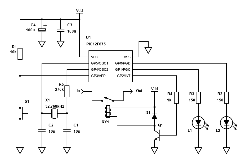
I did experiment with a 32.768kHz watch crystal to drive Timer 1. TL:DR, I failed to get this version accurate, but if you use a specific crystal with recommended capacitors and build a proper PCB for the project, this could be worth implementing.
The implementation would be based off the internal 4MHz oscillator running the PICs clock, with the 32.768kHz Crystal ticking Timer 1. Whilst this simple implementation could also have the 32kHz crystal running the main clock, that would make for a very slow processor with very little scope to implement more advanced functions.
For running Timer 1, a 32.768kHz watch crystal sits between OSC1 and OSC2 pins and should be loaded with capacitors from each pin to ground. T1OSCEN is set ON in this mode in order for the oscillator to start running. In this mode the timer1 can even generate interrupts during sleep, though we'll only be sleeping when the timer is off anyway.
A 32.768kHz crystal will tick the timer 32768 times a second. 32768 is 0x8000 in hex, so we must set TMR1H to 0x80 (and leave TMR1L as 0x00). T1CON must be set to 00001111 - that's TMR1CS (External clock from T1OSO/T1CKI pin), T1SYNC (Do not synchronize external clock input), T1OSCEN (LP oscillator is enabled for Timer1 clock) and TMRON to run the timer.
This implementation is certainly not as easy as I thought it would be though. I've built a few PIC circuits where the microcontroller's clock was driven off 4Mhz to 20Mhz crystals, and they've always worked. Knowing also that these timing crystals are used in millions of clocks and watches all over the world too, I naively though a 32.768kHz crystal oscillator circuit would be trivial.
Nope! With the external 32.768kHz crystal oscillator circuit, the crystal and it's loading capacitors really matters. A series resistor to prevent over-driving the crystal may also be required.
I didn't really achieve the success I wanted with this version as mine was at best 10 seconds short of counting to 10 minutes and changing the capacitors and resistors does affect the results (considerably!).
If you decide to go with this option, my recommendation is to buy the crystals off a well-known supplier that provides datasheets, so you have an idea of the capacitance required. An oscilloscope with 100x probe would be useful to monitor the output too. You'll also need to build the circuit on a proper PCB, with ground plane as any breadboard or Stripboard implementation will cause track/trace capacitance and affect the timing. See figure 7-4 in the PIC16F87/88 datasheet for example.
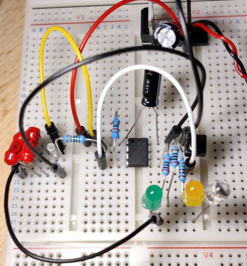
Above: The Crystal driven timer on a breadboard. Those ancient 5.6pF capacitors (the smallest value I had) gave me the best
results, but still far short of success.
The code for this timer is like the mains version below, but with a different T1CON and TMR1 settings and only support for two timers (like above). Since it's fiddly to get running, my recommendation is to use a 4Mhz (or similar MHz crystal) and run the PIC clock off that (see timer version above) as it's far easier to achieve reasonable accuracy.
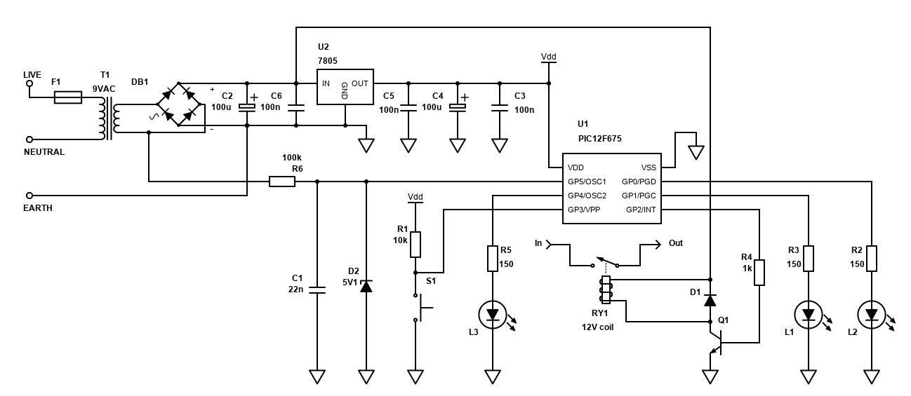
Mains AC driven timer
This is an alternative that frees up an additional IO pin, but at some additional circuit complexity. However, it's the most accurate timer that can be built and running for you without the software or hardware alterations that would be needed to get the first two versions accurate.
Most countries should keep the frequency of the mains alternating current at very near to either 50Hz or 60Hz. You'll need to know what frequency your mains voltage uses in order for this timer to be programmed correctly. Generally, most countries, including here in the UK, use 50Hz except the Americas (North, South and Central/Caribbean), which are usually 60Hz, but DO check your specific country though, and even check where you live in it (e.g., in Japan it could be either 50Hz in Tokyo or 60Hz in Kyoto).
You'll need to check if your country regulates an accurate timing on the mains frequency though. Generally, Europe and North America do, but South Asia and other grids may not. However, the frequency provided may still be accurate enough to drive a timer to your needs.
This AC frequency can then be used to increment the timer 1 within the PIC every 50 or 60 times a second. Many clocks use this method to keep time and it should be quite accurate.
The low voltage side of the AC from the PCB transformer output is used via a 100k current dropping resistor (R6) to feed the AC input into the GP5/T1CKI/OSC1/CLKIN pin. This input pin on the PIC has a Schmitt Trigger input buffer which means the AC sine wave can be feed directly instead of needing a true square wave signal. The 22nF capacitor C1 with R6 forms an RC low pass filter of around 72Hz. This means any frequency above 50Hz or 60Hz that should get filtered out and that will help the timer reliability by not false counting noise that appears on the mains from white-good appliances etc. The 5.1V Zener diode keeps the input voltage within a safe margin of the supply voltage (5V).
This timer is perhaps better for longer periods of delays though because short term power fluctuations mean that the frequency could be slightly above or below (say) 50Hz - so still a 15 minute or 30 minute timer may not be as accurate as a well configured crystal oscillator. A 20 hour timer may be more accurate though.
The mains timer method is what I wanted to use for my towel rack timer, but at the time I didn't quite have the correct circuit and code to make it work so my real timer just uses the internal oscillator, with the necessary TMR1HV and TMR1LV preset value adjustments in order to get a reasonably accurate (not perfect, but good enough for the application) 15 minute interval.
Above: The AC driven timer on a breadboard.
Above: The AC driven timer on a breadboard - closer view.
In my breadboard build though, and with some more research, I managed to get an AC driven timer to work fine. With minimal time I managed to build a timer that was as accurate as I could time it without the fiddling of timer overflows for the simple timer or capacitors / crystals in the second timer.
The disadvantage of course is you need to have the AC signal. This means you cannot use common 5V DC adaptors. Using AC adaptors would work fine though and for testing I used a 15V AC wall-wart and this drove the timer fine. To power the PIC, I used a small bridge rectifier to convert the AC to DC and a 7805 voltage regulator to drop the unregulated DC to a regulated 5V DC for the PIC.
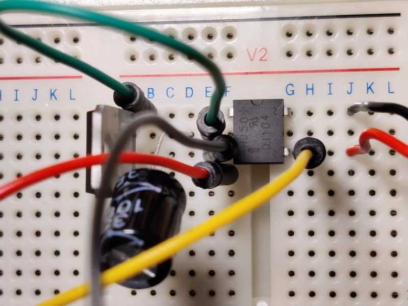
Above: This DI104 DIP bridge rectifier converts the AC to DC. 4x 1N4001 diodes would also work fine. A 100µF capacitor (or
higher) should follow it.
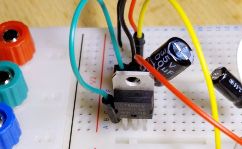
Above: A 7805 regulated is ideal for dropping the unregulated DC to a smooth 5V output for the PIC. 78L05 will also be fine.
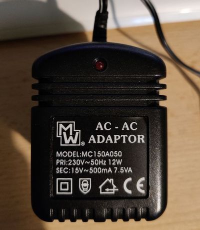
Above: An AC-AC transformer like this will work if you don't need to do mains wiring or use it in a bathroom. Aim for 9VAC for the
best efficiency.
Since the PIC draws very little current, a simple 5V linear regulator like this is perfectly fine. You could also use a small switching regulator module if you prefer too, but with such low current draw the efficiency of a switching PSU may not be better. The current draw will be higher when the relay is on if you use a 5V relay. You could instead use a 12V relay and drive that off the unregulated DC after the bridge rectifier, assuming you input was 9VAC - see schematic below.
The code for this timer is simple and shouldn't need to be altered much. On the PIC12F675, 221 words of ROM is used (21.6%) and 10 bytes of RAM is required (15.7%), leaving room for expansion.
PIC12FTimer3.h
#ifndef _PIC12FTimer3_H_
#define _PIC12FTimer3_H_

#define MAINS_FREQ 50 // the local mains supply frequency
#define MAINS_DLY 0xFF - MAINS_FREQ + 1 // the delay value for timer 1 based on local supply

#define TASK_INT_IOC 0
#define TASK_TIMER0 1
#define TASK_TIMER1 2
#define RELAY (gpio.2)
#define BUTTON (gpio.3)
#define RED (gpio.4)
#define YELLOW (gpio.0)
#define GREEN (gpio.1)
#define TIME1 1  // First push timer - 10 minutes
#define TIME2 2  // Second push timer - 30 minutes
#define TIME3 3  // Third push timer - 45 minutes
// For mains, set TMR1H to 0xFF and TMR1L to MAINS_DLY
// This means timer 1 will overflow when 50 cycles are complete, generating the interrupt
#define TMR1HV 0xFF
#define TMR1LV MAINS_DLY
#define TMR0PRESET 61

char iSec;
char iMin;
char iSetTime;
char cTask;
char iDebounceCounter;

#endif //_PIC12FTimer3_H_
PIC12FTimer3.c
#include <system.h>
#include "PIC12FTimer3.h"

//Target PIC12F675 configuration word
#pragma DATA _CONFIG, _PWRTE_ON & _WDT_OFF & _INTRC_OSC_NOCLKOUT & _CPD_OFF & _CP_OFF & _MCLRE_OFF & _BODEN_ON

//Set clock frequency
#pragma CLOCK_FREQ	4000000


void interrupt() {
    // Handle interrupt-on-change - button press
    if (intcon.GPIF && intcon.GPIE) {
        // Debounce - start timer0
        cTask.TASK_INT_IOC = 1;
        // read gpio
        char readgpio = gpio;
        intcon.GPIF = 0; // Clear interrupt flag
        intcon.GPIE = 0; // Disable interrupt (for de-bouncing)
    }

    // Handle timer0 interrupt - button debounce
    if(intcon.T0IF && intcon.T0IE) {
        tmr0 = TMR0PRESET; // preset for timer0 register
        iDebounceCounter++;
        intcon.T0IF = 0; // Clear interrupt flag
        cTask.TASK_TIMER0 = 1;
    }

    // Handle timer1 interrupt - delay counter
    if (pir1.TMR1IF && pie1.TMR1IE) {
        tmr1h = TMR1HV;      // preset for timer1 MSB register
        tmr1l = TMR1LV;      // preset for timer1 LSB register

        // Tick seconds
        iSec++;
        if (iSec >= 60) {
            // Tick minutes
            iMin++;
            iSec = 0;
        }
        pir1.TMR1IF = 0;     // Clear interrupt flag
        cTask.TASK_TIMER1 = 1;
    }
}

void initialise() {
    // GP0 = OUT: LED1
    // GP1 = OUT: LED2
    // GP2 = OUT: Relay trigger
    // GP3 = IN: push button
    // GP4 = OUT: LED3 or OSC2: 32kHz crystal
    // GP5 = N/A, T1 in or OSC1: 32kHz crystal
    trisio = 0b00001000;
    gpio = 0b00001000; // all LEDs/outputs off by default

    ansel = 0; // configure A/D inputs as digital I/O
    cmcon = 7; // compartor off

    // OPTION register - for TMR0 and Weak pull-ups config
    // Bit 7 NOT_GPPU = 1 : disable pull ups
    // Bit 5 T0CS = 0: TMR0 Clock Source Select bit...0 = Internal Clock (CLKO) 1 = Transition on T0CKI pin
    // Bit 4 T0SE = 0: TMR0 Source Edge Select bit 0 = low/high 1 = high/low
    // Bit 3 PSA = 0: Prescaler Assignment bit...0 = Prescaler is assigned to the Timer0
    // Bits 2-0 PS2:PS0 = 111: Prescaler Rate Select bits, 111 = 1:256 prescaler
    option_reg = 0b10000111;
    //Timer0 Registers Prescaler= 256 - TMR0 Preset = 61 - Freq = 20.03 Hz - Period = 0.049920 seconds
    tmr0 = TMR0PRESET; // preset for timer0 register

    // Timer 1 setup - interrupt on AC 50Hz
    // Timer1 Registers Prescaler= 1 - TMR1 Preset = 65486 - Freq = 1 Hz from 50Hz
    // Bits 5-4 T1CKPS1:T1CKPS0 = 00: Prescaler Rate Select bits, 00 = 1:1 prescaler
    // Bit 3 T1OSCEN = 0: Timer1 LP Oscillator Enable Control bit, 0 = off
    // Bit 2 NOT_T1SYNC = 1: Timer1 External Clock Input Synchronization Control bit, 1 = Do not synchronize external clock input
    // Bit 1 TMR1CS = 1: Timer1 Clock Source Select bit, 1 = External clock from T1OSO/T1CKI pin (on the rising edge)
    // Bit 0 TMR1ON = 0: Timer1 On Bit, 0 = off
    t1con = 0b00000110;
    tmr1h = TMR1HV;      // preset for timer1 MSB register
    tmr1l = TMR1LV;      // preset for timer1 LSB register
    pie1.TMR1IE = 1;     // Timer 1 interrupt

    // Setup for GP3 Interrupt [Button press]
    ioc.IOC3 = 1; // GP3 interrupt on change
    intcon.GPIE = 1; // GP3/RB0 Interrupt enabled (for button)

    // No task at initialisation
    cTask = 0;
    iDebounceCounter = 0;
    iSetTime = 0;
    iSec = 0;
    iMin = 0;

    // Enable interrupts
    intcon.GIE = 1;
    intcon.PEIE = 1;
}


void main() {
    initialise();

    // Endless loop
    while(1) {
        if (cTask.TASK_INT_IOC) {
            // Interrupt-on-change occured - start timer 0
            // Reset timer 0
            tmr0 = TMR0PRESET;
            // Enable timer 0 interrupt
            intcon.T0IE = 1;
            cTask.TASK_INT_IOC = 0;
        } else if (cTask.TASK_TIMER0) {
            // Timer complete
            // if debounce counter is 1, check state is still on
            if ((iDebounceCounter == 1) && (!BUTTON)) {
                // Button still pressed and debounced, set a timer
                if (iSetTime == 0) {
                    iSetTime = TIME1;
                    // Green LED
                    RED = 0;
                    YELLOW = 0;
                    GREEN = 1;
                } else if (iSetTime == TIME1) {
                    iSetTime = TIME2;
                    // Yellow LED
                    RED = 0;
                    YELLOW = 1;
                    GREEN = 0;
                } else if (iSetTime == TIME2) {
                    iSetTime = TIME3;
                    // Red LED
                    RED = 1;
                    YELLOW = 0;
                    GREEN = 0;
                } else {
                    iSetTime = 0;
                    // Off LEDs
                    RED = 0;
                    YELLOW = 0;
                    GREEN = 0;
                }

                if (iSetTime > 0) {
                    // On relay and enable timer 1
                    RELAY = 1;
                    t1con.TMR1ON = 1; // Enable Timer 1
                } else {
                    // Off relay, disable timer 1
                    RELAY = 0;
                    iSec = 0;
                    iMin = 0;
                    t1con.TMR1ON = 0; // Disable Timer 1
                }
            } else if ((iDebounceCounter > 2) && (BUTTON)) {
                // Button released, interrupt can be enabled again
                intcon.GPIE = 1; // Enable interrupt
                intcon.T0IE = 0; // Disable timer 0 interrupt
                iDebounceCounter = 0;
            }
            cTask.TASK_TIMER0 = 0;
        }

        if (cTask.TASK_TIMER1) {

            // Change LEDs based on minutes left
            if ((iSetTime - iMin) > TIME2) {
                RED ^= 1; // toggle the red LED
                YELLOW = 0;
                GREEN = 0;
            } else if ((iSetTime - iMin) > TIME1) {
                RED = 0;
                YELLOW ^= 1; // toggle the yellow LED
                GREEN = 0;
            } else {
                RED = 0;
                YELLOW = 0;
                GREEN ^= 1;  // toggle the green LED
            }


            // Check if iMin reached setting
            if (iMin >= iSetTime) {
                // Time reached, switch off relay and reset
                RELAY = 0;
                // Reset time
                iSec = 0;
                iMin = 0;
                iSetTime = 0;
                // Off LEDs
                RED = 0;
                YELLOW = 0;
                GREEN = 0;
                // Off timer
                t1con.TMR1ON = 0;
            }
            cTask.TASK_TIMER1 = 0;
        }
        if (!t1con.TMR1ON && !intcon.T0IE) {
            // We can only sleep if the timers are off
            intcon.GPIE = 1; // ensure the button press interrupt is enabled
            sleep();
            nop(); // NOP must occur after wake up
        }
    }
}
Real Time Clock (RTC) Timer
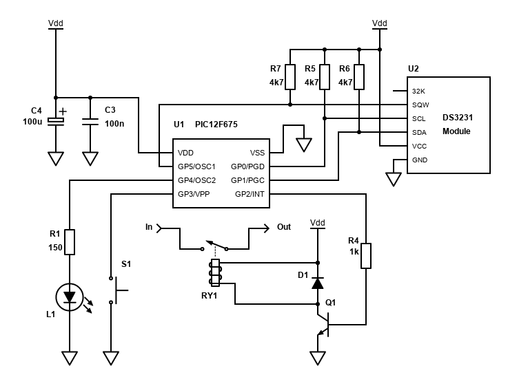
Finally, a fourth timer option is one that is built using a Real Time Clock RTC chip.
I picked a DS3231 module (which turned out to be a DS3231M) as well as a DS3231SN module to experiment with. These chips from Maxim Integrated have an oscillator built in. The DS3231(SN) actually has a crystal built into it and is factory configured to be only a couple of minutes out in a whole year. The DS3231M uses a slightly less impressive MEMS resonator built in which is temperature compensated and should be only less than half a second out per day (so about 3 minutes in a year).
Both of those should meet the accuracy needed for the kind of timer featured here, however using them does increase the cost and complexity of the circuit.
I did try just powering the modules by +5V and seeing if the 32K output (which seems to be enabled by default) would allow us to use these chips to drive the PIC timer directly via GP5/OSC1, without any I2C bus at all. Under testing though, I found the 32k clock runs for about 200ms for the DS3231M module, or 54ms for the DS3231SN module, then stops with a longer pulse and then stays low.
This means to use the DS3231 modules, we'll need to communicate with them over the two wire I2C (Inter-Integrated Circuit) bus. We'll need three pins now - two for the bus, and one for either the 32K signal, or the square wave/alarm signal. It would be possible to just use the I2C bus, but the PIC would need to poll for the timer state. It seems wasteful and would lose a bit of accuracy.
In this timer we don't really care about the date, we just care about the number of minutes that have passed since activating the timer. My code suggestion basically sets the date to 1/1/1900 00:00 when the power is applied.
The square wave output seemed to me the best option to for the timer. This can be used to directly drive the PICs Timer 1 on via the GP5/T1CKI/OSC1/CLKIN pin. The I2C communication will be done on the GP0 and GP1 pins, leaving GP2 to drive the relay, GP4 to drive a single LED and GP3 to have the push button switch connected to it.
This means only one timer is implemented on the PIC12F675. Of course, you could pick another PIC with more I/O to allow the three timers again though. The PIC16F627(A) would be ideal, or PIC16F1824 even better for the hardware I2C. Just two suggestions though, many will work!
So, what's the implementation?
- At initialisation, the date is set in the DS3231 as 1/1/1900 00:00. This implementation does not care about the date as doing so adds considerably to the amount PIC ROM and RAM required, as long variables will be needed to store the date and time accurately and functions that divide / multiply in order to convert the decimal format dates to BCD (binary coded decimal) format that the DS3231 expects and sends.
- The oscillator is disabled at power on (OSF set to 0). It's only needed when the timer is activated.
- The Interrupt Control (INTCN) option is to 0, enabling the square wave output. With RS1 and RS2 set to 0 too, the square wave frequency is 1Hz.
- When the timer is activated, the oscillator on the DS3231 is enabled, the PIC's Timer 1 is reset and will start counting.
Because of the I2C library required, the code is a fair bit heavier, requiring 451 words of ROM and 24 bytes of RAM. Both those are nearly half of what's available. The I2C implementation is software based, using BoostC inbuilt library i2c_driver.h.
It works very similar to the mains AC timer above though, just with the extra I2C commands to enable/disable the oscillator and perform the initial setup of the DS3231.
Note: If your PIC has a hardware MSSP/SSP module, then the code can be adjusted to use hardware I2C. This reduces the amount of code required and allows somewhat asynchronous communication. The built in i2c_driver.h code can be modified for hardware use, or you can roll your own like I did for my TDA7439 amplifier. You must use specific pins though (e.g., RC0 and RC1 for the PIC16F1824).
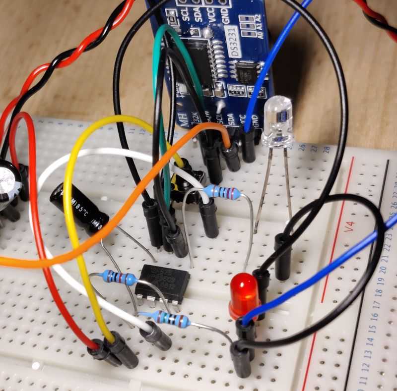
Above: The DS3231 driven timer on a breadboard.
I used a commonly available DS3231 module for testing (from eBay), which actually came DS3231M chip (bad advertising!). I've seen the same layout named the ZS-042 module. On testing to try and get the 32K output working without I2C I modified it to remove the charging circuit (advisable anyway) and short the VBAT pin to ground adjacent to it for running without a battery, but I don't think that's at all required.
The ZS-042 module comes with pull up resistors built in for the I2C SDA/SCL, as well as the 32K and INT/SQW outputs so you don't need R5, R6 and R7 from the schematic above. Other modules may need them though.
The ZS-042 also comes with a AT24C32 EEPROM with 32K storage capacity. Most PICs have built in EEPROM (including the cheap PIC12F675), so unlikely you'll ever need it unless you want to retain data after removing power (i.e., for an alarm clock radio).
Caveat: I've only tested this code briefly, not over a long period of time. It should be fine, but don't take it for granted for mission critical work!
PIC12FTimer4.h
#ifndef _PIC12FTimer4_H_
#define _PIC12FTimer4_H_

#define TASK_INT_IOC 0
#define TASK_TIMER0 1
#define TASK_TIMER1 2
#define RELAY (gpio.2)
#define BUTTON (gpio.3)
#define RED (gpio.4)
#define TIME1 1  // First push timer - 10 minutes
// For DS321 1Hz square wave, set both TMR1H and TRM1L to 0xFF
// This means timer 1 will overflow when 1 cycle completes, generating the interrupt
#define TMR1HV 0xFF
#define TMR1LV 0xFF
#define TMR0PRESET 61

char iSec;
char iMin;
char iSetTime;
char cTask;
char iDebounceCounter;

// i2c options
#define use_i2c_SW
// clock SCL on GP0, data SDA on GP1
#define i2c_ARGS	0, GPIO, TRISIO, 1, GPIO, TRISIO, e_SSPCON1, e_SSPCON2, \
					e_SSPSTAT, e_SSPBUF, e_SSPIF_BIT, e_SSPIF_PIR,			\
					e_BCLIF_BIT, e_BCLIF_PIR, 7, e_SSPADD, (i2c_reset_wdt | i2c_SMP)
// RAM used by the software i2c driver to emulate the equivalent i2c hardware registers
unsigned short swi2c_SSPCON1@0x40;	// define location for the emulated SSPCON1
unsigned short swi2c_SSPCON2@0x41;	// define location for the emulated SSPCON2
unsigned short swi2c_SSPSTAT@0x42;	// define location for the emulated SSPSTAT
unsigned short swi2c_SSPBUF@0x43;	// define location for the emulated SSPBUF
unsigned short swi2c_SSPIF_PIR@0x44;// define location for the emulated SSPIF_PIR
unsigned short swi2c_BCLIF_PIR@0x45;// define location for the emulated BCLIF_PIR
unsigned short swi2c_SSPADD@0x46;	// define location for the emulated SSPADD
#define e_SSPCON1	0x40
#define e_SSPCON2	0x41
#define e_SSPSTAT	0x42
#define e_SSPADD	0x43
#define e_SSPBUF	0x44
#define e_SSPIF_PIR	0x45
#define e_BCLIF_PIR	0x46
#define e_SSPIF_BIT	3
#define e_BCLIF_BIT	3

#define ds3231_addr 0xD0

#endif //_PIC12FTimer4_H_
PIC12FTimer4.c
#include <system.h>
#include <i2c_driver.h>
#include "PIC12FTimer4.h"

//Target PIC12F675 configuration word
#pragma DATA _CONFIG, _PWRTE_ON & _WDT_OFF & _INTRC_OSC_NOCLKOUT & _CPD_OFF & _CP_OFF & _MCLRE_OFF & _BODEN_ON

//Set clock frequency
#pragma CLOCK_FREQ	4000000

void interrupt() {
    // Handle interrupt-on-change - button press
    if (intcon.GPIF && intcon.GPIE) {
        // Debounce - start timer0
        cTask.TASK_INT_IOC = 1;
        // read gpio
        char readgpio = gpio;
        intcon.GPIF = 0; // Clear interrupt flag
        intcon.GPIE = 0; // Disable interrupt (for de-bouncing)
    }

    // Handle timer0 interrupt - button debounce
    if(intcon.T0IF && intcon.T0IE) {
        tmr0 = TMR0PRESET; // preset for timer0 register
        iDebounceCounter++;
        intcon.T0IF = 0; // Clear interrupt flag
        cTask.TASK_TIMER0 = 1;
    }

    // Handle timer1 interrupt - delay counter
    if (pir1.TMR1IF && pie1.TMR1IE) {
        tmr1h = TMR1HV;      // preset for timer1 MSB register
        tmr1l = TMR1LV;      // preset for timer1 LSB register

        // Tick seconds
        iSec++;
        if (iSec >= 60) {
            // Tick minutes
            iMin++;
            iSec = 0;
        }
        pir1.TMR1IF = 0;     // Clear interrupt flag
        cTask.TASK_TIMER1 = 1;
    }
}

void ds3231Write(char ds3231Reg, char byteOut) {
    i2c_start();
    i2c_write(ds3231_addr); // address + write
    i2c_write(ds3231Reg); // start at address
    i2c_write(byteOut); // start at address
    i2c_stop();
}

void ds3231Init() {
  /* control register 0Eh
    bit7 EOSC   Enable Oscillator (1 if oscillator must be stopped when on battery)
    bit6 BBSQW  Battery Backed Square Wave
    bit5 CONV   Convert temperature (1 forces a conversion NOW)
    bit4 RS2    Rate select - frequency of square wave output
    bit3 RS1    Rate select
    bit2 INTCN  Interrupt control (1 for use of the alarms and to disable square wave)
    bit1 A2IE   Alarm2 interrupt enable (1 to enable)
    bit0 A1IE   Alarm1 interrupt enable (1 to enable)
    */
    ds3231Write(0x0E, 0x80);
    /* Status Register 0Fh
    bit7 OSF     Oscillator Stop Flag
    bit3 EN32kHz Enable 32kHz Output
    bit2 BSY     Busy
    bit1 A2F     Alarm 2 Flag
    bit0 A1F     Alarm 1 Flag
    */
    ds3231Write(0x0F, 0x80);
}

void ds3231Start() {
    ds3231Write(0x0F, 0x00);
}

void ds3231Stop() {
    ds3231Write(0x0F, 0x80);
}

void ds3231WriteDate() {
	i2c_start();
	i2c_write(ds3231_addr); // address + write
	i2c_write(0); // start at address 0
	i2c_write(0); // seconds
	i2c_write(0); // minutes
	i2c_write(0); // hours
	i2c_write(1); // day
	i2c_write(1); // month + century
	i2c_write(0); // year - 0
	i2c_stop();
}

void initialise() {
    // Use oscillator callibration value by copying it to OSCCAL
    asm {
        call 0x3FF
        bsf _status, RP0
        movwf _osccal
        bcf _status, RP0
    }
    // GP0 = IN/OUT: I2C SCL
    // GP1 = IN/OUT, I2C SDA
    // GP2 = OUT: Relay trigger
    // GP3 = IN: push button
    // GP4 = OUT: LED
    // GP5 = IN: SQW input
    trisio = 0b00101011;
    gpio = 0b00001000; // all LEDs/outputs off by default

    ansel = 0; // configure A/D inputs as digital I/O
    cmcon = 7; // compartor off

    // OPTION register - for TMR0 and Weak pull-ups config
    // Bit 7 NOT_GPPU = 1 : disable pull ups
    // Bit 5 T0CS = 0: TMR0 Clock Source Select bit...0 = Internal Clock (CLKO) 1 = Transition on T0CKI pin
    // Bit 4 T0SE = 0: TMR0 Source Edge Select bit 0 = low/high 1 = high/low
    // Bit 3 PSA = 0: Prescaler Assignment bit...0 = Prescaler is assigned to the Timer0
    // Bits 2-0 PS2:PS0 = 111: Prescaler Rate Select bits, 111 = 1:256 prescaler
    option_reg = 0x1000111;
    //Timer0 Registers Prescaler= 256 - TMR0 Preset = 61 - Freq = 20.03 Hz - Period = 0.049920 seconds
    tmr0 = TMR0PRESET; // preset for timer0 register

    // Timer 1 setup - interrupt on DS3231 SQW 1Hz
    // Timer1 Registers Prescaler= 1 - TMR1 Preset = 65535 - Freq = 1 Hz
    // Bits 5-4 T1CKPS1:T1CKPS0 = 00: Prescaler Rate Select bits, 00 = 1:1 prescaler
    // Bit 3 T1OSCEN = 0: Timer1 LP Oscillator Enable Control bit, 0 = off
    // Bit 2 NOT_T1SYNC = 1: Timer1 External Clock Input Synchronization Control bit, 1 = Do not synchronize external clock input
    // Bit 1 TMR1CS = 1: Timer1 Clock Source Select bit, 1 = External clock from T1OSO/T1CKI pin (on the rising edge)
    // Bit 0 TMR1ON = 0: Timer1 On Bit, 0 = off
    t1con = 0b00000110;
    tmr1h = TMR1HV;      // preset for timer1 MSB register
    tmr1l = TMR1LV;      // preset for timer1 LSB register
    pie1.TMR1IE = 1;     // Timer 1 interrupt

    // Setup for GP3 Interrupt [Button press]
    ioc.IOC3 = 1; // GP3 interrupt on change
    intcon.GPIE = 1; // GP3/RB0 Interrupt enabled (for button)

    // No task at initialisation
    cTask = 0;
    iDebounceCounter = 0;
    iSetTime = 0;
    iSec = 0;
    iMin = 0;

    i2c_init(1);
    ds3231WriteDate();
    ds3231Init();

    // Enable interrupts
    intcon.GIE = 1;
    intcon.PEIE = 1;
}


void main() {
    initialise();

    // Endless loop
    while(1) {
        if (cTask.TASK_INT_IOC) {
            // Interrupt-on-change occured - start timer 0
            // Reset timer 0
            tmr0 = TMR0PRESET;
            // Enable timer 0 interrupt
            intcon.T0IE = 1;
            cTask.TASK_INT_IOC = 0;
        } else if (cTask.TASK_TIMER0) {
            // Timer complete
            // if debounce counter is 1, check state is still on
            if ((iDebounceCounter == 1) && (!BUTTON)) {
                // Button still pressed and debounced, set a timer
                if (iSetTime == 0) {
                    iSetTime = TIME1;
                    // Start the DS3231 on the first timer
                    ds3231Start();
                    // Red LED
                    RED = 1;
                    // On relay and enable timer 1
                    RELAY = 1;
                    t1con.TMR1ON = 1; // Enable Timer 1
                } else {
                    iSetTime = 0;
                    // Off LEDs
                    RED = 0;
                    // Off relay, disable timer 1
                    RELAY = 0;
                    iSec = 0;
                    iMin = 0;
                    // Disable Timer 1
                    t1con.TMR1ON = 0;
                    // Stop DS3231
                    ds3231Stop();
                }
            } else if ((iDebounceCounter > 2) && (BUTTON)) {
                // Button released, interrupt can be enabled again
                intcon.GPIE = 1; // Enable interrupt
                intcon.T0IE = 0; // Disable timer 0 interrupt
                iDebounceCounter = 0;
            }
            cTask.TASK_TIMER0 = 0;
        }

        if (cTask.TASK_TIMER1) {
            RED ^= 1; // toggle the red LED

            // Check if iMin reached setting
            if (iMin >= iSetTime) {
                // Time reached, switch off relay and reset
                RELAY = 0;
                // Reset time
                iSec = 0;
                iMin = 0;
                iSetTime = 0;
                // Off LEDs
                RED = 0;
                // Disable Timer 1
                t1con.TMR1ON = 0;
                // Stop DS3231
                ds3231Stop();
            }
            cTask.TASK_TIMER1 = 0;
        }
        if (!t1con.TMR1ON && !intcon.T0IE) {
            // We can only sleep if the timers are off
            intcon.GPIE = 1; // ensure the button press interrupt is enabled
            sleep();
            nop(); // NOP must occur after wake up
        }
    }
}
Conclusion
Below are some pictures of the real-life towel rack timer I built years ago. As mentioned, it was originally based on the 3rd timer (mains driven) but due to some design errors I made it based on the internal oscillator and adjusted the TMR1 16 bit register value as appropriate to get it close to 15, 30 and 45 minutes. I used a PIC16F627A since that's what I had at the time only, and PCB mount transformer and relays, which are all mounted on a DIY PCB (see my PCB building guide for how I make these). An ICSP header has been included too so I may easily load an updated program to it.
I used IEC/kettle connectors and chopped in half an IEC extension existing cable as the cable in the existing towel rack was easy enough to rewire, and the wall spur easy to wire in to. If you do the same, please note that the input side (from the wall) should be a female plug and male socket, so you can't accidentally electrocute yourself on the cable, and the output side is a female socket so you can't accidentally electrocute yourself on the timer output (if it's on and no cable plugged in).
I soldered the sockets at the time, but this is not advised, and you should use insulated quick-connect/spade connectors, crimped to the wire.
If you do build something like this in the bathroom, make sure the mains cables (in and out) have enough slack to drop below the input/output sockets and the wall/towel rack. This is to ensure that any water/damp runs down the cable and drips at the bottom of the curve, rather than running into the socket.
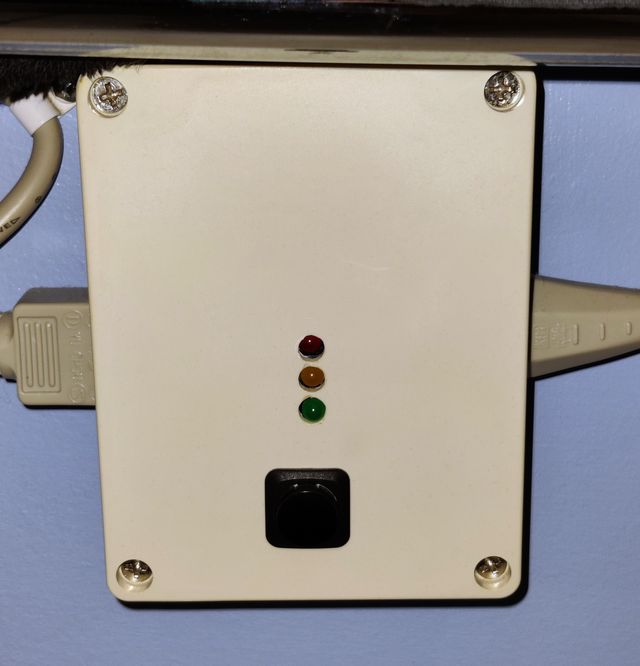
Above: Front view, mounted to the wall and under the towel rack.
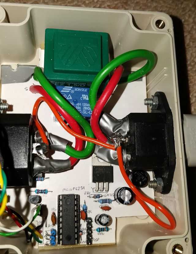
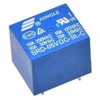
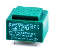
Above: Inside view. Top is a PCB transformer (green) Breve Tufvassons TEZ1.5/D/9V, below is a mains rated relay Songle
SRD-12VDC-SL-C (blue), input socket on the right, output (switched) socket on the left, regulated voltage using LM317T, PIC16F627A and
associated components at the bottom.
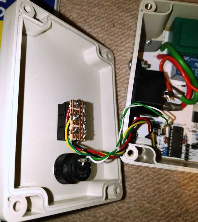
Above: View of the LEDs and switch mounted under the front. The LEDs are mounted on Stripboard.
It's worked for more than five years completely fine, though we don't use it in the summer, and I'd say it's saved its cost on electric bills, or it will do in the next few years for sure!
My recommendation though from the four options I've described is to use the mains driven timer from a low voltage AC transformer, or the timer based on the external 4Mhz (or similar) crystal. They are both accurate and still simple. The first circuit is the simplest though and you can go with that too if you're happy to adjust the program several times in order to get the timer off the internal oscillator correct.
My first and in-use timer used the PIC16F627A, but I've written this up using the PIC12F675, basically one of the smallest and least powerful microcontrollers they created. This should easily adjust and work on any of Microchip's PIC12, PIC16 or PIC18 range though and its simplicity allows scope to expand the code further for more advanced use, if you need it!
References and more reading:
- Source code on github.com
- PIC12F675 datasheet
- PCB building guide
- SourceBoost Technologies - low cost, high performance cross compilers
- UsbPicProg - Open Source Microchip PIC programmer
- Elliott Sound Products - Solid State Relays, Types & Usage
- Elliott Sound Products - Relays, Selection & Usage (Part 1)
- Elliott Sound Products - Relays (Part 2), Contact Protection Schemes
- HW Group - How (not) to destroy a relay
- Homemade Circuit Projects - Transistor Relay Driver Circuit with Formula and Calculations
- Mr Vis Education - Transistor Base Resistor Calculator
- Dring Engineering Services - IC Timer Calculator and Source Code Generator
- RomanBlack.com - Zero-error 1 second Timer
- Picprojects - Test For Presence of Internal Oscillator Calibration Word
- Picprojects - Internal Oscillator Recalibration Utility
- Electro-tech-online.com Forums - Timer1 with PIC16F628a and 32.768KHz Crystal
- PIC16F87/88 Datasheet - Page 77 32.768kHz timer example
- All About Circuits Forums - Project: PIC 4-Digit Single-Chip 24 Hour Clock
- Hackaday - Using A/C Frequency As A Clock Signal
- Embedded Lab - Lab 7: PIC Timers and Counters (Part 1)
- Microchip Developer Help - Timer 1 Secondary Oscillator
- Microchip AN949 - Making Your Oscillator Work
- Microchip forums - Timer1 on 32KHz Crystal?
- DS3231 datasheet
- DS3231M datasheet