
Tone Control circuits
Ah - the humble tone control. Rotating those knobs, hearing the change in bass or treble and its impact on the music track is a nostalgic feeling worth adding to DIY audio projects. They also help make less than decent speakers, track recordings or poor room acoustics sound more reasonable.
Tone controls have been around years. The circuits here use the popular Baxandall method published in 1952, before even transistors became common! It's a useful circuit though and most of my amplifier builds have included a tone control, with the exception of my high end Hi-Fi amplifier and my small speaker builds due to size constraints.
Do note that the Baxandall tone control is not as versatile as parametric EQ, or modern Digital Sound Processing (DSP) - both give far more control. The more than 70 year old design though is still a good way to add some frequency control into your project and is far cheaper and easily than others. If you are interested in a digital controlled EQ though, you can see my TDA7317 article.
Tone controls circuits should be positioned after your source but connected before the amplifier, ideally before the volume control.
For Hi-Fi systems, Rod at ESP has various pre-amplifiers featuring tone controls, and these are best designs for such systems - see ESP Project 94 Universal Preamp / Mixer and Hi-Fi Tone-Control Preamplifier for two examples, as well as the interesting Versatile Tone Control.
Whilst there are a few passive (needs no power) and transistor designs elsewhere on the net, some of these will not perform well and using op-amps gives the best performance.
There's a lack of single supply tone control designs using op-amps though, so this article contains information about how to modify such circuit for single supply use for battery powered, portable systems and car use where integrating a split supply complicates things. This gives you the ability to combine this circuit into a powered speaker project using a single supply amp such as the popular LM386 and TDA7297 amplifiers.
Also shown is how to modify the circuit to add a middle control, and an layouts for hobbyists to build on stripboard.
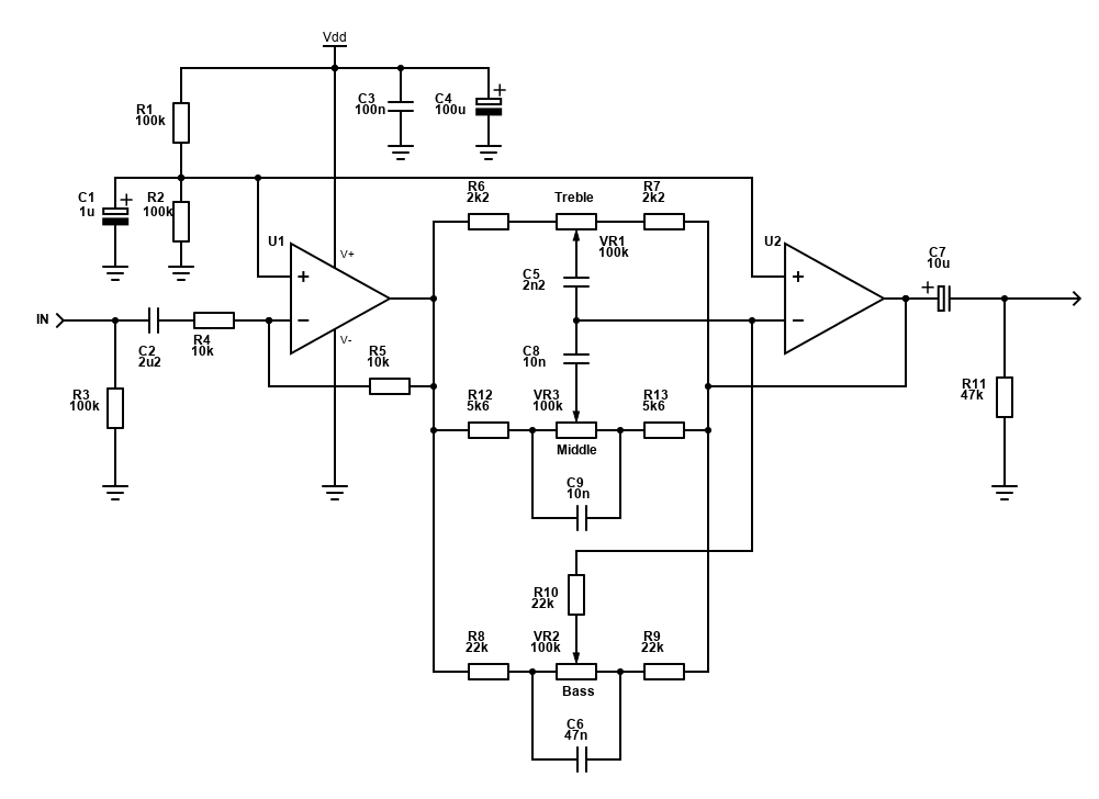
Single supply active tone control
This circuit is mainly a replica of ESP Project 94. This is because this circuit has ideal choice of component values for a (better) mid-point of 640Hz instead of the standard 1kHz, as well as a sensible selection of capacitor and resistor combinations that should be easy find.
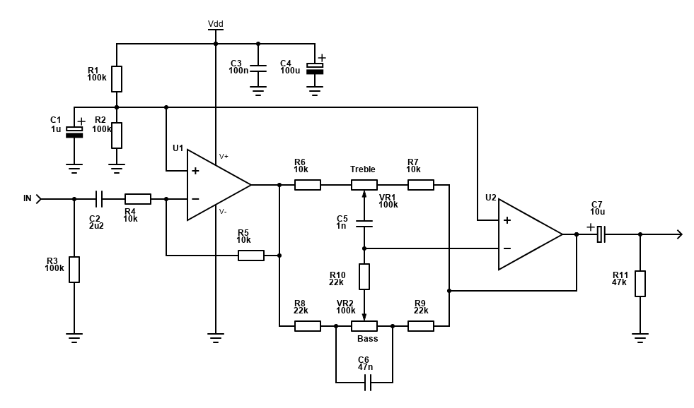
The components VR1 and VR2 are variable resistors known as potentiometers (or 'pots'). They should be 100k linear type (not log).
The schematic is for one channel only and you should duplicate all components for stereo use, though you can use ½ voltage reference created by R1, R2 and C2 to feed the +ve inputs of the second channel. For stereo systems, you can buy dual potentiometers which allow you to adjust the setting for both channels at once.
The ESP circuit has been adjusted for single supply use, for example +12V or +9V. This involves some additional components.
As audio signals are AC, they should have a voltage that alternates above and below the ground reference (0V). A 1V RMS audio signal will go from a peak of +1.414V to −1.414V. If we connect the operational amplifiers −Vs pin to ground, it can't go below 0V for a rail-to-rail op-amp (and, for most operational amplifiers, these won't reach below 1V).
To resolve that, a common way (and what's used here) is to use a voltage divider to offset the input signal to the op-amp, creating a virtual ground reference. The circuit above does that, offsetting the signal by adding half the voltage (i.e., 4.5V for 9V) to the AC signal. This allows the amplified AC signal to go negative up to -3V and positive up to 3V (a little above 2V RMS).
There are some disadvantages to single supply designs with virtual grounds:
- You need to use some more components. For split rail operation you can reduce the component count.
- Less stability - fluctuations on the power supply, hiss and hum can be injected into the input signal.
- Low frequency cut-off - there are high pass filters in the circuit (to block DC), and these therefore have a -3db cut-off point where low frequencies start to fall off (at -3dB, the signal is halved). With the capacitors shown, the cut-off is below 20Hz though, and we can't hear below that.
The design above hits a reasonable compromise between cost and performance but is aimed for hobbyists and not mass production or professional audio gear.
Op-amp choice
If this circuit is built with a +9V or higher single supply, the op-amp itself is not critical as it can boost without clipping. Both NE5532 and TL072 are popular low cost choices. The 4558 will work too, but it's performance is not as good.
With only a single supply of 5V or lower though, these typical op-amps cannot work as they can only reach 2V to 3V of the supply voltage. The 2.5V DC offset is already within the limits and won't allow an up to +/− 1V AC signal to come out of it.
The LMV358 (not to be confused with the LM358) is one of the cheaper rail-to-rail op-amps. This is a dual op-amp but does not come in a standard DIP through hole package, so instead opt for the 8SOIC package and buy SOIC to DIP adaptors for stripboard or breadboard builds.
Be aware that this chip if you use it has a maximum supply of 5.5V, so the application is limited to USB power or 3x 1.5V batteries.
Circuit operation
So, how does it work? Here are some pointers with a single supply voltage of 6V:
- R1 and R2 make a voltage divider to get the 6V DC offset from 12V. This is applied to the op-amps positive feedback pin and becomes the virtual earth. The suggestion is 100k (for upwards of 5V), or 33K (for down to 3V) for battery operated devices to reduce power consumption. Lower values for R1/R2 reduce hiss and improve stability at the expense of power consumption.
- C1 is to reduce hum on the DC output of the divider. 180nF or upwards will work effectively. Don't go too large otherwise the time to stabilise when the circuit is switched on will increase. I used 1µF in mine, attenuating any noise above 0.2Hz.
- Capacitor C2 acts as a DC blocker, so the 6V offset applied to the signal does not flow back to the source, where it may do damage. It is also a high pass filter and could cut bass. The value of 2.2µF gives a roll-off below 20Hz to ensure that bass is not cut.
- Capacitor C7 is another DC blocker, so the 6V offset applied to the signal does not flow back upstream to your amplifier or other circuits following this. Again, it could cut bass so the value of 10µF should be safe enough to give a roll-off below 20Hz for the input impedance of most amplifiers.
- U1 is an inverting buffer with a gain of -1. It's there to buffer the input to the passive components and maintain the original phase of the signal (as it's inverted again by U2). You could get away without it if you have a high impedance source that is close by / on the same PCB and don't mind an inverted output.
- U2 is part of the tone control. It's a virtual earth circuit and it will maintain its negative (−ve) input at ½V (6V), so its gain varies by the feedback through the passive tone control components.
- Treble is controlled by VR1, R6, R7 and C5. At the mid point, the gain is −1 (−1 because it's inverting) as the feedback to the wiper of VR1 is split evenly between the output pin and input signal. At either extremes a boost or cut occurs but C5 blocks lower frequencies so that the boost/cut in gain is only applied to treble.
- Bass is controlled by VR2, R8, R9 and C6. This time, we want the boost/cut to happen on low frequencies, so C6 is used to bypass high frequencies past VR2.
- R3 gives our circuit a lower input impedance, which is required for some sources, particularly if they were designed to drive headphones such as portable music players and Smart Phones.
- Finally, power supply bypass capacitors C3 (100nF ceramic as close to the IC as possible) and C4 (polarised electrolytic) are needed for stability.
If you want the tone control to also do some pre-amplification of the input signal, you can adjust the gain, which is set by R4 and R5:
Gain = -1 × (R5 / R4).
For example, using a 22k resistor for R5 would give a gain of 2.2 (actually −2.2 as the phase is inverted) - equivalent to 6.85dB (20 × log(2.2)), more than doubling the voltage of the input signal.
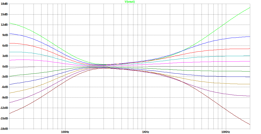
You can experiment with the frequency and boost of the bass by adjusting R6, R7, C5 and/or R8, R9, C6. With the values suggested, the response at 10% intervals looks like this:
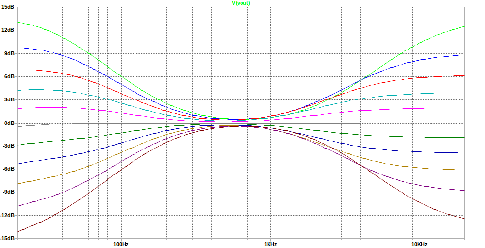
Bass response calculation has two frequency components:
- fb0 - the frequency where boost or cut starts to level out
1 / ( 2π × C6 × VR1 ) , e.g.,
1 / ( 2π × 47nF × 100k ) = 34Hz - fb3 - the ±3dB frequency
1 / ( 2π × C6 × R8 ) , e.g.,
1 / ( 2π × 47nF × 22k ) = 154Hz
Treble response is calculated as one frequency component:
ft
1 / ( 2π × C5 × R10 ) , e.g.,
1 / ( 2π × 1nF × 22k ) = 7.2kHz
It's not that simple though because the interactions with the other controls - i.e. changing the bass actually affects the treble, as well as the treble control setting (series resistance) changing the 3dB point. To see the real response, running a SPICE simulation is best.
Note that there will be a fair pop and speaker movement at power on whilst the capacitors charge. This is normal and difficult to avoid without a muting circuit. Many modern amplifiers chip amps do have mute pins which can be timed to enable after about half a second so when powering both this circuit and the amplifier at the same time, you would avoid the pop by having the amplifier unmute itself around half a second after.
Below is a list of components for a mono bass/treble tone control:
| # | Type | Quantity |
|---|---|---|
| U1 | TL072 | 1 |
| VR1,VR2 | 100k ohm Variable Resistor / Potentiometer, Linear | 2 |
| R1,R2,R3 | 100k ohm Resistor, ¼W Metal Film, 1% | 3 |
| R4,R5,R6,R7 | 10k ohm Resistor, ¼W Metal Film, 1% | 4 |
| R8,R9,R10 | 22k ohm Resistor, ¼W Metal Film, 1% | 3 |
| R11 | 47k ohm Resistor, ¼W Metal Film, 1% | 1 |
| C1 | 1µF Capacitor, 35V+ Electrolytic | 1 |
| C2 | 2.2µF Capacitor, 25V+ Electrolytic | 1 |
| C3 | 100nF Capacitor, 50V+ Ceramic / MLCC | 1 |
| C4 | 100µF Capacitor, 35V+ Electrolytic | 1 |
| C5 | 1nF Capacitor, Polyester Film/Box | 1 |
| C6 | 47nF Capacitor, Polyester Film/Box | 1 |
| C7 | 10µF Capacitor, 25V+ Electrolytic | 1 |
| Headers | 2.54mm headers | 1 |
| Cable, connectors | ~ |
21 components are required, including the chip, excluding headers / links / wires etc.
Potentiometers and correct orientation
You should get linear (not logarithmic) potentiometers. These are usually prefixed with the letter B - i.e., B100k.
If you already have 10k potentiometers or cannot get 100k ones - you can use these instead but divide the resistor component values of R6, R7, R8, R9, and R10 by 10, (so use 1k and 2.2k) and multiple the capacitor values C5 and C6 by 10 (10nF and 470nF). This actually achieves the exact same result.
Orientation is important as you'll want both bass and treble to be boosted as you rotate clockwise. To ensure that the orientation is correct, view the potentiometer from the front with the three pins / tags at the bottom.
The left most pin (pin 1) must point towards the output of U2 (C7 via R7/R9 on the schematics above). The right most pin must be fed from the output of U1 (via R6/R8).
With the correct potentiometer type, a setting of 50% will hardly alter the original sound at all.
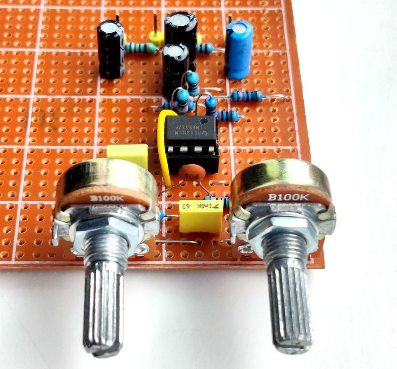
Stripboard PCB - Mono
The PCB layout below is for Stripboard / Veroboard PCB, using a standard dual opamp like the TL072 or NE5532 as examples. Stripboard is easily obtainable and whilst technically prototype board, it'll last years anyway. This version is intended to work on +9V or more (up to about +30V) and is a mono example.
I currently don't feature a custom layout PCB for mono or stereo implementation. For stereo, just duplicate the above layout twice and mount the potentiometers off the board nearby. If you wish to make a PCB, see my PCB building guide, but more time is required to design, drill, draw, etch and clean.
For the Stripboard layout, this is easy to build. All you need is a soldering iron, solder, small side cutters, the Stripboard and the components. Ideally, have some desoldering braid too to correct mistakes, and a stripboard cutter to make the track cuts where needed (a small drill bit or some careful knife work would work too though). Build time is around an hour or two.
Being stripboard, the layout is constrained and as a result it's fairly big at 5.7 x 5 cm, but perhaps still small enough to place in many projects. A custom PCB using a DIP style opamp would be smaller, but perhaps not that much smaller due to the pots.
This circuit is intended to work with through hole 8-pin DIP operational amplifiers, such as the TL072, NE5532 or 4558. They will all need voltages of ideally +12V or higher though or they will clip. If you need a circuit that will operate off 5V, you have to go for a rail-to-rail opamp like the LMV358, but you could still use the Stripboard layout if you buy an 8-pin SOIP to DIP adaptor.
Note that the potentiometers are mounted on the board. This reduces wires in your project but means you'll have to have the exact spacing on your front panel for the potentiometers. Distance between holes for mounting is about 28mm and as this is quite tight, use smaller knobs such as 15mm diameter. As the board extends a fair bit back from the front too, take care with layout constraints and consider mounting the board too so it doesn't wobble.
Alternatively, you can wire the potentiometers off the board. For a stereo version, this would be the best option as combining dual track potentiometers onto single layer Stripboard is challenging!
Below is the layout I used. Take care when replicating it.
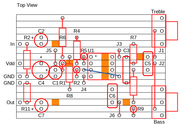
On this layout, there are nine track cuts to make, shown by orange squares. That's four track cuts where the DIP IC is, but also an additional five cuts to make.
Finally, there are seven jumper traces to install. Six of these jumper traces can be made with offcuts from the resistors or capacitors. The seventh (shown in blue) should be done with a piece of insulated bell wire.
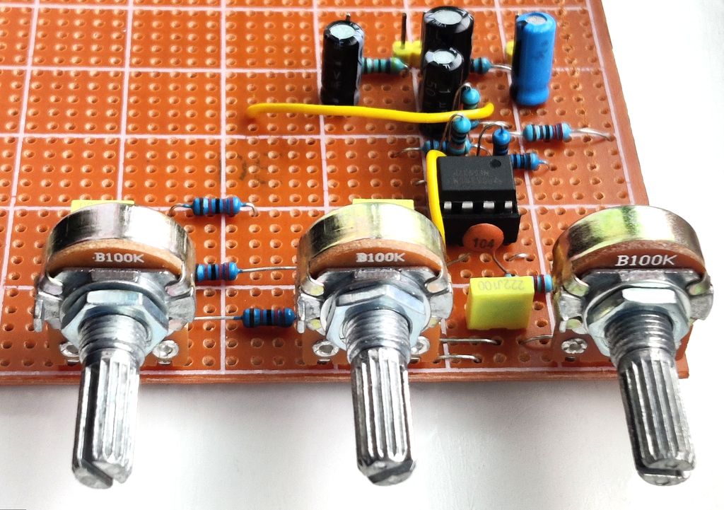
The photo above is how mine turned out. All resistors are 1% metal film. The input and output capacitors electrolytic. C5 and C6 are polyester PET capacitors. This circuit is not intended to be 'Hi-Fi', so don't buy the most expensive capacitors. Avoid ceramic though (except for C3), because their capacitance does drop when there is a DC voltage across them.
Grounding
If powering from batteries, you're unlikely to have a problem. With mains PSUs though you may get hum/buzz if the grounding layout is poor. I suggest to use a PSU where the negative is connected to earth instead of isolated so the circuit is grounded, but you are using the same PSU to also power an amplifier or other line level circuits you'll need to use a star ground.
Do research on star grounding and how to wire systems to avoid loops. It's easy to get it wrong and can sometimes need some trial and error to find the best set up.
You may also get buzzing as you adjust the controls by touching the potentiometer shafts or body. This can be solved by connecting their outer shell to ground. This shouldn't be an issue if they are mounted to a metal case though and that case is grounded. Plastic knobs also help avoid this.
Single supply tone control with middle control
Whilst most tone controls are satisfactory with just a bass and treble control, there are systems and circuits out there that also incorporate a mid (middle) control.
The Baxandall design can accommodate this too by adding a third set of components that are a kind of hybrid of the bass and treble control, forming a band-pass filter around the middle control potentiometer.
The design below uses components similar to the above with the centre frequency aimed for around 640Hz (a more sensible middle compared to 1kHz) and therefore the middle control has been aimed for that setting too.
There is a challenge with this circuit though and that's the interactions between the controls. In particular, the treble control is quite severely impacted by the setting of the mid-control. The middle boost for example cuts the boost of the treble control. To reduce the impact, I've opted for a greater overall cut / boost for the treble control. I've looked and simulated other circuits online and they all suffer from the same problem.
It adds simplicity to only build two controls as if you want to boost mid, boost the volume and cut treble/bass equally. Still, it adds more versatility to sound control, and you may find a combination such as boost, cut, and boost to get the sound you want.
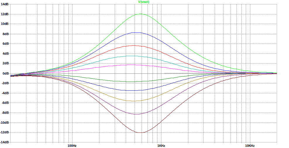
The below simulation shows the response with the mid-control centred (50%) and the bass and treble controls moved in 10% increments:
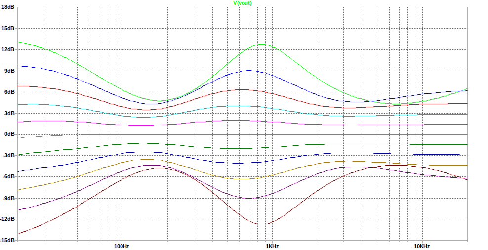
The below simulation shows the response with all controls moved in 10% increments. You can see the impact on treble:
Finally, this shows the tone with the middle control moved in 10% increments, and bass + treble left at the centre (50%):
Below is a list of components for a mono bass, mid + treble tone control:
| # | Type | Quantity |
|---|---|---|
| U1 | TL072 | 1 |
| VR1,VR2,VR3 | 100k ohm Variable Resistor / Potentiometer, Linear | 3 |
| R1,R2,R3 | 100k ohm Resistor, ¼W Metal Film, 1% | 3 |
| R4,R5 | 10k ohm Resistor, ¼W Metal Film, 1% | 2 |
| R6,R7 | 2.2k ohm Resistor, ¼W Metal Film, 1% | 2 |
| R8,R9,R10 | 22k ohm Resistor, ¼W Metal Film, 1% | 3 |
| R11 | 47k ohm Resistor, ¼W Metal Film, 1% | 1 |
| R12,R13 | 5.6k ohm Resistor, ¼W Metal Film, 1% | 2 |
| C1 | 1µF Capacitor, 35V+ Electrolytic | 1 |
| C2 | 2.2µF Capacitor, 25V+ Electrolytic | 1 |
| C3 | 100nF Capacitor, 50V+ Ceramic / MLCC | 1 |
| C4 | 100µF Capacitor, 35V+ Electrolytic | 1 |
| C5 | 2.2nF Capacitor, Polyester Film/Box | 1 |
| C6 | 47nF Capacitor, Polyester Film/Box | 1 |
| C7 | 10µF Capacitor, 25V+ Electrolytic | 1 |
| C8,C9 | 10nF Capacitor, Polyester Film/Box | 2 |
| Headers | 2.54mm headers | 1 |
| Cable, connectors | ~ |
26 components are required, including the chip, excluding headers / links / wires etc.
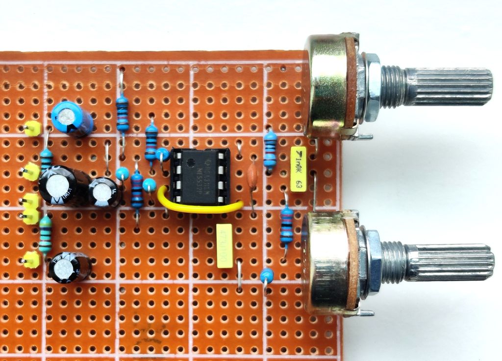
Stripboard PCB - Mono
It's fairly easy to modify the Stripboard layout from above to incorporate a mid-control, so here's my take on it:
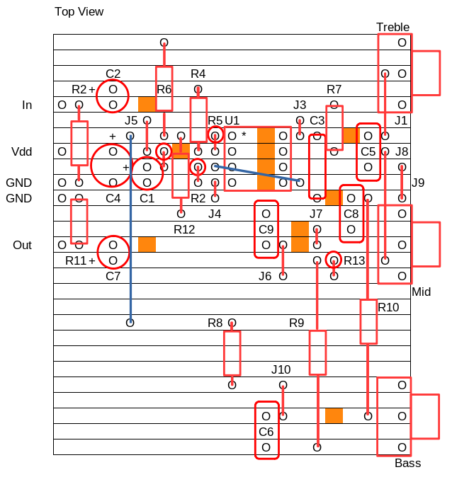
The layout is designed so that the distance between each control is the same for front panel mounting. If your controls are to be mounted off the board though, you can compact the layout a little more. The size as shown is about 5.7 x 7.3 cm.
For testing, I built this too (by modifying the bass/mid version). It took about an hour to modify as a few resistors and capacitors needed altering plus more jumpers (there are now ten on board, plus two wires), track cuts (now twelve are required in total) and components.
References that helped and further reading:
- ESP - Equalisers, The Various Types And How They Work
- ESP - Designing With Opamps - Part 2
- ESP Project 94 - Universal Preamp / Mixer
- ESP Project 97 - Hi-Fi Tone-Control Preamplifier
- Stack Exchange Electronics - Explanation of 3 Tone Control Circuit
- Electronic Engineering Dictionary - 3-Band Active Tone Control
- Tataylino.com - 3 band tone control design
- Learnabout Electronics - Amplifier Controls
- My bass boost article