
Bass Boost circuits
This article is dedicated to methods of boosting bass for systems where it's desired by adding circuits before the amplifier.
Bass is a troublesome frequency, but we feel dissatisfied when listening to a setup that just doesn't have enough bass.
I've now setup and used a number of bass boost circuits, and they can lift the low-end for systems which use small speakers (i.e., portable), or systems which have reasonable sized bookshelf speakers, but response below 100Hz still needs a little help, especially when listening at low volumes.
Speakers are constrained by Hofmann's Iron Law - Small cabinet, High efficiency, Bass response - pick any two!
For small/miniature speakers, especially portable ones, physics plays a restriction. The speakers in a small box/cabinet with a small baffle are going to struggle reproducing frequencies efficiently below 200Hz and drop quite rapidly after 100Hz. Remembering that small, portable, speakers need to have some efficiency so they can respond with low, battery powered amplifiers. Otherwise, at their size, they'd overheat with big amplifiers.
For small 'hi-fi' speakers, i.e., bookshelf ported or non-ported speakers with 4 to 5 inch drivers, these can do quite well, but response is often quoted down to 70Hz only and I still prefer a lift of bass below 100Hz, especially when I'm listening at low volumes such as when I'm working and listening to the radio. In these cases, the normal tone controls don't work so well as the bass adjustment can be too 'boomy' as it's lifting too much above 100Hz.
Bigger speakers are fine, and my main system running floor stander speakers does not have a bass boost. Setups with subwoofers also do not need bass boost.
But for other setups, here, I've presented some solutions to boost the frequencies required. It's almost like a loudness filter, fresh out of the 80's! But they do not boost treble.
Note that boosting bass has a downside though - the power amplifier will require more power to give the speaker higher voltages at these frequencies. This will reduce your overall volume, causing distortion to kick in a sooner once you whack up the volume.
Even if your amplifier is powerful enough, also bear in mind that increased bass will cause more speaker excursion and it may reach its limits sooner, especially if it's a ported speaker and your boosting below the ports tuned frequency.
I also don't recommend these for hi-fi systems connected to vinyl/phono record players. The bass boost will amplify the troublesome rumble frequencies (below 20 Hz), causing distortion and dynamic range to suffer.
So really these circuits are more suited to improving sound quality when you're listening to music in a hotel room (quietly!), improving the sound of many TV or radio speakers, rather than partying with friends.
Ultra-simple - passive bass 'boost'
This circuit isn't a true bass boost (see active ones below), it's a passive circuit which actually cuts the frequencies except the bass, leaving the bass close to the original input level.
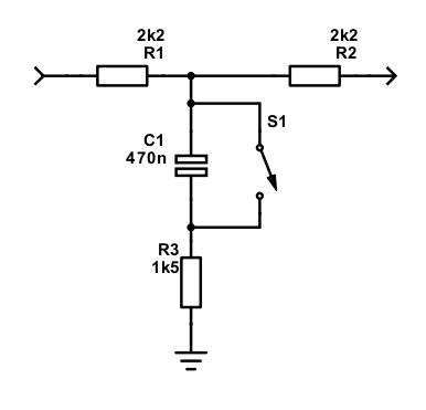
It's a dead simple circuit (showing one channel only), with a benefit of being symmetrical so it doesn't matter which port is in/out.
My example has a loss of 8dB for frequencies above 1kHz, about 2.6dB loss around 100Hz, and a minimal loss (0.6dB) for bass around 40Hz or lower. Below is the simulation output:

How it works is higher frequencies can travel through the capacitor, and that portion of the higher frequency output goes to ground through R3. Larger frequencies begin to look like DC to the capacitor, and so are blocked from being bridged to ground, attenuated only by R1/R2.
The switch can be used to short the capacitor, therefore making all frequencies go through R3 - removing the bass boost, but still giving the same cut in frequencies. You could bypass the circuit altogether as an alternative, but this would give a surprise sudden boost in overall volume.
In my scenario, the quite dramatic cut in sound level is noticeable once in use, it is ⅖ the input level after all. Fortunately, the power amplifier I use combined with the TV headphone output has enough power though to reach comfortable listen volumes (and a bit more). The bass is noticeably warmer, but being a passive circuit, it has lifted a little too much above 100Hz, but the result still sounds better with than without.
This is the problem with passive circuits - the overall cut may be unacceptable, and also the impedance of the input and output can affect the result.
If less 'boost' is required, you can increase R3 to a larger value, so less overall level goes to ground.
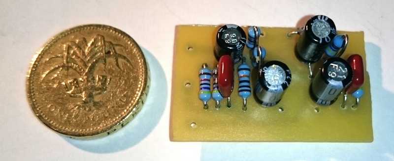
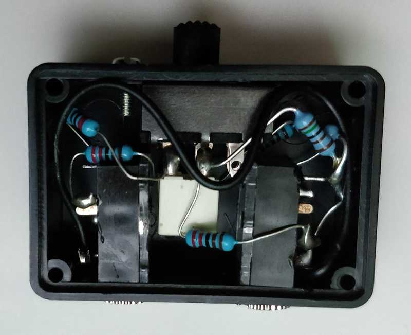
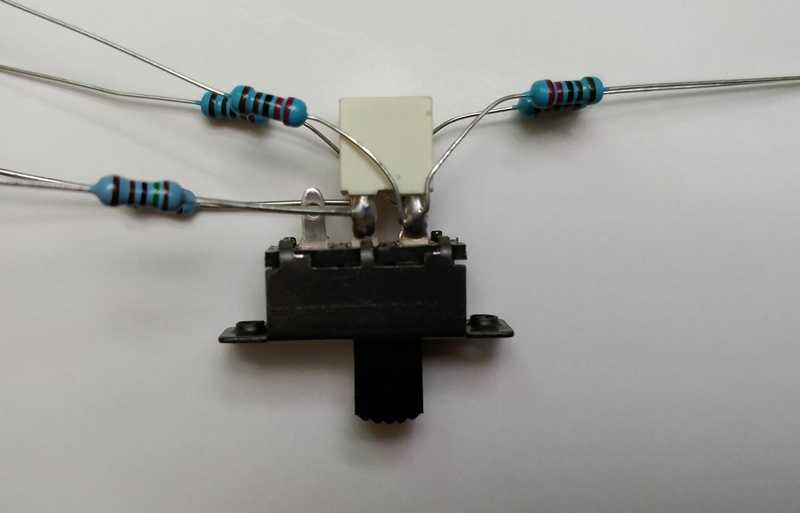
Given the simplicity of the circuit, it may not even need a PCB. I managed to squeeze six resistors, two capacitors, two 3.5mm jacks, and a slide switch to defeat the 'boost', all in a small 4 x 3 x 2cm project box and wired it point-to-point.
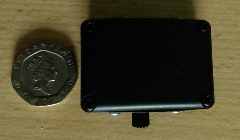
I used this on my small TV in the second bedroom which is hooked up to a small PAM8610 amplifier (10W+10W) and some cheap Eltax speakers from 2009. It's tiny, hangs round the back of the TV and since it's un-powered, only two 3.5mm jack cables go to it.
Passive bass boost box
With cover off
Initial soldering of components
Active boost
Here are some better versions. Unlike the passive circuit, they actually do boost the bass.
The first version is a simple non-inverting boost that would be ideal for fitting into diy or other amplifiers that are driving relatively small bookshelf speakers.
It relies on a single op-amp (per channel), and this must be driven from a split power supply. Split power supplies have a positive rail, a negative rail, and a ground line (0V). Typically, they are +/-12V or +/-15V. Op-amps need split supplies to allow them to output an AC signal, where the AC audio signal goes positive and negative to the ground reference.
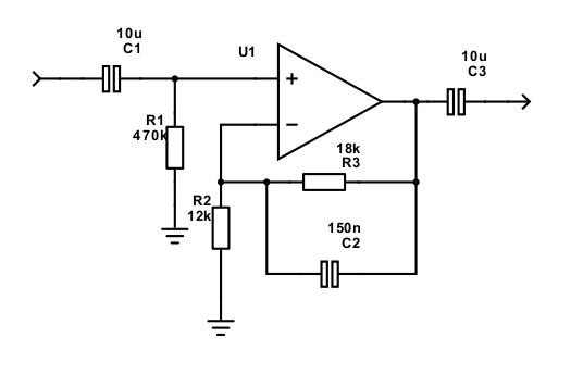
The above circuit shows just one channel for simplicity. It also does not show the power supply connections - these go direct to the op-amps power supply pins and should be bypassed with a 100µF capacitors to ground, and a 100nF capacitor directly across the positive and negative rails. Put these as close as possible to the op-amp supply pins (pins 4 and 8 for a dual op-amp).
With the values shown, you'll get an 6dB boost at 50Hz, rising to 7.6dB at 20Hz. At 100Hz, it's 3.5dB, leveling out around 250Hz.
The choice of op-amp is not critical. If you're building a stereo version, go for a dual op-amp for convenience. Typical parts are TL072 and NE5532.

I built and used a similar response in my bedroom amplifier, which is connected to a radio and a set of small bookshelf speakers. The extra low frequency lift was kept subtle and works well. For me, it's a cheaper and more convenient option than adding a subwoofer.
Single supply non-inverting version
The above circuit is simple and recommended if you have a split rail power supply available, but typically the kind of systems that need a bass boost are small systems, running off +12V, +5V or just batteries where the negative terminal is ground, zero volts.
The next circuit supports just that and operates on a single 5V power supply for convenience and can even operate down to 3V if you use an LMV358, or it will work with +9V to +24V with standard dual opamps like 4558, TL072, NE5532 and similar. It will boost the input signal for lower frequencies so that your power amplifier receives a larger signal for these frequencies, and subsequently your speakers.
The goal for this version was to make a very small, battery operated circuit which you can squeeze into small speakers and improve the bass response.
As a reminder, op amp circuits are simpler to build with a split power supply. In my hi-fi systems I use +15V, -15V and a ground 0V. Split supplies are required for an AC signal to go positive and negative to the ground.
But for battery operated / single supply circuits, we can do either of these options:
- Use two batteries in series, with the 0V line taken from where the negative terminal of the first battery meets the positive terminal of the second. This has a disadvantage of also requiring a split power supply when powering off the mains and makes operating off, say, a USB port difficult.
- Use a splitter - a simple voltage divider (such as Project 43 on sound-au.com) can split the battery or USB port supplying a half voltage for the ground. This becomes a problem when the source supplies the signal and power ground though - such as a laptop supplying USB ground and audio ground via the headphones port. Suddenly the headphone port gets 2.5V - not ideal!
- Use a splitter to offset the input signal to the op-amp, creating a virtual ground reference. The circuit below does that. It offsets the signal by adding half the voltage (i.e., 2.5V for 5V) to the AC signal. This allows the AC signal to go negative up to -2.5V and positive up to 2.5V.
The third option is used here. This allows me to connect any battery, USB power source or single supply PSU without a worry.
There are some disadvantages to using this method - so for hi-fi, I recommend split supplies, but this circuit is not really hi-fi!
- You need to use some more components. For split rail operation you can reduce the component count.
- Less stability - fluctuations on the power supply, hiss and hum can be injected into the input signal.
- Low frequency cut-off - there are high pass filters in the circuit (to block DC), and these therefore have a -3db cut-off point where low frequencies start to fall off (at -3dB, the signal is halved). For really small speakers though, we can use this to our advantage. This is because we can cut frequencies below around 30Hz, since those kinds of speakers are never going to get there anyway, so why waste power!
Op-amp choice
If this circuit is built with a +9V or higher single supply, the op-amp itself is not critical as it can boost without clipping. NE5532, TL072, or even a humble 4558 will work OK if you have +12V available.
With only a single supply of 5V or lower though, these typical op-amps cannot work as they can only reach 2V to 3V of the supply voltage. The 2.5V DC offset is already within the limits and won't allow an up to +/- 1V AC signal to run through it.
We need something more modern. Rail-to-rail op amp exist and many of these will suit the requirements. I went for the LMV358 (not to be confused with the LM358) as it is one of the cheaper rail-to-rail op-amps. This is a dual op-amp but comes in an 8SOIC package (or even smaller - but these are really difficult to solder for DIY!). Standard DIP rail-to-rail are rare, but you can buy SOIC to DIP adaptors cheaply and I did just that to prototype this circuit on a breadboard, and I brought 10 of them for experiments, spares, and potential future use.
The small size has an advantage - with a few other surface mount and back soldered components, the PCB can be made very small! See inverting version below. I'm quite happy with the LMV358 choice - however be aware that this chip has a maximum supply of 5.5V, so the application is limited to USB power or 3x 1.5V batteries. For my speakers, I'm either using a PAM8403 amplifier which has the same voltage restriction, or a bridged TDA2822 which shouldn't take more than 6V single rail, so I didn't mind.
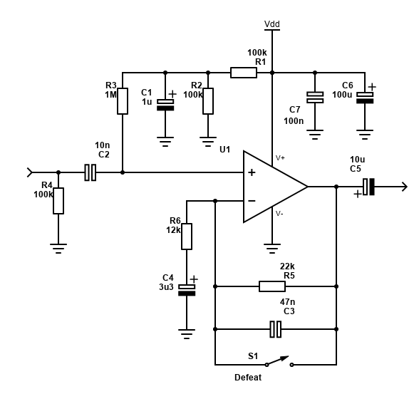
Non-inverting - bass boost for small speakers
This is the circuit that I use in my PAM8403 mini speakers. It provides a fair boost to bass and makes the speakers sound better instead of an overpowered mid-range sound. This is the circuit I recommend you use as it works well.
Circuit operation
So, how does it work? Here are some pointers with a single supply voltage of 5V:
- R1 and R2 make a voltage divider to get the 2.5V DC offset from 5V. This is applied to the AC signal after R3. The suggestion is 100k (for upwards of 5V), or 33K (for down to 3V) for battery operated devices to reduce power consumption. Lower values for R1/R2 reduce hiss and improve stability at the expense of power consumption. The goal here is battery operation and USB operation, so lower consumption is better for longer life and more volume on the amp when required!
- C1 is to reduce hum on the DC output of the divider. 180nF or upwards will work effectively. Don't go too large otherwise the time to stabilise when the circuit is switched on will increase. I used 1µF in mine, removing any noise above 0.2Hz.
- R3 is a 1M Ω resistor to match the high input impedance of the op-amp. It's needed so that C1 does not remove the audio signal.
- Capacitor C2 acts as a DC blocker, so our 2.5V offset applied to the signal does not flow back to the source, where it may do damage. It is also a high pass filter used to cut frequencies from 160Hz and lower. The value of 10n gives me roll-off after 63Hz when combined with the boost, so my boost is not boosting frequencies below this frequency as much, since small speakers are very unable to produce those frequencies anyway. If you do not want this though, make C2 100n or higher.
- C3 sets the boost frequency. At low frequencies, C3 blocks the signal, forcing low frequencies to go via R5 instead. This is the part that makes the op-amp boost the bass. If you want to switch on/off the boost, you can add a 'defeat' switch to short over C3.
- R5 and R6 set the bass gain. With 12k and 22k, the maximum gain is 2.83 (9dB). That's calculated as 1+(22/12) = 2.83. In dB - that's 20*log(2.83) = 9.
- C4 is another DC blocker. It also forms a high pass filter with the impedance of R6. I used 3.3µF to give a comfortable cut-off of 4Hz.
- C5 blocks DC from output signal (this would have a 2.5V DC offset on a 5V PSU). Again, it forms a high pass filter with the impedance of the amplifier this circuit is connected to. Make C5 large enough to cope with a variety of amplifier impedances. 1µF with a 10k amp impedance (fairly typical) gives a cut at 15Hz.
- R4 gives our circuit a lower input impedance, which is required for some sources, particularly if they were designed to drive headphones.
- Finally, power supply bypass capacitors C7 (100nF ceramic as close to the IC as possible) and C6 (polarised electrolytic) are needed for stability.
You can experiment with the frequency and boost of the bass by adjusting C3 and R5. With 47nF and 22k, the response will look like this:

That's quite an aggressive bass boost, so adjust as needed. Reducing R5 to 12k will take it to 2x gain for example.
Note the signal starts to cut again below 63Hz. If this isn't wanted, increase C2 to 100nF or higher. Here is what the response will look like with 100n input capacitor.

The above circuit is for one signal. To build a stereo version, duplicate everything except for R1, R2 and C1 - the creation of the 2.5V offset can be shared for both channels.
Remember, though not shown, bypass capacitors are needed on the supply input to ground. Add a 100nF and a 100µF capacitor close to the op-amps pins 4 and 8 (smaller capacitor being the closest to the op-amp).
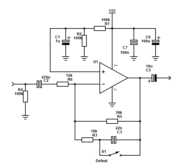
Single supply Inverting version
The schematic below shows the circuit for one channel. It is in an inverting configuration - these give us the ability to cut as well as gain (non-inverting can only gain), however if you are intending to combine this bass boost circuit with other speakers or a subwoofer, you will be out-of-phase with these, which can cancel out sound waves.
Therefore, this circuit is intended for use with speakers on their own or followed with a simple inverting buffer following this will put the phase back as required.
It's benefit over the non-inverting version above is two components less per channel, and for single supply operation, inverting configurations are typically more stable. The other benefit is being able to attenuate the signal too - allowing you to build a cross between cutting the non-bass frequencies and boosting the bass ones in the case where you want some serious bass lift without causing the op-amp to clip.
How does the inverting one work? Here are some pointers:
- R1 and R2 make a voltage divider to get the 2.5V DC offset which is applied to the AC signal after R3. The suggestion is 100k (for upwards of 5V), or 33K (for down to 3V) for battery operated devices to reduce power consumption. Lower values for R1/R2 reduce hiss and improve stability at the expense of power consumption. Once again, the goal here is battery operation and USB operation, so lower consumption is better for longer life and more volume on the amp when required! The output of the voltage divider feeds into the positive input of the op-amp - in a split supply, this positive pin is usually connected to ground, but here we connect it to our 2.5V virtual ground.
- C1 is to reduce hum on the DC output of the divider. 180nF or upwards will work effectively. Don't go too large otherwise the time to stabilise when the circuit is switched on will increase. I used 1µF in mine, removing any noise above 0.2Hz.
- Capacitor C2 acts as a DC blocker, so our 2.5V offset applied to the signal does not flow back to the source, where it may do damage. It is also a high pass filter used to cut frequencies from 160Hz and lower. The value of 470n gives me roll-off after 63Hz when combined with the boost, so my boost is not boosting frequencies below this frequency as much, since small speakers are very unable to produce those frequencies anyway. If you do not need this though, make C2 2µF or higher.
- C3 sets the boost frequency. At low frequencies, C3 blocks the signal, forcing low frequencies to go via R5 instead. This is the part that makes the op-amp boost the bass. If you want to switch on/off the boost, you can add a 'defeat' switch to short over C3.
- The normal gain I made close to unity - this is R5 and R3 divided by R6. As the 39k and 18k resistors both contribute to the non-bass frequency gain, resistors in parallel are calculated as 1 / ((1/39) + (1/18)) - which gives 12.3k. Therefore, normal gain is around 1.025.
- R6 and R5 set the bass gain. With 39k and 12k, the maximum gain is 3.25 (5.2dB), but it does not quite reach this due to C2 which cuts some of the lower frequency, as shown in the frequency response graph below.
- C5 blocks DC from output signal (this has a 2.5V DC offset on a 5V PSU). Again, it forms a high pass filter with the impedance of the amplifier this circuit is connected to. Make C5 large enough to cope with a variety of amplifier impedances. 1µF with a 10k amp impedance (fairly typical) gives a cut at 15Hz.
- R4 gives our circuit a lower input impedance, which is required for some sources, particularly if they were designed to drive headphones.
- Finally, like the non-inverting version and any opamp circuit, power supply bypass capacitors C7 (100nF ceramic as close to the IC as possible) and C6 (polarised electrolytic) are needed for stability.
The frequency response I kept similar to the inverting version above but using standard capacitors and resistors that are easy to obtain. Feel free though to adjust the resistors and capacitors in use to the frequency response you prefer.

Update: The simulator at partsim.com seems very unreliable now. I've built a model in LTSpice XVII which you can download here and feel free to experiment with changing the values and running the simulation.
Note that there will be a fair pop and speaker movement at power on whilst the capacitors charge. This is normal and difficult to avoid without a muting circuit. Many amplifiers chips do have mute pins which can be timed to enable after about half a second so when powering both this circuit and the amplifier at the same time, you would avoid the pop by having the amplifier unmute itself around half a second after.
Inverting - Full schematic
Below is a full schematic for a stereo version and provisional values that you can start with.
I've added a switch to turn off the boost, achieved by shorting out C1. When shorting C1, you'll get a modest cut in volume which should hardly be noticeable with a 1M resistor for R3. R3 and R2 in parallel gives 44.8k giving a gain of (44.8 / 47) = 0.95. A normally closed or push to break switch would give you a button that you push in for bass boost. It needs to be double pole for stereo.
Alternatively, the bass boost can be switched off by bypassing the circuit altogether using a DPDT switch to bypass the stereo signal. The signal would change phase however, as this circuit inverts it when active.
In addition to the schematic above, you should add bypass capacitors across the op-amps negative and positive pins (pins 4 and 8). This would be a 100nF ceramic capacitor and 100µF electrolytic capacitor, shown in the full schematic below. These capacitors should be as close as possible to the op-amp pins.
This schematic also has added bypass capacitors on the 1/2 V supply - C2 is 100nF but to give better performance, C8 is added which is a 100µF electrolytic.
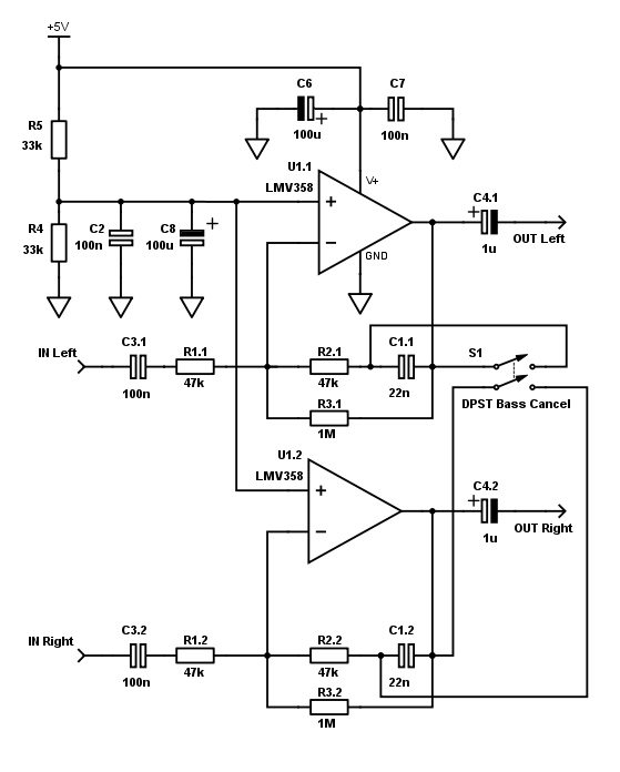
The circuit shown gives quite a lot of boost - R3.1/R3.2 is shown as 1M ohm - this gives good results but do experiment. During my tests, I found that this circuit runs better placed after a volume control. Connecting directly to the source can sometimes cause problems and I found that whilst connecting directly to TV or a portable radio was absolutely fine, connecting to the headphone out for mobile phones caused one channel not to work, and the other to be slightly distorted. This is because R4 from the basic circuit is not present.
To solve this, put this circuit after a volume control. Shown below is how I also added a low pass filter too in order to cut high frequencies and reduce the load on the source. Shown with 1k and 6.8nF capacitors, frequencies above 23kHz will be -3dB down. I however used 10nF which will be down -3dB at 16kHz - which good enough for music and TV use and I doubt my small speakers will reproduce frequencies above this anyway. You can adjust the resistor and capacitor to suit - the -3dB point is calculated with 1 / (2πRC). 820 ohms and 10nF will be another good combination - 19.4kHz -3dB point.
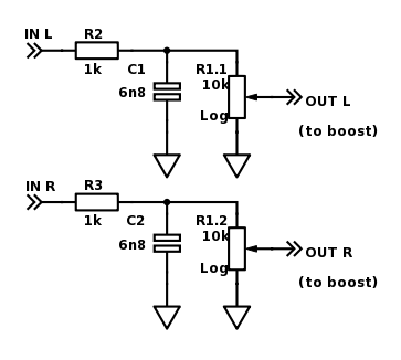
With this, connecting mobile phones to the speakers worked perfectly, with good bass boost. Alternatively, if you already have a volume control in your amplifier, you may get some success (not tested) by just putting a 10k resistor between the input and ground.
Response of the version above is shown here:

PCBs
I'm featuring two different kind of PCBs here, though I may add more if I build them. Both are stereo and both are single supply.
The first is a Stripboard / Veroboard PCB for the non-inverting bass boost using standard dual opamps like the TL072. Stripboard is easily obtainable and whilst technically prototype board, it'll last years anyway. This version is intended to work on +9V or more (up to about +30V).
The second is a custom made PCB for the inverting configuration. It is still very much possible to build at home with a few cheap tools (see my PCB building guide), but more time is required to design, drill, draw, etch and clean. This version uses a surface mount LMV358 and is very small because of that and is intended to operate off +5V.
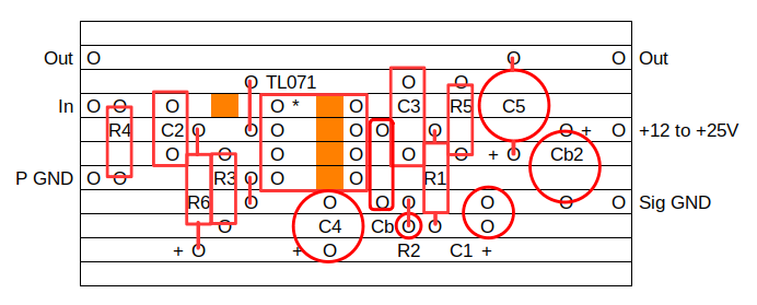
Stripboard - Stereo non-inverting
This version is probably the most accessible to hobbyists! All you need is a soldering iron, solder, small side cutters, the Stripboard and the components. Ideally have some desoldering braid too to correct mistakes, and a stripboard cutter to make the track cuts where needed (a small drill bit or some careful knife work would work too though). It took me about an hour to solder.
Being stripboard, the layout is constrained and as a result it's fairly big at 7.3 x 3.7 cm, but perhaps still small enough to place in many projects. A custom PCB using a DIP style opamp would be smaller, but perhaps not that much smaller as my layout below packs the components quite tight as uses most of the space.
This circuit is intended to work with through hole 8-pin DIP operational amplifiers, such as the TL072, NE5532 or 4558. They will all need voltages of ideally +12V or higher though or they will clip. If you need a circuit that will operate off 5V, you have to go for a rail-to-rail opamp like the LMV358, but you could still use the Stripboard layout if you buy an 8-pin SOIP to DIP adaptor.
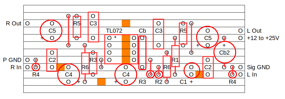
Below is the layout I used. Take care when replicating it.
On this layout, there are eight track cuts to make, shown by orange squares. That's four track cuts where the DIP IC is, but also an additional four cuts to make. One track cut is above the DIP to isolate R Out and C5 on the left side from C3, R5 and the jumper on the right side. Two track cuts on the left hand side of the board also need to be made - to the right of C2 (bottom joint) and to the right of R6 (bottom joint). There is also one track cut to make on the right hand side of the board between C1 and C2. I suggest making these track cuts before soldering as the solder may get in the way and make the cut harder to do after.
Finally, there are three jumper traces to make one to the left of R5 on the left hand side, another to the right of R5 on the right hand side, and one at the bottom left corner of the IC. These jumper traces can be made with offcuts from the resistors or capacitors.
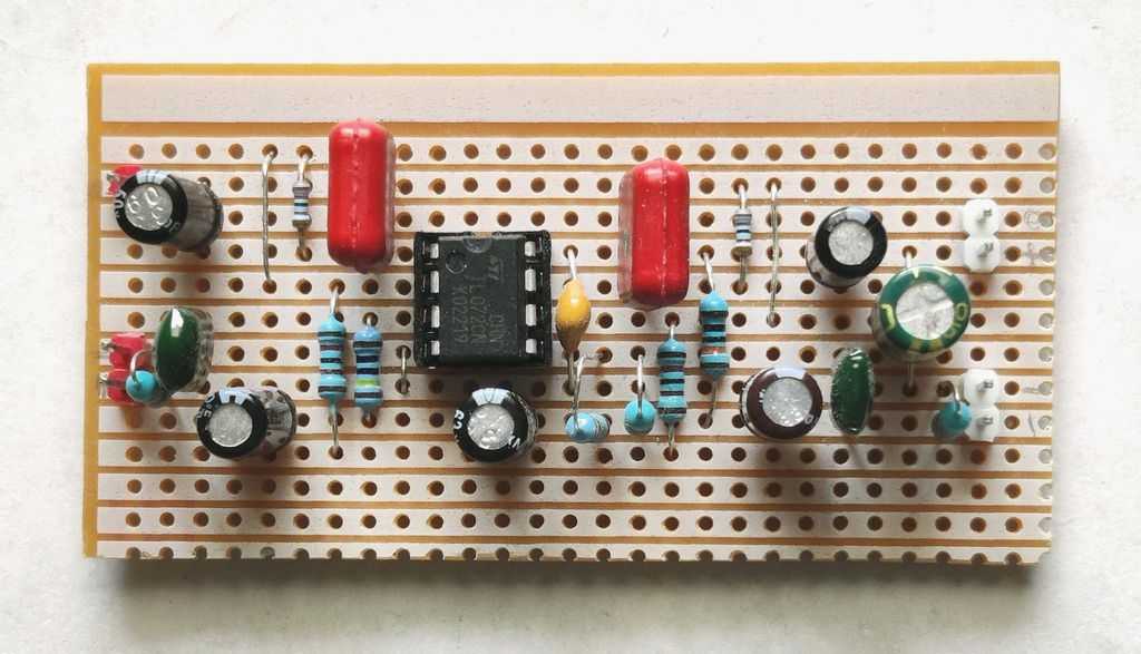
Below is how mine turned out. All resistors are 1% metal film. The input capacitors C2 are mylar polyester green-caps as these are what I had and fit nicely on three strips. C3 are polyester PET capacitors (I think, they're very old!). As said before, this circuit is not intended to be 'Hi-Fi', so don't buy the most expensive capacitors. Avoid ceramic though, because their capacitance does drop when there is a DC voltage across them. This would especially be the case for C3.
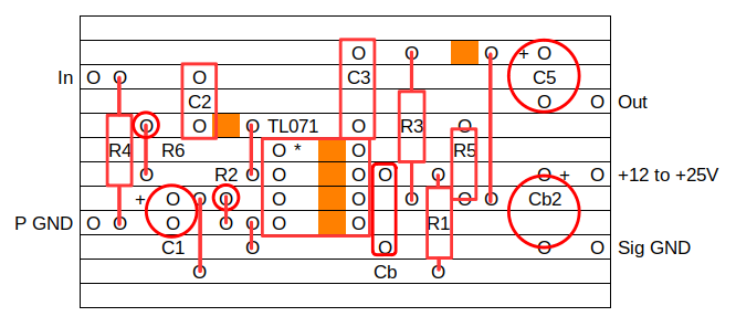
Stripboard - Mono non-inverting
Here is a mono non-inverting layout for one amplifier/speaker only. The mono board will cost less and consumes less space than the stereo version. It's easy to build too.
The same advice as the stereo version applies. You would need to pick a single op-amp for this board though, with the best being the TL071, although LF351, LM321, ua741, NE5534 and similar will also work.
Stripboard - Mono inverting
An alternative is to build the inverting version. I used this in my Bluetooth and White Noise speaker.
Below is how mine turned out, using old components, including the LF351. An MLCC was used for the 100nF bypass capacitor (the yellow one) as I had run out of standard ceramics. 22nF was used for C3, 39k for R5, 18k for R3 and 12k for R6 per my original and this works quite well for the intended speaker. Electrolytic capacitors was used for the rest.
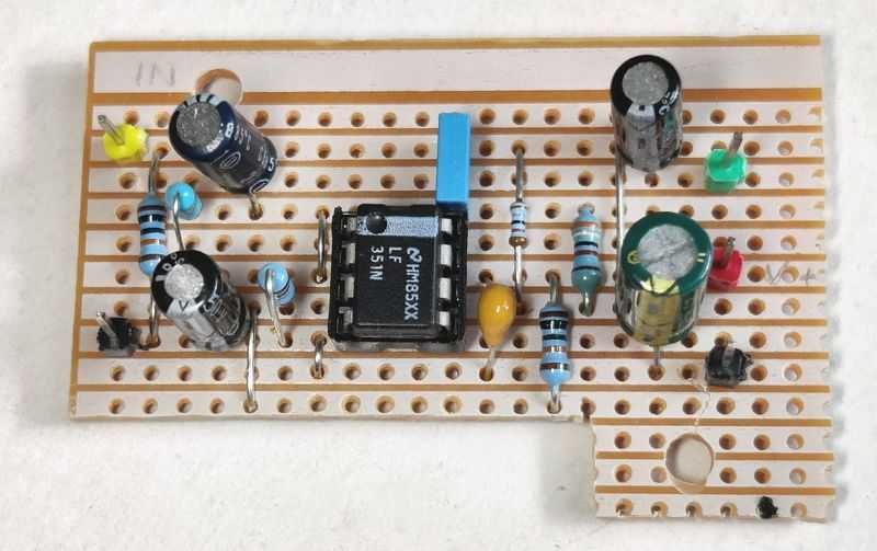
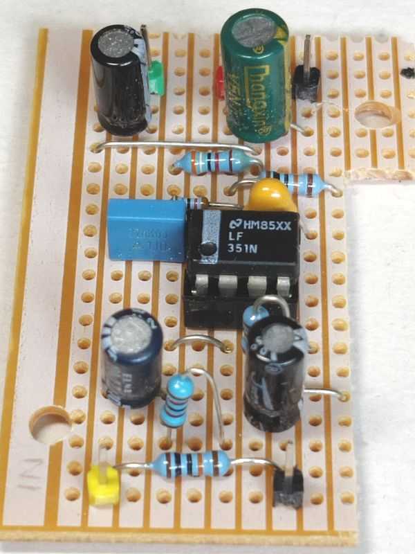
As mentioned, the inverting configuration is slightly more stable. It also ends up being a slightly smaller board, so it's the recommendation if you don't inverting the signal does not matter.
PCB - Stereo non-inverting
The boards here are manually drilled and drawn with an etch-resistant pen and etched in ferric chloride. This is cheap and easy, and actually reliable and easy to solder, but you may have the equipment to do better than this.
To see the non-inverting version, see my PAM8403 portable speakers article. Note that some components are excluded such as the DC blocking capacitors on input (since a transformer is used) and capacitors on the output too (since the PAM8403 already has them).
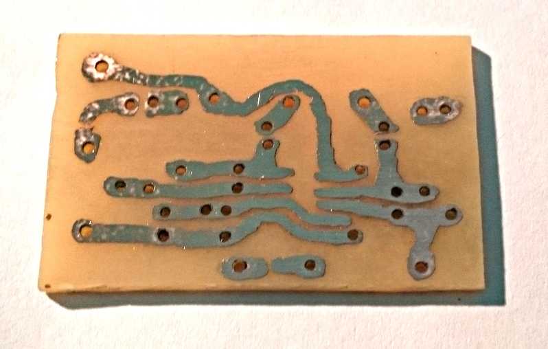
PCB - Stereo inverting
This is the ultra-small version using both the surface mount LMV358 and 100nF surface mount capacitors for the input capacitors C3 and voltage divider capacitor C2.
Below is the etched layout before soldering.
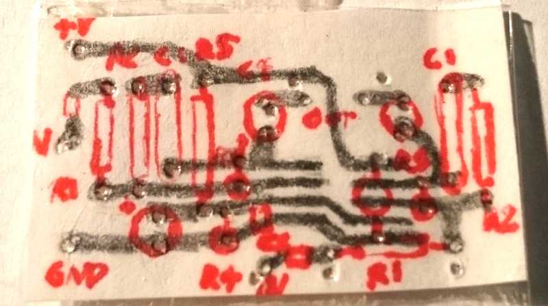
My drawn PCB version. I always like to draw the board layout with pencil on paper first so I can make corrections. I then punch holes with a compass
point so I can reverse and use this paper template as a template for drilling the board.
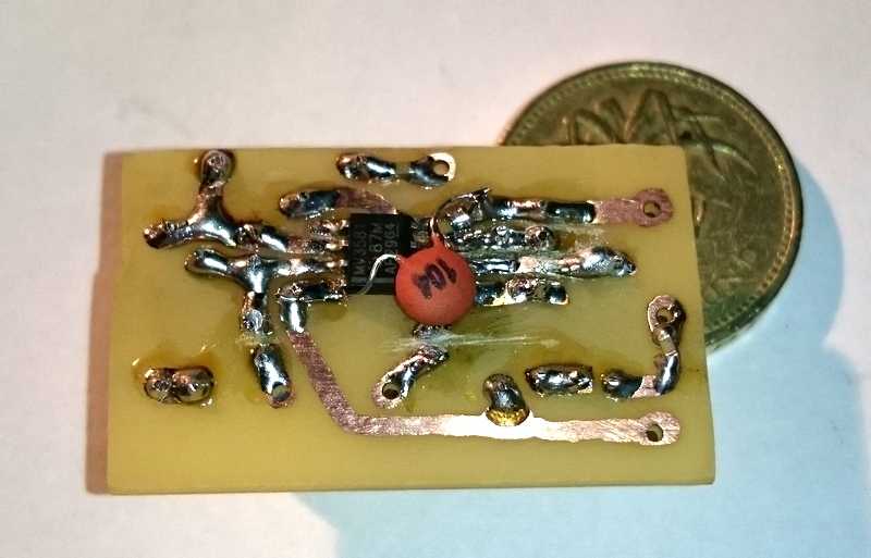
Soldered side of the board.
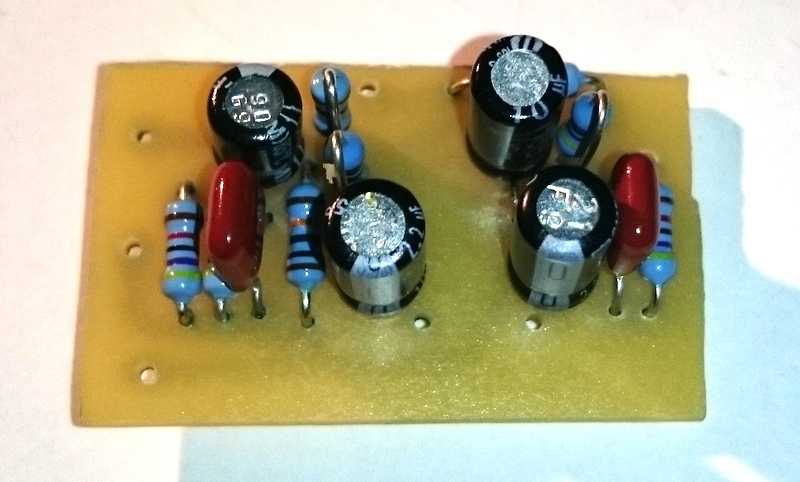
Top side of the board.
Note that my PCB design can be improved further, and you should also consider these points:
- Swap the position of R4 with the capacitor - the capacitor should be between the voltage source (the two resistors) and the drain (op-amp)
- The 100µF capacitor C6 should also be between the V in (source) and the drain (op amp) rather than the position I put it. I later soldered this to the bottom of the board close to V in and Ground, but you can include it in the design.
Note that my board used 2.2µF capacitors instead of 1µF at the outputs - these will work just as well.
With the custom PCB, SOIP op-amp, surface mount resistors and reusing the voltage divider for both stereo op amps - the result is a very small board. Light and easy to squeeze into any project, and improves the sound of my small speakers, making them sound warmer and bigger than they actually are!
I've tested this circuit on USB power and two slightly used AA batteries (giving less than 3V) - both have worked fine.
Some references that helped me with this circuit:
http://www.partsim.com
https://sound-au.com/articles/eq.htm
http://www.antonine-education.co.uk/Pages/Electronics_5/Filters/active_filters.htm
http://ta2020.huuryuu.com/usbDAC_e.html
http://electronics.stackexchange.com/questions/153911/single-supply-op-amp-audio-amplifier
http://www.swarthmore.edu/NatSci/echeeve1/Ref/SingleSupply/SingleSupply.html
http://stompville.co.uk/?p=470
https://en.wikipedia.org/wiki/Josef_Anton_Hofmann