
150W Subwoofer
Contents
Page 1 - Design
Page 2 - P3A Amplifier
Page 3 - Input filter and EQ
Page 4 - Power Supply details
Page 5 - Box Design
Page 6 - Box Construction
Page 7 - PIC Micro Control
Amplifier Power Supply
This power supply requires live mains wiring. Please do not construct it unless you are suitably qualified. Death or serious injury can result!
To power the P3A, and further power the crossover and eqauliser, a good power supply is required. Ideally, it should give a regulated +/-35V for the P3A, which can be further stepped down to power the rest of the audio circuits.
Power amplifier PSU design is pretty simple, with the minimal design being a bridge rectifier, a pair of filter caps and a transformer.
Main amplifier PSU
Above is the schematic I used for my amplifier. There a a few things to note here:
- The Fuse for a 225VA transformer is 1A for 230-250V countries, 2A for 120V and must be a slow blow type for toriodal transformers.
- The transformer itself must be 25V AC. There must be two outputs, or it must be centre-tapped. For more information on toriodal transformer wiring see here.
- The bridge rectifier must be the large 35A bolt down types for maximum efficiency.
- Although I used 33,000uF capacitors, 10,000uF caps will do. Pay attension to electrolytic capacitor polarity and note that audio grade filter caps are wasted on a subwoofer (IMO). Capacitors should be rated to 40V or greater.
- C3 and C4 MUST BE 250VAC RATED. Standard 100nF (0.1uF) polyester capacitors are of working voltage of 250 DC. If the capacitor is not rated for AC usage, it will fail (and R1 will explode). If you cannot get them, leave these out.
- R2, C4, D2 and D3 form an earth loop breaker. Without this, there is likely to be an earth loop, and audio hum as a result
As long as you are cautious and double, triple and check again and again until you are happy that everything is wired up safely, then you can test the PSU without anything connected.
Note that when testing with no load, the voltage may be around 38V. This is normal. Also, when you remove the mains power, the filter caps will still hold lots of charge. I used an old computer fan to discharge them.
Filter caps and star ground
The filter caps I used were built on their own PCB, but like those in my main amplifier, this board was not etched and constructed using a rotary tool. The layout is easy to do, and the middle section would also function as my star ground (which is essential if you are to avoid hum).
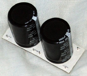
Filter capacitors on their PCB
Step down and regulation for input circuitry
The op-amps on both the P09 board and then P84 board require a regulated supply of +/-15V.
7815 and 7915 regulators are the key to providing this, but they only allow an input voltage of (+/-) 25V, or 30V at best. 35V is too much.
Thankfully, a pre-regulator can easily be built, using common and cheap TIP2955/TIP3055 transistors. Rod Elliott's P102 pre-regulator is ideal, and simple.
Construction of this is pretty easy, but choose the right resistor values. Too small and the transistors get too hot, too small and the resistor power rating raises as that gets hot too! With my 22V zener diodes, I choose a value of 680ohms which allows a cheap, standard 0.6W resistor to handle the power and keeps the transistors cool (though they still need a good heatsink).
I suggest you also use a small 10R resistor too, as loops can happen and this will break a loop with minimal loss.
The next stage of the construction is to use the regulators, as the voltage is now down to about 24 volts.
Rod's Original Power supply for pre-amplifiers is what I used here. This is the P05 version, not the updated P05A version that has better noise figures. You could build either, but I had the 7815/7915 already so I used those.
Again the regulators need to be heatsinked. If they are not, they will overheat. I would also recommend using the protection diodes and the bypass (100nF) capacitors are essential (and must be close to the regulator leads). Also note the pinouts for the 7815 are different from the 7915 and I think the same applies to the 317/337.
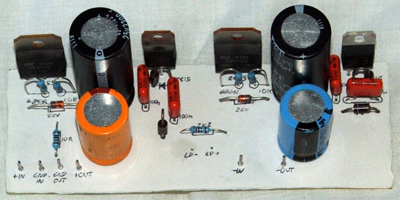
My PCB for the combined P102 and P05 projects
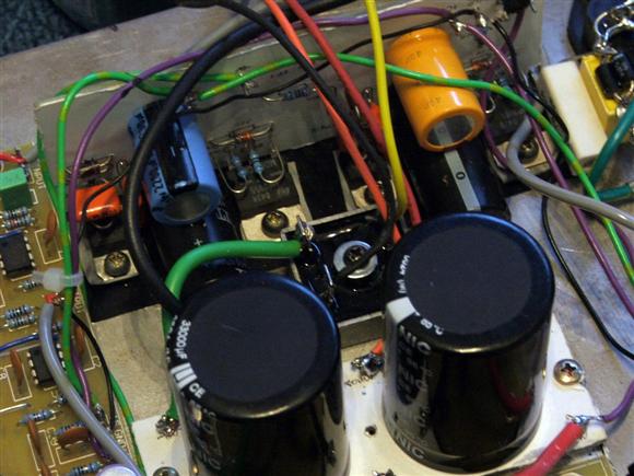
Regulator mounted and wired, and PSU overview (you can see the filter caps
and the bridge rectifier mounted)
When mounting these devices - every one of their tabs is connected to a different part of the circuit. This means that when sharing the same heatsink, they must be isolated using mica washers or sil-pads. Bushes must also be used otherwise the screw would make an effective short, and must never be allowed to do so. Choose the TO220 type and once mounted, use a multimeter to ensure that there is not short from the device tab to the heatsink. This is important!