
150W Subwoofer
Contents
Page 1 - Design
Page 2 - P3A Amplifier
Page 3 - Input filter and EQ
Page 4 - Power Supply details
Page 5 - Box Design
Page 6 - Box Construction
Page 7 - PIC Micro Control
Removing high frequencies and controlling low frequencies
For this subwoofer to work properly, I would need to remove all frequencies except for the low ones.
Most main speakers are capable of reproducing frequencies above 100Hz with enough volume. Frequencies above 100Hz also become easier for the listener to hear where the frequencies are coming from.
Since for most system the subwoofer is in a discrete place, it is not desired for the listener to realise it is there, and with it reproducing higher frequencies, they certainly can realise the subwoofer is quite some distance from the main system.
I opted for a crossover frequency of 100Hz (well 109Hz). Even accurate active crossovers will slowly fall-off after this frequency meaning that frequencies as high as 140-150Hz can still be heard through the subwoofer, but at less volume. In a way, this kind of compliments the main speakers though :)
The following diagram is from Rod Elliotts' Linkwitz-Riley Crossover page and shows how the audio level falls at the crossover frequency.
Frequency Response of 3-Way Linkwitz-Riley Crossover Network
The P09 crossover is the choice I made for my subwoofer project. For my needs, it would only need to be a mono, low pass filter. This would require only two dual op-amps and a few capacitors and resistors.
For reference, below is a modified version of the P09 crossover that consists of just one mono channel and also has the output buffer merged with it...
P09 modified for subwoofer use
Basically, everything is the same, except the fact that the high pass section has been removed and there is only one channel. The bypassing rules still apply, that is one 100nF (50V) ceramic capacitor bypassing each op-amp from +Ve to -Ve, so for the schematic above, two in total. One 100uF bypassing the +Ve and -Ve supply rails is also necessary too.
You may have noticed the input too. Two 33k resistors allow you to mix the information from both the left and right channels if you use a stereo input. For mono, just connect one of the input jacks. I suggest you use two jacks even if you have a mono input for flexibility. The output buffer from the P09 has a gain of 2 which can make up for losses in these resistors.
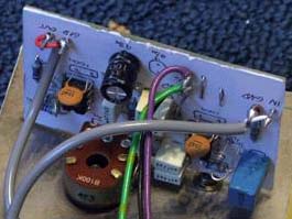
My completed P09 mono crossover board
For my design, I had a lot of 470nF capacitors spare, and needing 6 in total, this gave me (with 2.2 k Ohm resistors) a crossover frequency of 109Hz. I used the ESP Linkwitz-Riley crossover software calculator to find this as it allows preferred values. To get 100Hz exactly I would need to use 2.39 k Ohm resistors, but seeing as 2.2k is far more common, I'll live with that ;)
8-band equaliser
Let's face it, nobody has the ideal listening room (do they?). I don't. EQ is a bit of a no no for purists, but for a subwoofer (and the non-purist), it can really really work well.
Rod's 8-band equaliser allows control over frequencies at 20Hz, 25Hz, 32Hz, 40Hz, 50Hz, 63Hz, 80Hz and 100Hz (for smaller subs it can be modified to work up to 125Hz too, with the removal of 20Hz...
I kept mine at the original configuration, and it is great for those adjustments when a room has plenty of peaks, dips and resonances of bass frequencies.
Be warned though, the P84 is quite complex, and there is a lot of components involved. I certainly did not want to design my own PCB, so I brought Rod's.
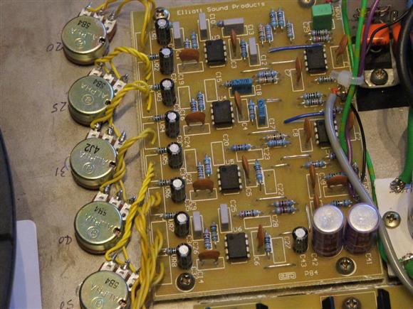
Photo of the completed P84 board, pretty smart :)
You can get small rotary pots to fit the board, but they are not as cheap as the standard "mini" versions.
There was a slight problem I came across, that most readers might not. The P84 requires some capacitors, which are in the E12 range, but hard to get in the UK for some reason, specifically 39nF and 82nF.
The best I could find was either massive, expensive high voltage capacitors of this value (not going to fit the board!) or really tiny surfacr mount devices (SMD).
I decided the best option was to go with the SMD capacitors. There tolerance is awful, but good enough I suspect. I ordered over twice as many as I would need as they are cheap, and easy to damage or lose.
Below is a picture of my handywork, sorry it is not clear (low light). Each SMD component is just 2mm in length, which is too far off the spacing on the PCB.
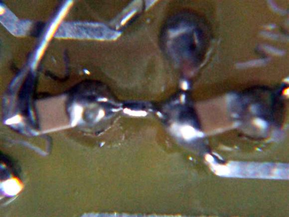
My SMD handywork
You can see that in order to cross the track running between the capacitor spacing, I had to solder the SMD to one pad, then jump the middle track with a chopped component lead, using blu-tack to carefully solder that in place and complete the link. I don't know whether I am the first person to have done this, but it does actually work, and the results are good. If you can get normal capacitors though, I certainly recommend that you do!
After the P84 equaliser, the signal then continues straight to the P3A amplifier, and that completes the input filtering.