
My 5-channel power amplifier with bi-amplified main stereo.
I suggest reading about the rebuild first. Information below is for reference purposes.
Contents
Page 1 - Idea and circuit choices
Page 2 - P3A Amplifiers
Page 3 - Crossover and Surround Channel Amps
Page 4 - Power Supply details
Page 5 - Testing
Page 6 - Improvements
Construction stages - The Power Supply
So what on earth is used to power all these amplifiers?
Power
I decided the correct transformer for my needs would be a 500VA design. Adding up the projected RMS total output of all amps gives 4*60 = 240W for all P3A's and 3*68 = 204W assuming I use an LM3886 for the centre channel.
Thats a total of 444W (all the 4's). Add the odd few watts for the crossover and that doesn't leave much headroom.
Actually it is plenty. Only two amplifiers out of those 7 are going to work near they capacities at high volume - that would be the two P3A's powering the front woofers. Output of the other two P3A's are in frequencies above 2.8kHz and therefore will be very small in comparison - 5W would be a good guess when the other P3A's are working at their hardest.
Rear speakers will not need much power at all compared to the fronts. It took a lot of volume to get my single 20W TDA2040 amp driving two rear speakers in my first surround sound amp design those 3 years ago. Rears should be quieter compared to fronts.
Centre speakers sometimes need a little more power than the rears. I like my centre speakers at a volume that it can only just be picked out against the main speakers - and you usually here the voice/vocals most out of it despite my usual configuration as having it the sum of left/right.
So you can see - a 500VA should be more than adequate for my needs. It is also far more costly to buy and run a more powerful toriodal transformer than it would be worth - not to mention the extra space it needs.
Amplifier Power Supply
Again, I followed tips on the ESP site. This page is particularly useful, and it contains the main design of my power supply - that which supplies all the amplifiers.
You should refer to the schematic in the article linked above so you will be able to follow this explanation a little clearer. Firstly.. the fuse. An important part - but I will go into that later as it is housed on my soft start board. If you do not have a soft start circuit yourself - DO REMEMBER THE FUSE. It is important.
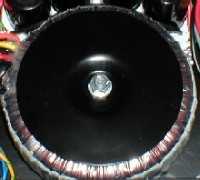 T1 is my transformer, pictured left. A
500VA toriodal transformer which is the same secondaries as shown - well 2x 25V. To see how
this can be wired into a 25-0-25 configuration as required, see
this page.
T1 is my transformer, pictured left. A
500VA toriodal transformer which is the same secondaries as shown - well 2x 25V. To see how
this can be wired into a 25-0-25 configuration as required, see
this page.
Then there is the split and as that design shows - my also has two bridge rectifiers and four capacitors. Unlike that design - mine isn't a kind of 'half mono-block' for each amplifier. That was designed for two.. I have seven.
One bridge and set of capacitors drives all my P3A's - all four of them. The other half drives (or will drive) all the LM3886's - rears and centre.
Bridge rectifiers are labelled as KBPC3504. These a big bolt down rectifiers. The cost of these doesn't seem to rise much so you might as well get the best possible. These will easily give me a lot of years life in my amp without any problems what so ever. They also give the maximum efficiency which is excellent for getting that +/-35V required.
The Boomerang
Its a nickname, not a technical term!
I labelled this so because it is shaped that way. It is also quite a unique circuit board in design as I did not etch it.
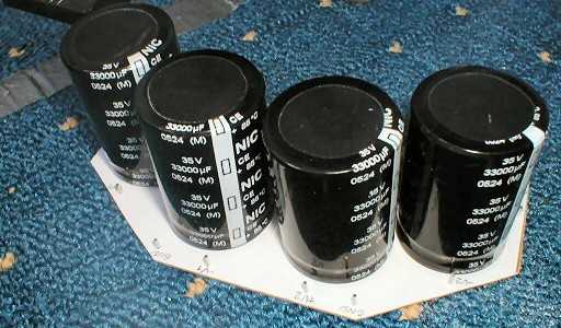
The boomerang contains all the power supply capacitors - the four of them. These are big caps too with each one capable of holding a charge of around 33,000uF. Ebay bargain - I wouldn't have gone that high if this wasn't so tempting. Since these are PCB mount with tiny pins though I would need a PCB.
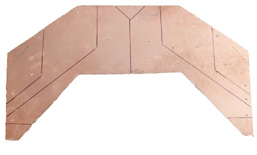
Marking out the layout.
The sheer size of this board and simple layout made me think it would be a waste of expensive etch resist pen ink and PCB etchant solution. My alternative was to use pernament ink to make out breaks in the copper I needed and then use a cutting disk on a rotary tool (A.K.A. dremmel) so take the copper off (but not actually cut the board). The results were good. Above is the marking, below is the result after attacking it with the cutting disk.
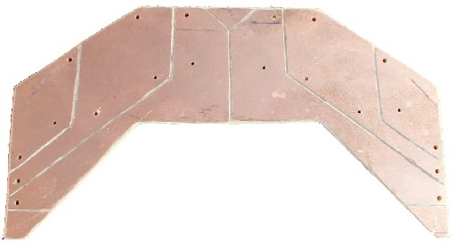
Result. Remember to check each section of copper is not shorted with any other.
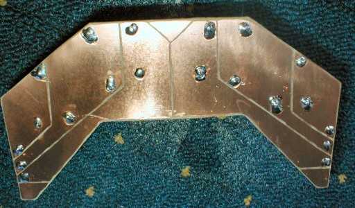
The boomerang - cleaned and soldered.
And finally, from above.
The shape took its form for the position it would be in. The idea is it would lay next to the transformer and it would shape around the side of it. The main advantage for this was so I could stack the capacitors on the board so that they would take up less overall width than they would side-by-side, which would make things a bit too squashed in.
Loop Breaker and Star Ground
 An extremely simple circuit
board. Again I did not etch this one as it would only need to sections of copper - one for the earth,
the other for the star ground. Between the earth and the ground is D1, D2, R1 and C1 as shown in
Rod's schematic. This is a loop breaker - to prevent an earth loop which causes audio systems to
hum.
An extremely simple circuit
board. Again I did not etch this one as it would only need to sections of copper - one for the earth,
the other for the star ground. Between the earth and the ground is D1, D2, R1 and C1 as shown in
Rod's schematic. This is a loop breaker - to prevent an earth loop which causes audio systems to
hum.
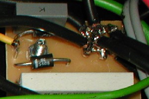
The picture left is not the clearest picture I could have done of it - but you get the idea. The long white resistor as a 7W 10 ohm wirewound, the capacitor is 01.uF 250AC capacitor. Note: It must be AC. Diodes I got are 1N5408, these ought to have the necessary power requirements ;)
All grounds connect to the other side of this board, as can be seen by the mass of black wires. This is the idea behind a star ground circuit. The earth wire of course connects to the case and the earth pin on my mains input socket.
Crossover power supply
The croosover power supply consists of two ESP projects:
Project 05 - Preamplifier PSU.
Project 102 - Simple Pre-regulator.
Project 05 is the main regulated supply I need to power the op-amps on the active crossover. It consists of 7815 and 7915 pairs to produce the regulated +/-15V required for the task.
My crossover board had P05 built into it, except for the filter caps which are held separately and
shown on the right.
Building P05 is not very hard, just make sure you take notice of the different pinouts on the regs and note the correct polarity of the capacitors.
Unfortunately, the regulators usually allow a maximum on +30 or -30 input voltage. I did not want a separate transformer so I decided that I would construct Rod's pre-regulator. This is an ideal little circuit which would allow my to bring down the voltage to +/-24V using some zener diodes, resistors and two well known transistors. The cost was small in price and only a bit of heat is generated by the transistors and 820ohm resistors. The big 3W resistor is another loop breaker to keep the amplifier and crossover loops from becoming complete and introducing hum.
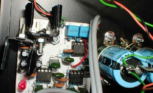
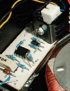
My pre-regulator circuit. On the other side of the case is a heatsink - but this barely gets warm.
Again it is a simple circuit, but I did make a small mistake at first. This caused the transistors to heat to temperatures which I could not manage with a simple heatsink. However I found out that increasing the values of R1 and R3 from 470 ohm to 820ohm fixed this greatly and the power dissipation in the resistors should cause no problems for my 0.6W resistors as the power is not above.
I assumed the worst case - +/-40V:
P = (40-24)² / 0.82 = 312mW = 0.3W
They do get a little warm, but not by enough to cause problems. One final note is to make sure mica washers and bushes are used as in no circumstance should the tabs of the transistors short. My picture shows this clearly.
Soft Start Circuit
Without the soft start circuit, there is stress on:
Fuses, nuisance blowing can happen
Transformer - the inrush current can stress the windings
Bridge rectifier - current is higher than normal as it must also charge initially empty filter capacitors
Capacitors - inrush can exceed the rated ripple current
Fortunately, Rod Elliott provides details for a soft start circuit, which is here.
The idea of the circuit is to switch current limiting resistors into the path of the mains electricity for less than half a second, which limits the inrush current to about 125% of the normal current. The article is recommended reading and may convince you to build the circuit too as it does have its benefits.
However:
The soft start circuit involves a lot of mains voltage wiring. Please do not
construct it unless you are suitably qualified. Death or serious injury can result!
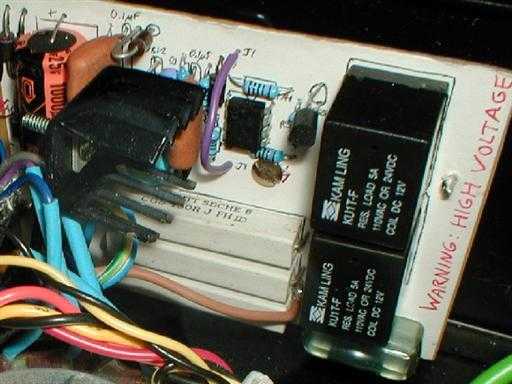
My soft start circuit board.
My version is based on the last design in Rod's project article - the so called PCB version. This simply works very well with an external transformer. I had purchased an EI 9V transformer as required for this circuit.. but the size of such EI transformer to produce 2A was quite large - not to mention it is an EI type which means magnetic flux will be everywhere around it and therefore affect the sound quality of my power amp.
![]() I purchased a 4 toriodal
transformer bargain on ebay, and one of the four (the smallest) was a 30VA 2x18V toriodal. This
would be more ideal - except I am now at 18V AC rather than 9V I originally wanted.
I purchased a 4 toriodal
transformer bargain on ebay, and one of the four (the smallest) was a 30VA 2x18V toriodal. This
would be more ideal - except I am now at 18V AC rather than 9V I originally wanted.
My solution was simple. I connected the windings of the toriod in parallel (not series as before with the 500VA toriod) so I have 18V AC at its full 1.67A. Then I made a simple four diode bridge to convert this to DC and run it into a 7812 regulator (with 1000uF input filter cap). This got me the 12 volts DC I needed for the soft start circuit, including its relays.
The transformer has enough of power for the fan controller too. This gives the audio electronics total noise immunity from the soft start circuit and fans.
 The board contains the soft
start circuit (op-amp version), a 7812 regulator circuit for it and also contains the all important fuse.
2.5A slow blow (time delay) is the correct rating and will also accommodate for the 30VA transformer.
The circuit board also contains a 3-pin IEC mains input. This I modified for PCB mounting and it
works very well, shown on the right.
The board contains the soft
start circuit (op-amp version), a 7812 regulator circuit for it and also contains the all important fuse.
2.5A slow blow (time delay) is the correct rating and will also accommodate for the 30VA transformer.
The circuit board also contains a 3-pin IEC mains input. This I modified for PCB mounting and it
works very well, shown on the right.
I also stuck an LED on the circuit board - this was simply some reassurance for myself when I first powered the amp. The board did work first time no problems and it works very well. The delay between relays switching is about 02.-0.3 seconds (certainly less than half). There is no dimming of house lights either in the switch on process - this is in contrast to without this circuit where such dimming would be very noticeable.
Fan controller
 At present, this remains incomplete.
The circuit is built, but it is not correctly working yet as it does need the correct value resistors to work
properly. This cannot happen until I purchase some 60mm fans and get their current rating. The
60mm's will be used to cool the P3A's when they work hard. The board is in place though.. and here
is a quick photo and description.
At present, this remains incomplete.
The circuit is built, but it is not correctly working yet as it does need the correct value resistors to work
properly. This cannot happen until I purchase some 60mm fans and get their current rating. The
60mm's will be used to cool the P3A's when they work hard. The board is in place though.. and here
is a quick photo and description.
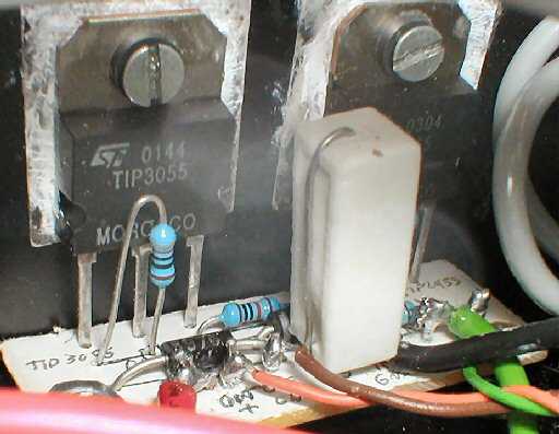
As said before, this circuit is based on another page from the ESP site. Project 42 to be precise.
My circuit is based on the second schematic in there as it was initially designed to run off the amplifier PSU. However I changed my mind, but the design still proved useful as I would be dealing with about 25V DC or so from my secondary transformer - which turned out to be 18V AC.
My board is very small, yet should work fine once I get the proper resistor for R7. At the moment all that happens is the fans spin, despite the setting of VR1. In theory an LED will also light once the fans are switched on via Q2.
VR1 itself is a multiturn pot that is accessible from the side of the case and turned by a slot head screwdriver. This makes it simple to adjust the temperature sensitivity of the circuit without the cover off, but also prevents the settings from accidently being changed by requiring a screwdriver. I have tried and failed with my finger nail.
A uA741 op-amp is what I used for the control - it doesn't need an expensive noise free op-amp at all. 1N4004 diodes will be distributed throughout the amp (more wires!) when I decide to solder them up.