
TDA7317 DIY Guide - 5-band Stereo Digital Controlled Graphic Equaliser
Warning: The TDA7317 is discontinued. It can still be found online and mine are from a Chinese auction site but do be aware there's always that risk it either doesn't work at all or performs badly when not brought from a reputable supplier.
Recommended Experience : intermediate to advanced, custom PCB needed, microcontroller needed
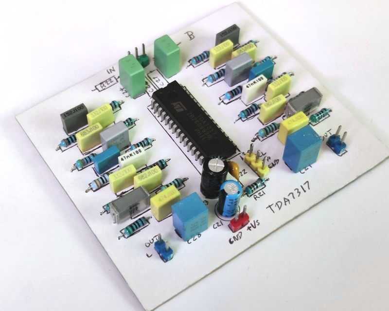
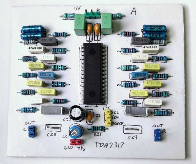
TDA7317 application
Quick facts TDA7317
- 5-band Equaliser
- Two possible I2C addresses, allowing daisy chain 10-band equaliser, or 4 channel equaliser
- Volume / attenuation control in 0.375dB steps
- ±14dB cut/boost per band in 2dB steps
- Power supply: 6V to 10V single supply only
- Datasheet available here
Guide
The TDA7317 is a single chip digitally controlled graphic equaliser that will allow you to build a fairly small graphic equaliser with passive components.
Alternatively, there is also the TDA7316 - a 4-band version in a smaller SO28 (surface mount) chip and apart from some slight pin-out differences and one less EQ band, all the information here to operate it is just as appropriate.
This equaliser is digitally controlled, which means it's still an analogue device that requires quite an extensive set of capacitors and resistors to make a complete equaliser. It is not DSP, and no conversion of the analogue signal actually occurs. The potentiometers (resistor strings) inside the chip are digital controlled though, which saves room over having multiple manual potentiometers everywhere and opens up the possibility of remote operation (infrared, Bluetooth, etc.).
This means you will need a separate microcontroller to control it. This might put-off novice builders, but I've included full details of my build based around a cheap microcontroller, display and rotary encoders. This can be programmed at the cost of buying (or building) a programmer.
The equaliser is stereo, making it applicable for small sized 'Hi-Fi' systems, car-radio (two channels), ghetto-blasters or small active stereo speakers. Do note though that it doesn't offer the possibility to adjust the EQ of each channel separately.
It also features a volume control which you can either use or ignore. The volume control has 47 0.375dB steps, but it's just volume and no L/R balance control is possible.
The TDA7317 is programmed by the I2C bus (also known as TWI) and can either be on address 0x84 or 0x86, depending on whether the ADDR pin 18 is connected to ground or left open. It supports the common bus speed of 100kHz but won't work with faster speeds.
This allows you to have two chips on the same bus - giving you the possibility of a stereo 10-band graphic equaliser, or 4-channel 5-band equaliser.
If your microcontroller has support for separate I2C/TWI channels (could be possible with software driven I2C), you can add even more chips if you want a multi-channel 10-band equaliser, for example.
The performance of the TDA7317 seems fine. I wouldn't say it's aimed for 'true' Hi-Fi systems, but it's capable and doesn't degrade the signal quality much. Its biggest weakness is each band adjustment is not very fine-tuned, at 2dB steps. You can get this down to about 1dB per step if you configure the filters to within 12dB min/max gain.
A fully analogue graphic or parametric equaliser will be superior, as will an advanced DSP chip. The TDA7317 solution though does still offer an interesting 'in-between' option that allows you to program EQ settings without the complexity of building or setting up a DSP.
The control method on the I2C bus is quite simple. Only two wires (a clock signal, and data signal) are needed and bytes are sent out serially one bit at-a-time (more details below).
Many microcontrollers are capable of driving the I2C bus either with built in hardware or by software bit-banging and chances are the manufacturer, software compiler or someone else has written a library for I2C/TWI communication - it's extremely popular!
I typically use PIC microcontrollers, and I've picked the PIC16F1824 for this build. Some PICs have I2C hardware support (the PIC16F1824 does), others don't. Arduino is a popular alternative though and very well supported by the community. You could also use a Raspberry Pi or other small computer. That's a bit heavy handed for a preamp, but if your project already uses one for other features then the Pi's native I2C bus support makes communicating with the TDA7317 quite easy.
Circuit Schematic
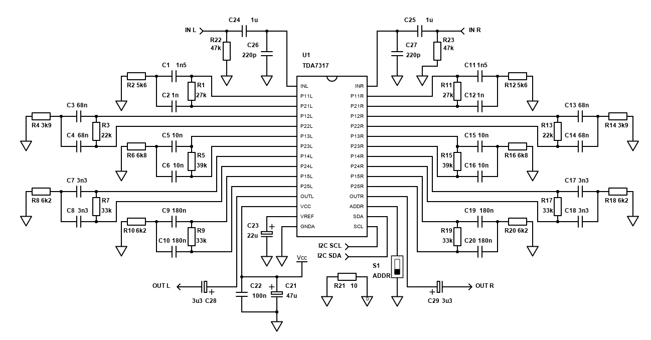
The schematic above is based on the application circuit ST Microelectronics datasheet. I've added a few components to the stereo output to block the DC offset, provide an input impedance that will work with many input sources and an input low pass filter for some RF/GSM noise suppression.
Note: The pull-up resistors for I2C data and clock are NOT shown in the schematic but are required. Typically, they are installed at the microcontroller as you only need one pull-up resistor on the clock and data for all devices connected on the bus. These pull-up resistors should be around 4k7 - one from the I2C DATA (SDA) input to the microcontroller power supply (i.e., +5V or +3.3V), and one from the I2C CLOCK (SCL) input to the microcontroller power supply again.
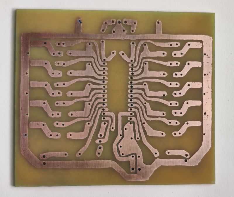
The TDA7317 is a SDIP chip, but it does not have the standard 2.54mm (0.1 inch) pin spacing of traditional DIP chips. That means it isn't going to fit into Stripboard/Veroboard, and it also won't fit any commonly available IC sockets. The distance between each pin is about 1.8mm (1.778mm), so a custom PCB is necessary.
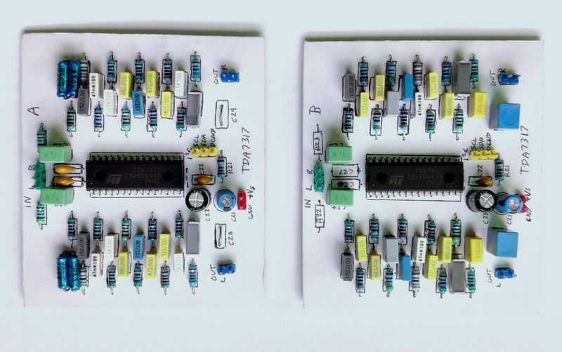
A PCB layout is included in the datasheet. It's about 96mm x 84mm, replicated below:
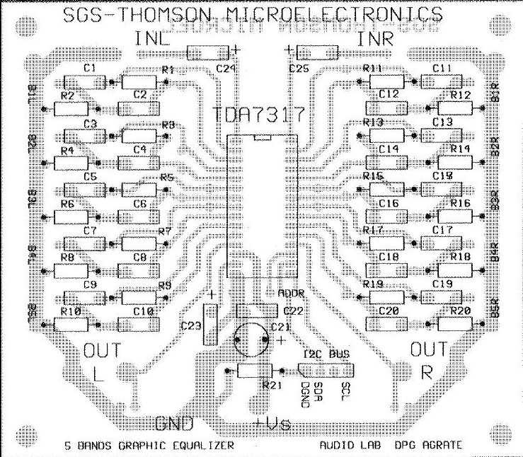
I decided to adjust it slightly myself to make it more compact (80 x 70mm) and give support for capacitors that have the typical 5mm pin spacing, or 10mm pin spacing (as my 220nF capacitors require). I've also added input RF filter capacitors and resistors.
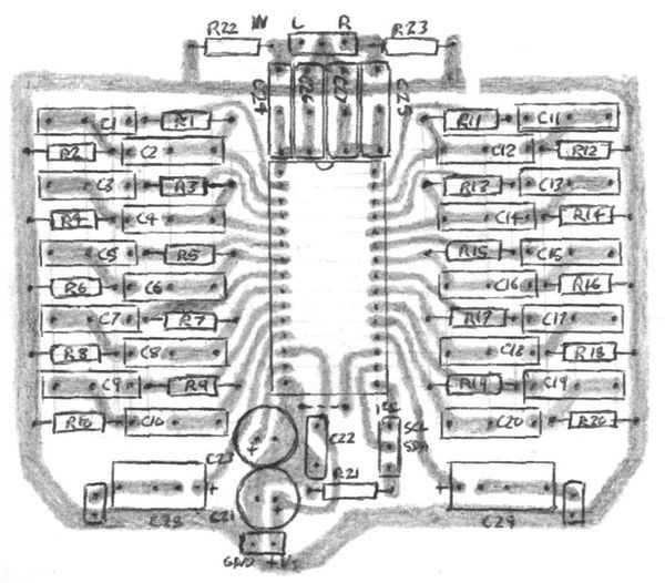
Both boards have a resistor (R21) below the TDA7317 chip used to connect the digital and analogue grounds together. In order for the TDA7317 to work, they have to be connected somewhere. If your PSU shares the same common ground with the microcontroller PSU though (as my dual output PSU below does), you should leave this resistor out or just not make this ground connection.
Components
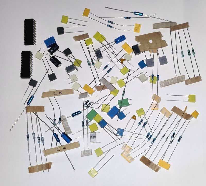
Quite a lot of components are required for the TDA7317 - above shows most (but not all) of the selection for two TDA7317 boards to build a 10-band EQ.
Below is a list of components for a 5-band EQ.
| # | Type | Quantity |
|---|---|---|
| U1 | TDA7317 | 1 |
| R1,R11 | 27k ohm Resistor, ¼W Metal Film, 1% | 2 |
| R2,R12 | 5.6k ohm Resistor, ¼W Metal Film, 1% | 2 |
| R3,R13 | 22k ohm Resistor, ¼W Metal Film, 1% | 2 |
| R4,R14 | 3.9k ohm Resistor, ¼W Metal Film, 1% | 2 |
| R5,R15 | 39k ohm Resistor, ¼W Metal Film, 1% | 2 |
| R6,R16 | 6.8k ohm Resistor, ¼W Metal Film, 1% | 2 |
| R7,R19,R17,R19 | 33k ohm Resistor, ¼W Metal Film, 1% | 4 |
| R8,R10,R18,R20 | 6.2k ohm Resistor, ¼W Metal Film, 1% | 4 |
| Rx,Ry | 4k7 ohm Resistor, Carbon, 5% - for I2C bus if required | 2 |
| C1,C11 | 1.5nF Capacitor, Polyester Film/Box | 2 |
| C2,C12 | 1nF Capacitor, Polyester Film/Box | 2 |
| C3,C4,C13,C14 | 68nF Capacitor, Polyester Film/Box | 4 |
| C5,C6,C15,C16 | 10nF Capacitor, Polyester Film/Box | 4 |
| C7,C8,C17,C18 | 3.3nF Capacitor, Polyester Film/Box | 4 |
| C9,C10,C19,C20 | 15nF Capacitor, Polyester Film/Box | 4 |
| C21 | 47µF Capacitor, 25V+ Electrolytic | 1 |
| C22 | 100nF Capacitor, 50V+ Ceramic / MLCC | 1 |
| C23 | 22µF Capacitor, 25V+ Electrolytic | 1 |
| C24,C25 | 1µF Capacitor, Polyester Film/Box | 2 |
| C26,C27 | 220pF Capacitor, 50V+ Ceramic | 2 |
| C28,C29 | 4.7µF Capacitor, 25V+ Electrolytic, or Polyester (Best) | 2 |
| S1a,S1b | Single jumper, DIP switch or wire link | 2 |
| +Vs Header | 2.54mm header 2-pin | 1 |
| In L/R,Out L/R,Bus Header | 2.54mm header 3-pin | 3 |
| Cable, connectors | ~ |
52 components are required, including the chip, excluding headers / links / wires etc.
Most of the components are capacitors, and many of them are in the audio path and therefore should all ideally by polyester capacitors. C24, C25, C28 and C29 can be electrolytic if you prefer to save money however if these are used, the positive terminal must face the TDA7317.
C21 and C23 are standard electrolytic capacitors. Just ensure they are rated 16V or better and oriented per the schematic. Both should be close to the TDA7317 in your PCB layout, especially C23.
C22, C26 and C27 are standard ceramic capacitors or MLCC. C22 must go as close to the TDA7317 as you can get it in your layout.
Most of the resistors are recommended to be 1% metal film, 1/4W or better. Only the resistors on the I2C bus (two pull-up resistors not shown) can be 5% carbon as they're not in the audio signal.
The components shown above are close to the standard datasheet recommendation, but I've adjusted some components to use more common values (i.e., E6 capacitors). You can, however, alter the band pass filters of each band by adjusting the capacitors and resistors appropriately, see below.
Below, I've suggested components for both a 5-band equaliser and 10-band equaliser. These aim for a max gain of 12dB for better control, and capacitor values that are more common. I find E12 capacitor series hard to get or expensive in the UK, so I've kept all capacitor suggestions to E6 values (10, 15, 22, 33, 47, 68). Metal Film 1% resistors in the E24 range are quite common and cheap though, so my suggestions are from that range.
A thing to note though, is E6 capacitors are usually ±20% tolerance - meaning that 15nF capacitor could be between 12nF and 18nF. This could affect the centre frequency significantly, as well as gain and Q, so you may want to get more capacitors than you need and measure their actual value.
Typically, with a graphic EQ, you'll want to spread the control equally across octaves. The industry standard 10-band EQ is 32Hz, 63Hz, 125Hz, 250Hz, 500Hz, 1kHz, 2kHz, 4kHz, 8kHz and 16kHz. The 5-band example in the TDA7317 datasheet is 62Hz, 250Hz, 1kHz, 3.5kHz and 10kHz.
The formulas on page 4 of the datasheet set the band filter centre frequency, Q and max gain. The centre frequency and Q are both constant at whichever boost/cut setting is sent to the chip.
To help with calculating the components, I've made a spreadsheet you can download here. This should open in either Libre Office or Microsoft Excel, or any other Office program that supports the OpenDocument Spreadsheet (.ods) file.
Plugging the values into a spreadsheet is quite a slow way of finding what you want though, so I've also written a Python script that you can download and use. Simply edit the top of the file to put you desired frequency range, Q range and max gain range. The program then explodes out all the reasonable combinations of E6 capacitor values and E24 resistor values, calculates the frequency and narrows down, then calculates filter Q, and narrows the results further, before finally calculating the gain and narrowing down to a final set of values where you can pick the closest.
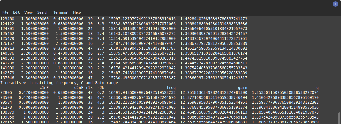
The program uses E6 capacitor range and E24 resistor range, but it's easy to alter it and add/remove value ranges.
Below are the suggested components for a 5-band EQ. This is similar to the datasheet option with 12dB gain, but I've pushed Q lower for a wider bandwidth and stuck with E6 range capacitors, E24 range resistors.
A 5-band EQ should cover every 2 octaves, meaning the Q should be 0.66. Range is best started at 63Hz, and quadrupling after - so 63, 252, 1000, 4000, 16000. The TDA7317 datasheet suggestion has the last two bands at 1.7 and 1.5 octaves though, so filter Q should be 0.8 and 0.92. The datasheet does suggest a Q of around 1 to 1.2 though, which will leave dips in the response at max/min settings (see figure 6, page 10).
Note that I've spread the bands per the datasheet for best THD performance. In software, you'll need to start at band 5 for the lowest frequency, then to 2, 3, 4 and 1.
| Band | C1 | C2 | R1 | R2 | Freq Hz | Max Gain dB | Q |
|---|---|---|---|---|---|---|---|
| 1 | 6.8nF | 2.2nF | 8.2k | 2k | 10160 | 12.25 | 0.87 |
| 2 | 220nF | 47nF | 11k | 3.3k | 260 | 11.47 | 0.7 |
| 3 | 47nF | 10nF | 13k | 3.9k | 1027 | 11.48 | 0.69 |
| 4 | 22nF | 6.8nF | 7.5k | 2k | 3360 | 11.74 | 0.82 |
| 5 | 330nF | 68nF | 30k | 9.1k | 64 | 11.44 | 0.68 |
I've not tested this component selection. The low value resistors may push the limits of the TDA7317, but they are still within the stated range.
For a half-decent equaliser, an octave per band is better - so I've made a 10-band EQ with two chips. Ideally, a Q of 1.4 should be aimed for in a 10-band (1 per octave) EQ. Again, the max gain of 12dB should be aimed too.
Below are the components for a 10 band EQ.
| Band | C1 | C2 | R1 | R2 | Freq Hz | Max Gain dB | Q |
|---|---|---|---|---|---|---|---|
| 1.1 | 680pF | 1.5nF | 30k | 3.3k | 15840 | 11.68 | 1.40 |
| 1.2 | 47nF | 100nF | 27k | 3k | 258 | 11.77 | 1.40 |
| 1.3 | 6.8nF | 15nF | 47k | 5.1k | 1018 | 11.76 | 1.41 |
| 1.4 | 4.7nF | 10nF | 18k | 2k | 3869 | 11.77 | 1.40 |
| 1.5 | 100nF | 220nF | 51k | 5.6k | 63.5 | 11.7 | 1.40 |
| 2.1 | 1.5nF | 3.3nF | 27k | 3k | 7948 | 11.62 | 1.39 |
| 2.2 | 68nF | 150nF | 39k | 4.3k | 121.7 | 11.66 | 1.40 |
| 2.3 | 22nF | 47nF | 30k | 3.3k | 497 | 11.82 | 1.41 |
| 2.4 | 3.3nF | 6.8nF | 51k | 5.6k | 1988 | 11.99 | 1.42 |
| 2.5 | 220nF | 470nF | 47k | 5.1k | 32 | 11.90 | 1.41 |
Again, bands are staggered for THD performance over the two chips, so in software you would follow the band order of 2.5, 1.5, 2.2, 1.2, 2.3, 1.3, 2.4, 1.4, 2.1 and 1.1.
It should be noted that the results are calculated with exact capacitor and resistor values. E24 resistors should have a 1% tolerance, so the results won't be altered much by the resistors, but E6 capacitors have a ±20% tolerance which could alter the frequency, gain and Q more than desired, so as mentioned above, get more capacitors than you need and measure them with a component tester or multimeter and select the capacitors closest to the intended value.
A parts list for the 10-band EQ is below. The part numbers suffixed 'a' are for the first chip, 'b' the second.
| # | Type | Quantity |
|---|---|---|
| U1a,U2b | TDA7317 | 2 |
| R1a,R11a,R5b,R15b | 30k ohm Resistor, ¼W Metal Film, 1% | 4 |
| R2a,R12a,R6b,R16b | 3.3k ohm Resistor, ¼W Metal Film, 1% | 4 |
| R3a,R13a,R1b,R11b | 27k ohm Resistor, ¼W Metal Film, 1% | 4 |
| R4a,R14a,R2b,R12b | 3k ohm Resistor, ¼W Metal Film, 1% | 4 |
| R5a,R15a,R9b,R19b, R22a,R23a | 47k ohm Resistor, ¼W Metal Film, 1% | 6 |
| R6a,R16a,R10b,R20b | 5.1k ohm Resistor, ¼W Metal Film, 1% | 4 |
| R7a,R17a | 18k ohm Resistor, ¼W Metal Film, 1% | 2 |
| R8a,R18a | 2k ohm Resistor, ¼W Metal Film, 1% | 2 |
| R9a,R19a,R7b,R17b | 51k ohm Resistor, ¼W Metal Film, 1% | 4 |
| R10a,R20a,R8b,R18b | 5.6k ohm Resistor, ¼W Metal Film, 1% | 4 |
| R3b,R13b | 39k ohm Resistor, ¼W Metal Film, 1% | 2 |
| R4b,R14b | 4.3k ohm Resistor, ¼W Metal Film, 1% | 2 |
| R21a,R21b | 10 ohm Resistor, ¼W Metal Film, 1% | 2 |
| Rx,Ry | 4k7 ohm Resistor, Carbon, 5% - for I2C bus if required | 2 |
| C1a,C11a | 680pF Capacitor, Polyester Film/Box | 2 |
| C2a,C12a,C1b,C11b | 1.5nF Capacitor, Polyester Film/Box | 4 |
| C3a,C13a,C6b,C16b | 47nF Capacitor, Polyester Film/Box | 4 |
| C4a,C14a,C9a,C19a | 100nF Capacitor, Polyester Film/Box | 4 |
| C5a,C15a,C8b,C18b | 6.8nF Capacitor, Polyester Film/Box | 4 |
| C6a,C16a | 15nF Capacitor, Polyester Film/Box | 2 |
| C7a,C17a | 4.7nF Capacitor, Polyester Film/Box | 2 |
| C8a,C18a | 10nF Capacitor, Polyester Film/Box | 2 |
| C10a,C20a,C9b,C19b | 220nF Capacitor, Polyester Film/Box | 4 |
| C2b,C12b,C7b,C17b | 3.3nF Capacitor, Polyester Film/Box | 4 |
| C3b,C13b | 68nF Capacitor, Polyester Film/Box | 2 |
| C4b,C14b | 150nF Capacitor, Polyester Film/Box | 2 |
| C5b,C15b | 22nF Capacitor, Polyester Film/Box | 2 |
| C10b,C20b | 470nF Capacitor, Polyester Film/Box | 2 |
| C21a,C21b | 47µF Capacitor, 25V+ Electrolytic | 2 |
| C22a,C22b | 100nF Capacitor, 50V+ Ceramic / MLCC | 2 |
| C23a,C23b | 22µF Capacitor, 25V+ Electrolytic | 2 |
| C24a,C25a,C24b,C25b | 1µF Capacitor, Polyester Film/Box | 4 |
| C26a,C27a | 220pF Capacitor, 50V+ Ceramic | 2 |
| C28b,C29b | 4.7µF Capacitor, 25V+ Electrolytic, or Polyester (Best) | 2 |
| S1a,S1b | Single jumper, DIP switch or wire link | 2 |
| +Vs Header | 2.54mm header 2-pin | 2 |
| In L/R,Out L/R,Bus Header | 2.54mm header 3-pin | 6 |
| Cable, connectors | ~ |
That's a total of 102 components for the 10-band EQ.
Control Hardware
| # | Type | Quantity |
|---|---|---|
| U1 | PIC16F1824 | 1 |
| D1 | 1N5819 Schottky Diode | 1 |
| D3 | Standard LED | 1 |
| R4 | 270 ohm Resistor, ¼W Carbon, 5% (adjust to LED colour) | 1 |
| R6,R7,R10,R11 | 100k ohm Resistor, ¼W Carbon, 5% | 6 |
| R13,R14 | 4k7 ohm Resistor, ¼W Carbon, 5% - I2C pull up if required | 2 |
| C5 | 100nF Capacitor, 50V+ Ceramic / MLCC | 4 |
| C6 | 47µF Capacitor, 10V+ Electrolytic | 1 |
| Headers | 2.54mm headers, as appropriate | ~ |
| Cable, connectors | ~ |
The TDA7317 cannot function alone, and you'll need a small microprocessor / microcontroller in order to control the TDA7317.
Below is a schematic for using the PIC16F1824 microcontroller with rotary encoders to control the equaliser, and an LED for debug/output.
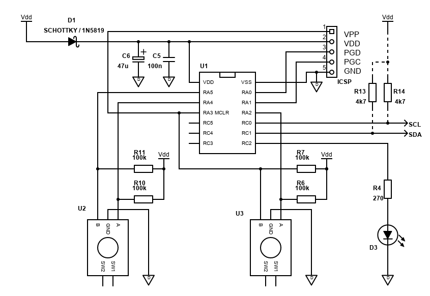
The communication between the microcontroller and the TDA7317 (not shown) is done via an I2C bus (SCL and SDA). Also not shown, but an SSD1306 128x32 display is also on the same I2C bus and therefore requires no extra I/O pins.
I2C requires two wires (a data signal SDA and clock signal SCL) and is quite simple to understand and code. I suggest picking a microcontroller with I2C leader (master) support built in as it makes writing the code a little easier, however writing a fully software-based solution is also possible.
I have shown two pull up resistors R13 and R14 on the I2C bus. Be aware though that many I2C modules may have pullup resistors included, and they may be behind an on-board LDO voltage regulator too, like how my SSD1306 module was configured. Though there is usually no harm in having two 4k7 pull up resistors in parallel (giving 2.25k), going too low might exceed the current capability of the microcontroller or peripherals.
I used the extra pull up resistors in my build so I could diagnose running the TDA7317 boards alone, as I initially had trouble, although this was ultimately down to using a cable to the TDA7317 which was twisted - you shouldn't twist data cables normally, unless twisting with the ground.
Control of the equaliser is done via two quadrature rotary encoders (which do not have push buttons). These are directly connected to the PIC and some decent code I found was ported to BoostC and support added for two encoders by myself. This code does not require the encoders to be debounced as it checks movement validity. I did originally use resistors/capacitors to do the debouncing, but some of the ports the encoders are connected to are TTL only (not Schmitt Triggers), so it didn't work well.
Note that one encoder is connected to RA3. This is an input only port that is also used during high voltage programming, but as a rotary encoder is normally open when in any of its detents, it doesn't interfere at all during programming - just don't turn the encoder whilst programming!
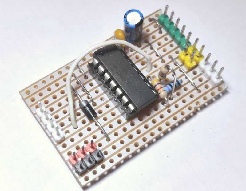
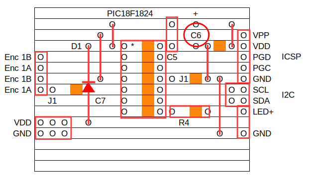
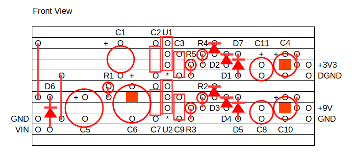
To keep things simple, I built the control board on Stripboard, and the encoders with their 100k pull-up resistors on a separate piece of Stripboard to allow easy mounting when required. Below is the layout of the control board. A layout for the encoders I'll leave to you as their pinout/size varies.
I've included snippets of the program below to explain each feature, but the full code is on github.com here. All code is written in C, specifically BoostC from SourceBoost. More details below.
For those who prefer other microcontrollers (such as the popular Arduino), you'll need to consider the following in your code:
- I2C support - it's common, but not guaranteed
- An initialisation routine to tell your microcontroller what pins the bus is connected to, I2C baud rate as well as initialisation for other peripherals.
- Functions to send the relevant bytes to the TDA7317
- Controls to interact with a human, such as buttons, rotary encoders, IR remote control, LCD/LED displays etc - all per your preference!
The datasheet gives you good examples of what data to send to the TDA7317 in order to control it.
For my build - I kept it simple. User control is via two rotary encoders. One is used to select the band to adjust (or volume). The other adjusts the band (or volume) up or down. That's it! No buttons or anything else.
The current band settings and volume are saved to the onboard EEPROM about every 30 seconds, if they have changed, so when power is removed the last setting is remembered.
You could easily expand this to include a couple of buttons for saving and recalling multiple presets, or built-in presets like the funk, pop, rock, jazz etc. settings some equalisers have, if you're into that sort of gimmick!
The LED does nothing either, so you could use that pin as an input for an IR receiver and add remote control.
Note that the PIC and SSD1306 display are driven by 3.3V. The SSD1306 has an onboard 3.3V LDO regulator that can be bypassed by bridging R5 on the module. The module also includes pull up resistors, but they are after the regulator, allowing you to use a 5V microcontroller if you want. You have to be careful here as powering by 5V would keep the I2C bus at a safe 3.3V for the SSD1306 bus input pins but means you cannot connect external pull up resistors to 5V and this may mean the microcontroller cannot accurately read any ACK signal from the relevant peripheral.
I run the PIC16F1824 off 3.3V anyway and the TDA7317 supports the I2C at this voltage too (datasheet says min 3V for input high bus voltage).
Power Supply
| # | Type | Quantity |
|---|---|---|
| U1,U2 | LM317T 3-pin adjustable positive regulator | 2 |
| D1,D2,D3,D4,D5,D6,D7 | 1N400x (i.e., 1N4004) Rectifier Diode | 7 |
| R1 | 10 ohm Resistor, ¼W Carbon, 5% | 1 |
| R2,R4 | 240 ohm Resistor, ¼W Metal Film, 1% | 2 |
| R3 | 1.5k ohm Resistor, ¼W Metal Film, 1% | 1 |
| R5 | 390 ohm Resistor, ¼W Metal Film, 1% | 1 |
| C1 | 220µF Capacitor, 35V+ Electrolytic | 1 |
| C2,C3,C7,C9 | 100nF Capacitor, 50V+ Ceramic / MLCC | 4 |
| C4,C8,C10,C11 | 10µF Capacitor, 25V+ Electrolytic | 2 |
| C5,C6 | 1000µF Capacitor, 35V+ Electrolytic | 2 |
| In,Out,Out | 2.54mm header, 2-pin | 3 |
| Cable, connectors | ~ |
The TDA7317 needs a single supply power supply giving 6 to 10V DC. It must be regulated. The simplest version is to use a 9V regulated external PSU (wall-wart) dedicated to the TDA7317, and a separate 3.3V PSU for the microcontroller and peripherals.
My build uses a single 12V supply for convenience, which is then regulated down to 9V using an LM317T and regulated down to 3.3V using another LM317T. The LM317T is a simple to use adjustable linear regulator who's output voltage can be configured by choosing the right values for a couple of resistors - see REUK.co.uk - LM317 Voltage Calculator. The efficiency of the 3.3V regulator will only be 27%, but the microcontroller and display do not require much power at all and no heatsink is required for my build.
The supply current of the TDA7317 will be even lower - just a few mA max. It should be easy to find or build a power supply exceeding that many times. Even running the chip off a 9V PP3 battery seems possible (though 6 1.5V AA/LR6 would be better)!
Having a power supply dedicated to the TDA7317 is recommended and reduces your chances of hitting ground loop issues.
Below is the schematic of the PSU I used. This is fed by an external 12V DC PSU.
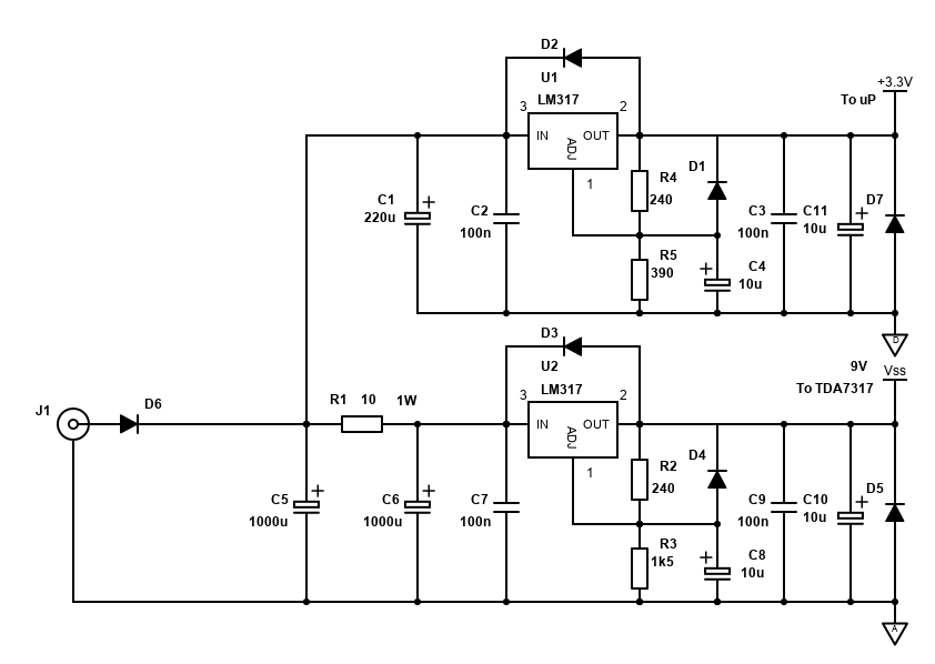
Although the current draw is very low at 10mA maximum, there is no standby possibility though, so I suggest switching the chip on/off via a physical switch at the unit, or small relay, especially if battery operated.
D6 is for simple reverse polarity prevention, but introduces some voltage drop. Feel free to leave it out if reverse polarity prevention is not required. C5, C6 are also quite large to ensure good filtering, but you may find smaller capacitors will work fine too.
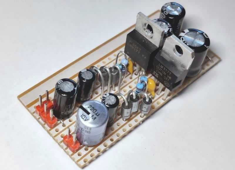
For my build, I soldered the PSU onto Stripboard, as the layout is simple enough. Feel free to adjust or implement on a proper PCB to save size a bit.
The PSU is effective and works well with no hum when powered from an old Uniross 300mA unregulated AC adaptor. If you use a switching PSU AC adaptor though (these are the smaller ones), some high frequency noise might come through and this can be reduced by adding an LC (inductor) filter after the 9V output.
If you are building a fully integrated unit with a mains input, you could build a simple small power supply using a PCB mount 9V 1.5VA AC transformer (with fuse before it) followed by a bridge rectifier (voltage will be about 12V DC after this), capacitor and 9V regulator and associated components as shown above.
If you do wire a power supply using mains voltage, you must be suitably qualified, Death or serious injury may result from mistakes.
If you intend to regulate the power to 9V from another DC power source in the system (such as the amplifier PSU), you might hit ground loop issues, particularly if switching power supplies are involved. In another build using a TDA7439, I used a linear regulator to drop the amplifier's PSU to 12V, followed by an isolated DC-DC convertor (12V to 12V), followed by a 9V linear regulator with coils and capacitors to suppress noise. See my STA540/TDA7439 amplifier build article for the details about this PSU that would also be suitable here.
Software
My example is available to download here, for SourceBoost BoostC.
This is based on the control hardware above, using a single PIC16F1824 as the microcontroller, with hardware I2C support. Two rotary encoders are used, and a cheap SSD1306 OLED display is used.
The code just supports controlling the volume and 10 bands (therefore needs two TDA7317 boards), which are adjusted by the two quadrature rotary encoders, with EQ and volume settings saved into EEPROM so that they are restored on power loss.
No option of IR control, EQ presets or any other ideas are present. I wanted to keep the code simple as I'm not adding it to any of my amplifier builds for now, but it may form part of a future project. The code only consumes 1671 words of flash memory (40.8% of the 4096 words available on a PIC16F1824), and 94 bytes of RAM (36.8% of the 256 bytes available). Most of that code usage will be for the SSD1306 display.
The microcontroller runs at 16Mhz, using the internal oscillator. This is to ensure swift processing for the SSD1306 display.
With regards to the display - I selected this 128x32 0.91" OLED display, as it is a cheap graphics capable display. Displaying the EQ bands on a classic 16x2 or 20x4 HD44780 compatible LCD wouldn't look good and there aren't enough custom characters to display the bars vertically as I would want.
I must say though, the 128x32 0.91" display is ridiculously small, even when close to it. If I was building this into its own unit, I would have chosen a larger display - a 2.23" SSD1305 128x32 display would start to be an improvement. Larger displays are available too, but driven by SPI instead, which would mean the I2C bus for the TDA7317 needs to be bit-banged.
Since this is an article about the TDA7317 Equaliser chip, I won't go into the details of the code that handles the output to the SSD1306 and just show that it the result on the display looks like this video:
I also won't cover the details on how the rotary encoders are handled in the code (see here instead), but the result of them is to either increment or decrement either volume or band boost/cut. I also won't cover the saving to EEPROM and timer.
First, the important variables I'm using:
// 10 band array. 5 bands for one TDA7317, 5 bands for the second
// 0 for no cut/boost, 1 to 7 for boost +2dB to +14dB, 9 to 15 for cut -2dB to -14dB
char iBands[] = {0,0,0,0,0,0,0,0,0,0};
// TDA7317 volume (applies to one chip only). 0 for max, 47 for min -17.625dB
char iVolume = 47;
// For UI - identifies which band or volume will be adjusted
// When 0 volume is active for adjusting, when 1 to 10, the relevant eq band is active for adjusting
char iActiveBand = 0;
I'm using the variables in RAM to hold the boost/cut setting for each band (I have 10, if using one chip, the array only needs to be 5 bytes long). The boost/cut settings in here are the 4 least significant bits that will get sent to the TDA7317.
Volume is stored in a separate variable. All 8 bits of this variable will be sent to the TDA7317 (just one of them actually). Only 6 bits are relevant, and the max attenuation for the TDA7317 is just -17.625dB, so the variable is capped to a maximum of 47. 0 indicates no attenuation (the minimum) - in other words - full volume.
Adjusting these variables is done by the actionRotaryAdjust function. This takes direction as a parameter with 3 being up, and 4 being down.
// Action for the second encoder - adjust the relevant band
void actionRotaryAdjust(char direction) {
    if (direction) {
        char iAdjustBand = iActiveBand - 1;
        char iBand = 0;
        if (iActiveBand != 0) {
            iBand = iBands[iAdjustBand];
        }
        if (direction == 3) {
            if (iActiveBand == 0) {
                // increase volume, which means decrementing attenuation iVolume
                if (iVolume > 0)
                    iVolume--;
            } else {
                // nothing happens if band is 7 (max boost)
                if (iBand < 7) {
                    // if band is 0 or in boost, increment boost
                    iBand++;
                } else if (iBand > 8) {
                    // if band is in cut, decrement cut
                    iBand--;
                }
                if (iBand == 8) {
                    // 8 should reset to 0
                    iBand = 0;
                }
                iBands[iAdjustBand] = iBand;
            }
            cTask.TASK_ENCODER_ADJUST = 1;
        } else if (direction == 4) {
            if (iActiveBand == 0) {
                // decrease volume, which means incrementing attenuation iVolume
                if (iVolume < 47) // Min is 47
                    iVolume++;
            } else {
                // nothing happens if band is 15 (max cut)
                // If currently 0 (no boost/cut), go to cut 9
                if (iBand == 0) {
                    // 8 should reset to 0
                    iBand = 9;
                } else if (iBand <= 7) {
                    // if band is in boost, decrement boost
                    iBand--;
                } else if (iBand < 15) {
                    // if band is in cut, cut further
                    iBand++;
                }
                iBands[iAdjustBand] = iBand;
            }
            cTask.TASK_ENCODER_ADJUST = 1;
        }
    }
}
You can see in here that the variables are adjusted appropriately.
If the active band is 0 (volume), then the iVolume variable is adjusted. A clockwise direction should increase volume, and that means decreasing attenuation (iVolume--). Once 0 is reached, no further decrement is possible.
Anti-clockwise decreases volume, therefore, increases attenuation (iVolume++), capped at the maximum attenuation of 47 (-17.625dB).
In the EQ bands, the logic is a little more complex.
Turning clockwise, the band should be boosted, or the cut reduced if currently in cut. Bit 3 of each byte in iBands is the boost/cut indicator. 0 means boost. Bits 2 to 0 are the boost/cut value from 0 to 7 (representing ~2dB steps).
Therefore, when the variable is less than 7, we're in boost - increase the boost (iBand++). This includes taking the band from neutral 0 to 1 (+2dB). When more than 8, we're in cut - decrease cut (iBand--). At 8 - this is -2dB cut, so the next increase of the band is to neutral 0.
The Anti-clockwise movement of the band is similar - boost should be reduced if currently in boost, and cut should be increased if in cut.
That's all the variable control to worry about - now how to send it:
// define TDA7317 address
#define	tda7317_addr1	0x84 // Base address
#define	tda7317_addr2	0x86 // Base address

/***********************************************************************************
  TDA7317 methods
************************************************************************************/
void tda7317Write() {
    // B chip
    i2cStart();
    i2cWrite(tda7317_addr1); // send TDA7439 i2c address
    i2cWrite(iVolume); // send TDA7439 volume
    i2cWrite(0x80 + iBands[9]); // 16kHz
    i2cWrite(0x90 + iBands[3]); // 250Hz
    i2cWrite(0xA0 + iBands[5]); // 1kHz
    i2cWrite(0xB0 + iBands[7]); // 4kHz
    i2cWrite(0xC0 + iBands[1]); // 60Hz
    i2cStop();

    delay_us(20);

    // A chip
    i2cStart();
    i2cWrite(tda7317_addr2); // send TDA7439 i2c address
    i2cWrite(0); // volume is always max on the second chip
    i2cWrite(0x80 + iBands[8]); // 8kHz
    i2cWrite(0x90 + iBands[2]); // 120Hz
    i2cWrite(0xA0 + iBands[4]); // 500Hz
    i2cWrite(0xB0 + iBands[6]); // 2kHz
    i2cWrite(0xC0 + iBands[0]); // 30Hz
    i2cStop();
}
This is sending data to two chips - one at address 0x84 and second at 0x86. If you've only one TDA7317, send to only the one address. Below are two captures of the bytes sent:
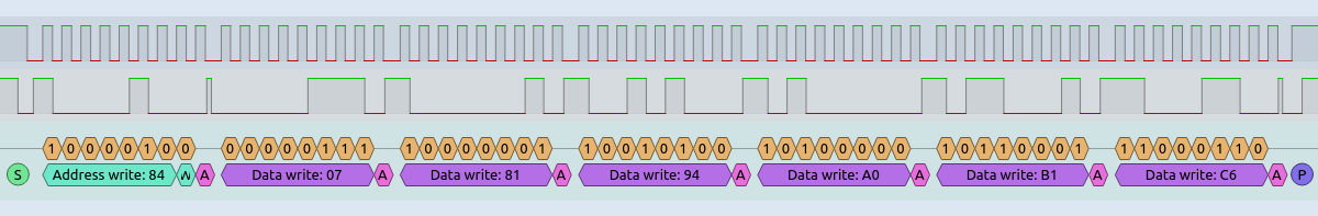
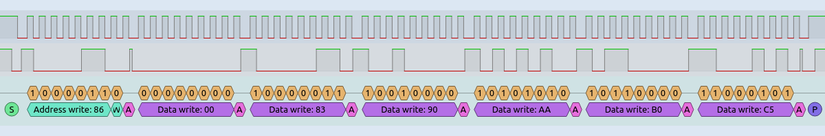
Functions for I2C are used. I won't cover these in detail but the sequence of sending the bytes must start with an I2C start sequence, then an address including write request (LSB is zero), followed by the data bytes, then finally an I2C stop sequence.
My bands from 0 to 9 follow the sequence of the EQ band octaves from lowest to highest, but per the datasheet recommendation, best THD performance is achieved by having a different sequence - band 1 being the highest octave, band 2 2nd lowest, band 3 middle, band 4 2nd highest and band 5 being the lowest octave. On my PCB, each biquad cell is configured with the appropriate capacitors and resistors for the sequence mentioned.
So, after sending the volume, I then send the relevant band. For each band sent, the MSB must be set. Bits 4 to 6 identify the band, and bits 3 to 0 are the boost/cut value as already mentioned above. For band 1, just the MSB must be added, therefore: 0x80 + iBands[9].
For TDA7316, only 4 bands are available. The first band 0x80 is not valid for this chip, so just leave it off (band 1 is 0x80).
Performance
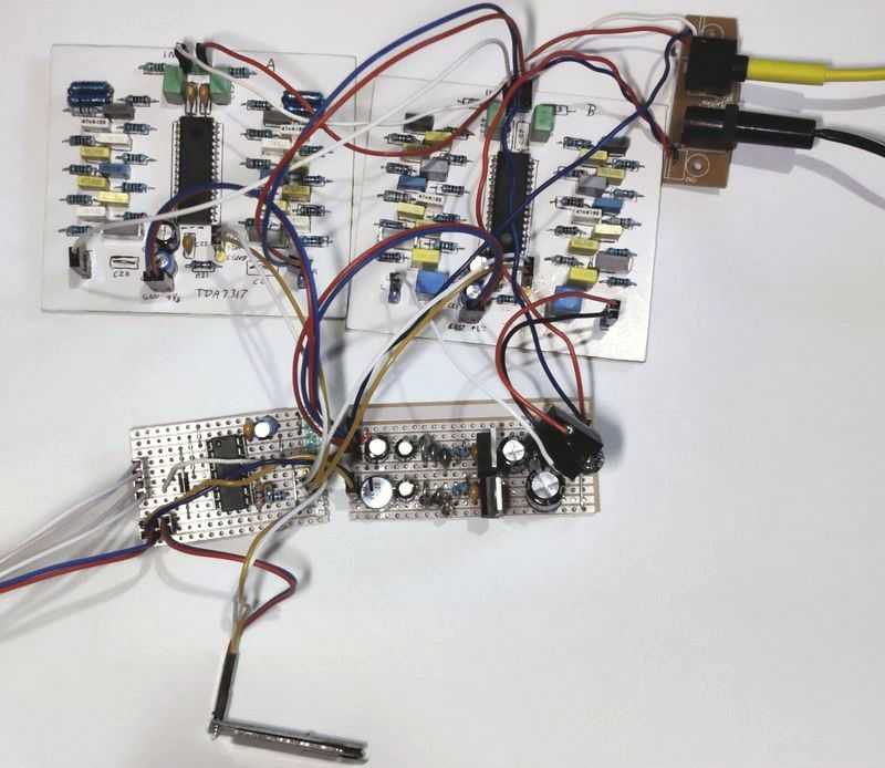
I drilled, drew, etched and soldered two boards for a 10-band stereo TDA7317 equaliser, and another three boards on stripboard for its associated microcontroller, controls and PSU. It was quite some effort, but the result is a fairly small equaliser. You'll need to work out the cost and size benefit vs other solutions to convince yourself.
A fully analogue solution would be superior in audio quality and adjustment resolution (ESP Project 75 is probably the choice I'd make), but you would require many op-amps, potentiometers (either dual or 2x single) and a few more passive components than the TDA7317, so it would be more expensive and more work. A second hand analogue graphic EQ might be a cheaper option.
A DSP system would be likely smaller and superior too but could be very expensive. Free DSP looks interesting though as a DIY option. Still, I think it will still cost significantly more than the TDA7317 + components (but it could certainly do a lot more!), leaving the TDA7317 as maybe the cheapest DIY option.
For battery powered devices, the TDA7317 looks good here as it's low current and would run off 6 to 10V and draw 8 to 20mA. DSP or fully analogue EQ would likely draw more power.
So, the TDA7317 solution is interesting. Sound quality seems fine to me too, though I've not done a blind AB test on my best system. The biggest limitation is the band adjustment resolution - I feel that +/-2dB is way too much jump to do 'proper' Hi-Fi adjustments. It gives more control than standard tone controls (or nothing) though, and can make a Bluetooth speaker, 'midi/mini' system or car stereo a bit more flexible and/or interesting!
It is a discontinued device though, a shame as you'd need to wait for it to arrive from China and take a risk of it not arriving and/or working as expected (my two arrived in a couple of weeks and turned out fine though).
References and more reading:
Source code on github.com
SourceBoost.com for BoostC compiler
PIC Quadrature Rotary Encoder Polling
PIC16F1824 datasheet
TDA7317 datasheet