
PIC Quadrature Rotary Encoder Polling
Quadrature Rotary Encoders - handling and debouncing
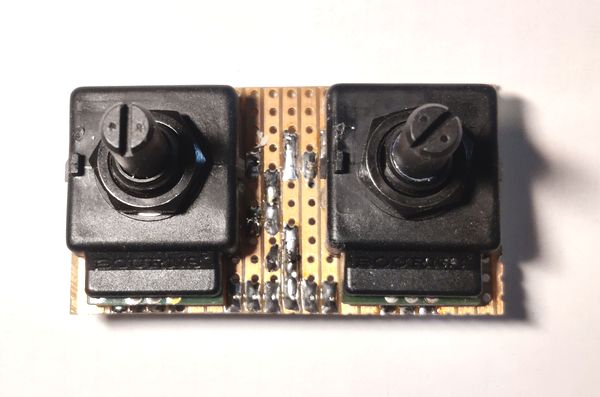
Quadrature Rotary Encoders can be an excellent way of handling user input. In the audio world, for example, they can be used to adjust volume up or down, or change inputs/radio stations etc. My pre-amplifier University project used a rotary encoder for the volume and input selection.
While the code I wrote back then did work, it wasn't perfect. Sometimes turning the encoder clockwise would trigger an anti-clockwise action, especially when the encoder was turned quickly.
I recently built a 10-band graphic equaliser (TDA7317) which used two rotary encoders to select the EQ band to adjust, and make the adjustment boost or cut.
The encoders are mechanical though and suffer with contact bouncing. All mechanical switches will bounce when making or breaking a connection (especially making). For most applications, it does not matter. When connected to a microprocessor though, even a slow one can handle an instruction per micro second (µs) but contact bounce can last a few milliseconds.
This means any polling or interrupt routine is likely to pick up a change in state many times, when really, to us humans, the button push or encoder turn was just once.
Debouncing can be done with hardware or software. With hardware, there are even specific chips to handle debouncing (such as MC14490), or you can use RC filters to smooth the switch transitions. But when you introduce a capacitor across the digital input, TTL inputs will be indeterminate as the capacitor charges/discharges so you must connect to a PIC port that is a Schmitt Trigger or go via a 74HC14 / 74HCT14 Schmitt Trigger Hex invertor chip.
I used the hardware approach in my later pre-amp rebuilds, but I still needed debouncing in code and it still wasn't perfect.
So, I'm sharing my experience and code port of the encoder code handling from Best-Microcontroller-Projects - Rotary Encoder: Immediately Tame your Noisy Encoder.
The "Improved Table Decode Method" is what I built and tested. This requires minimal hardware - you can connect the A and B encoder outputs directly to your PIC input ports with pull up resistors (10k to 100k) or configure the PICs internal pull up if your available input ports include them.
After a small adjustment to handle my encoder noise, I found this code works perfectly and the encoder turns in either direction are correctly identified, and the result is only executed once per detent (which is correct).
Connection / Schematic
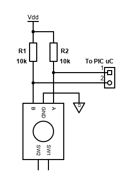
Connecting an encoder to the PIC microcontroller is easy when using software debouncing and decoding like this. Simply ground the middle common pin of the encoder and connect the A and B outputs to the PIC.
If you are connecting to pins that do not have internal weak pull-up resistors, you can use external resistors to VDD.
This allows the input to the PIC pin to be logic 1 when the encoder outputs are off (open circuit). When the encoder is turned clockwise, for example, output A will close to ground, followed by B, then A is opened again, followed by B.
Variables
In the header (.h) file, add some variables:
// valid movements for rencPrevNextCode = 1,2,4,7,8,11,13,14
rom char *rencTable[] = {0,1,1,0,1,0,0,1,1,0,0,1,0,1,1,0};
static unsigned char rencPrevNextCode = 0;
static unsigned char rencStore = 0;
The example below is for handling two encoders. Arrays are used to hold the states of both encoders separately. For three or more encoders, just increase the size of the array.
// valid movements for rencPrevNextCode = 1,2,4,7,8,11,13,14
rom char *rencTable[] = {0,1,1,0,1,0,0,1,1,0,0,1,0,1,1,0};
static unsigned char rencPrevNextCode[] = {0, 0};
static unsigned char rencStore[] = {0, 0};
Initialisation
At initialisation, you just need to think about your port configuration. The relevant TRIS register needs to have the port configured as an input.
If you are directly connecting the encoders without a pull-up resistor, you should set the internal pull-up during initialisation too. Some input pins may not have them, so watch up for that.
If your input is an ADC or other peripheral - you also might need to disable those too, so that the pin can be used for general digital I/O.
In this initialisation, my two encoders are on PORTA.
Encoder one is connected output 'A' to RA2, 'B' to RA3. Encoder two is connected output 'A' to RA4, 'B' to RA5.
/***********************************************************************************
  Function called once only to initialise variables and setup the PIC registers
************************************************************************************/
void initialise() {
    ... snip ...
    // IO ports setup
    trisa = 0x3C; // RA2, RA3, RA4, RA5 are inputs
    porta = 0x00; // set to off
    ansela = 0;
    wpua = 0;
    anselc = 0;
    wpuc = 0;

    option_reg.NOT_WPUEN = 1; // Port A pull-ups disabled - enable if not using an external resistor
    ... snip ...
}
Check encoder code
The check encoder code is below.
The variables rencPrevNextCode and rencStore are global. The encoder state needs to be shifted in to the right of rencPrevNextCode correctly though, with output A of the encoder being the least significant bit.
In this example, output A is connected to pin RA2, and B to RA3. So, I shift the porta variable two to the right so that bit 0 represents the A output and bit 1 represents the B output. This is done with: (porta & 0x0C) >> 2
If your encoder is connected to non-adjacent pins on the PIC microcontroller though, you can just read the bits needed and set the bits 0 and 1 of
rencPrevNextCode appropriately:
char readPortA = porta;
rencPrevNextCode.0 = readPortA.2;
rencPrevNextCode.1 = readPortA.3;
I also found while testing my encoders did not respond with an anti-clockwise direction. To figure out why, I modified the routine to send out rencStore if it was not 0xFF. I sent it via I2C and read it with a USB Logic Analyser. UART or SPI could also be used for debugging.
I found out the state never reached 0x2B, but it did consistently reach 0x2A, so I used this with my encoders. Yours may be different so start with 0x2B and adjust if required.
The method returns 0 if the encoder is not moving, or an invalid/bouncing result. 1 is returned for a clockwise turn, and 2 for an anti-clockwise turn.
/***********************************************************************************
  Rotary encoder turned
************************************************************************************/
char encoderCheck() {
    char returnDirection = 0;
    rencPrevNextCode = rencPrevNextCode << 2;
    rencPrevNextCode |= (porta & 0x0C) >> 2; // For encoder connected to RA2 and RA3 - boolean AND bits 2 and 3 (0x0C), then shift 2 bits right
    rencPrevNextCode |= (porta & 0x30) >> 4; // For encoder connected to RA4 and RA5 - boolean AND bits 4 and 5 (0x30), then shift 4 bits right
    rencPrevNextCode &= 0x0F;

    // If valid then store as 16 bit data.
    if (rencTable[rencPrevNextCode]) {
        rencStore = rencStore << 4;
        rencStore |= rencPrevNextCode;

        // 0010 1011
        //if (rencStore == 0x2A)
        if (rencStore == 0x2B)
            returnDirection = 2;
        // 0001 0111
        if (rencStore == 0x17)
            returnDirection = 1;
    }

    return returnDirection;
}
This alternative can handle more than one encoder. It copies the global variables which are held in an array locally and puts them back into the global array if needed:
/***********************************************************************************
  Rotary encoder turned
************************************************************************************/
char encoderCheck(char in, char encoder) {
    char returnDirection = 0;
    unsigned char lPrevNextCode = rencPrevNextCode[encoder];
    unsigned char lStore = rencStore[encoder];
    lPrevNextCode = lPrevNextCode << 2;
    lPrevNextCode |= in;
    lPrevNextCode &= 0x0F;
    rencPrevNextCode[encoder] = lPrevNextCode;

    // If valid then store as 16 bit data.
    if (rencTable[lPrevNextCode]) {
        lStore = lStore << 4;
        lStore |= lPrevNextCode;
        rencStore[encoder] = lStore;

        // 0010 1011
        //if (lStore == 0x2A)
        if (lStore == 0x2B)
            returnDirection = 2;
        // 0001 0111
        if (lStore == 0x17)
            returnDirection = 1;

    }

    return returnDirection;
}
Main loop
Here is a basic main routine, with no other code or task scheduler. It just constantly runs the encoderCheck routine.
/***********************************************************************************
  MAIN PROGRAM
************************************************************************************/
void main() {
    initialise();

    while (1) {
        actionRotary1(encoderCheck());
    }
}
For checking two or more encoders, the encoderCheck function needs to be given the port result pins, with A and B shifted to the two least significant bits.
/***********************************************************************************
  MAIN PROGRAM
************************************************************************************/
void main() {
    initialise();

    while (1) {
        actionRotary1(encoderCheck((porta & 0x0C) >> 2, 0));
        actionRotary2(encoderCheck((porta & 0x30) >> 4, 1));
    }
}
The actionRotary1 function can be coded to do whatever you need with the result from encoderCheck - 1 for clockwise, 2 for anti-clockwise, or 0 for no-change (which will be most of the time).
Conclusion
The whole code for one encoder in a basic program that increments/decrements a variable will consume around 130 words of ROM and 26 bytes of RAM on a PIC16. For two encoders, around 220 words of ROM and 36 bytes of RAM.
This code usage should leave plenty of room in most PIC microcontrollers for the rest of the code. If it doesn't, consider hardware debouncing instead, but for a hobby project it's likely to be simpler and still cheap to just buy a larger microcontroller than buy the components and design the PCB required for a good hardware debounce.
References and more reading:
Various PIC datasheets
Best-Microcontroller-Projects - Rotary Encoder: Immediately Tame
your Noisy Encoder
Source Boost Technologies