
PIC Microchip DS18B20 Thermometer with 4-digit display
I wanted a smallish, easy to read thermometer for the room we keep some gerbils and a hamster in so we can check it's not too cold for them.
Sure, I could buy one very cheap, but looking through my parts collection, I literally had everything I need to build a thermometer anyway, so I thought it would be an interesting project to build and write up.
Recommended Experience : Intermediate, knowledge of programming, microprocessor programmer, custom PCB used
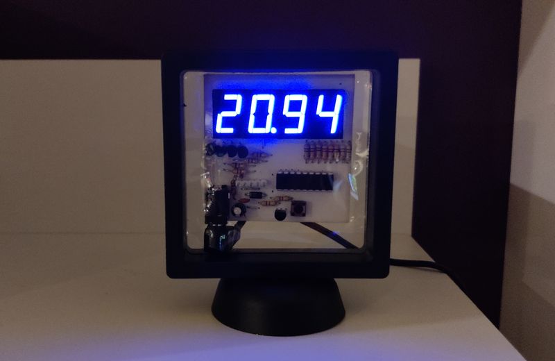
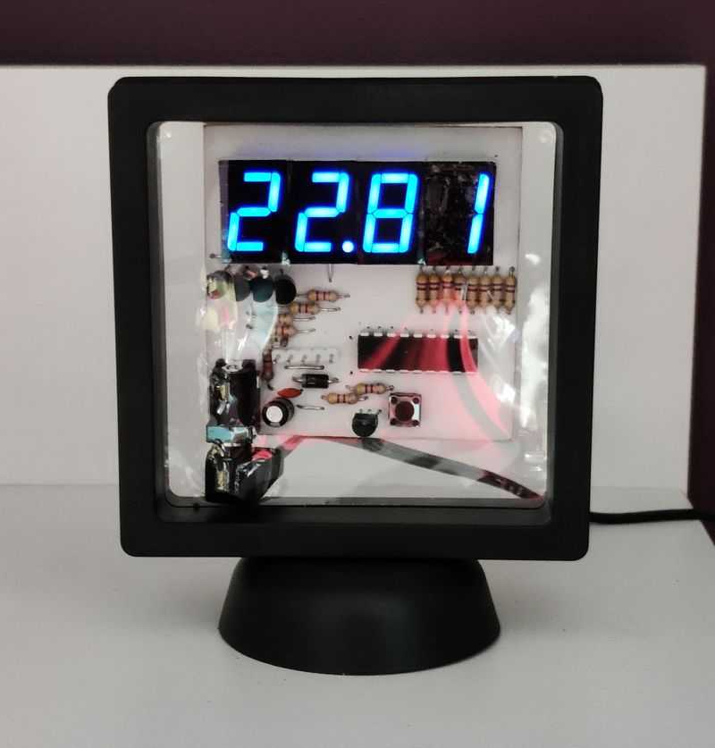
Above: View of thermometer operating
Hardware
The hardware was going to be coming from my parts collection, so I didn't have to order anything at all and proceed immediately with the project.
The components I selected are:
- PIC16F628A - a mid-range PIC that I had, which has 2K words of flash program memory, can run up to 20MHz and has 16 I/O pins.
- DS18B20 - a digital thermometer in a small TO-92 package
- Four 7-segment LED displays, which I had (common anode)
- Four 2SA1015 PNP transistors for Multiplexing the common anode displays
- 8x 470 ohm, 6x 4k7 ohm, 1x 1k ohm - cheap 5% carbon resistors
- 1x 10uF electrolytic capacitor, 1x 100nF ceramic capacitor
- Schottky diode and a signal diode
- tactile push-to-make button
- 5-pin header for ICSP (in circuit serial programming)
- 2-pin DC power connector
- An old 5V 1A DC adaptor from a bygone network router or switch
The hardware is very minimal as most of the work would be done in software on the microprocessor. I picked a PIC16F628A as the most suitable component from the collection I have, although a PIC16F627A would also be fine as the assembled program uses just less than 1k of flash words.
I do have a PIC16F84A too, but I didn't consider this as it has no internal oscillator, and the external crystal would mean there was not enough I/O pins to drive the display directly.
The DS18B20 I brought recently for another project and brought spares. This is a small thermometer which needs only three pins (positive, negative, and a digital I/O pin).
Warning: - the DS18B20 is widely faked. I did purchase a couple off eBay and whilst the first one I tested was fairly accurate, the second was reading almost 3 degrees Celsius lower! I suggest you buy them from well-known retailers, even though they are significantly more expensive, you'll get thermometers which are far more accurate.
The LED display I brought in error years ago but thought this would be a good project to use them. They are a decent size, easy to read, and a nice blue colour instead of the standard red. It's common anode, but if I were purchasing a display specifically for this though, I'd go with common cathode instead, and buy a display that has all four digits in one module rather than four separate ones.
The rest of my parts were just simple transistors, resistors, capacitors, diodes and headers. Most of them came from a years old 'lucky dip' electronics collection purchase I made back in the early 00's, meaning most components are from the 90's or even 80's. Even if buying new though, these components would be cheap.
The tricky part for a novice hobbyist though would be the PCB. The PCB is designed, drawn and etched myself. It's small and designed to fit a display stand.
The whole lot operates off 5V and although I've not measured, the PIC running at 4MHz, multiplexed display and DS18B20 will all need only milliamperes of power, so pretty much any 5V adaptor will work, or USB. Batteries would be possible too (4.5V), though it would not compete with LCD alternatives.
The assembled board is placed in a cheap coin display case which was modified with screws so it sits straight instead of at 45 degrees. Two layers of sticky back window tinting was cut and used to mask the 7 segment displays.
Schematic and PCB
Below is a schematic of the complete solution. It's been oriented and laid out to aid with the PCB design rather than being super clear.
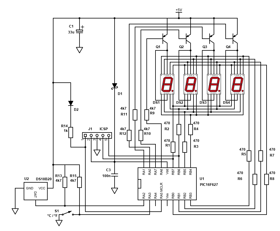
The schematic is quite simple really, although there are a lot of connections especially around the display.
The display is connected to the PIC in two ways:
- The two common anodes of each display to the PIC via transistors. 4 pins at the PIC.
- The cathodes of each segment to the PIC. Each display shares the same connection with the PIC so 8 pins at the PIC are needed (instead of 32)
The first set of connections is the common (COM) connections each display (digit) which are connected via PNP transistors at the top right of the schematic. Each display has two COM ports, which are the anodes of all the LED segments in the display. Both COM ports need to be connected to the collector of the PNP transistor. The emitter of the transistor is connected to +5V, and the base is connected to the PIC pin via a resistor (4k7 will do).
The second set of connections is the cathodes of each display segment diodes. There are eight of them for each display (7 segments, plus the dot indicator).
Since there's 4 displays, so that's 10 pins per display (8 cathodes, 2 anodes), 40 pins to connect in total. We don't need 40 connections to the microprocessor though as the display is multiplexed. 12 connections are needed instead (7 segments, 1 dot, plus 4 connections to the each of the common anodes of each display via transistors).
Each of the segment cathodes are daisy chained to each display (connected in parallel). To avoid lots of jumpers I'd otherwise require on a single layer PCB, I decided to reverse the connections for each adjacent display so I could easily connect one display to the other by drawing the PCB traces in a kind of rainbow layout.
This means the first and third displays would have different segments active from the second and fourth displays. This is purely to ease PCB layout, and also to ease the layout the segments are then connected to the PIC ports in a seemingly random order, but just ensures I don't have traces crossing each other so that I don't have to drill holes and solder jumpers.
If buying a dedicated module with 4 digits integrated, this would simplify the layout further and avoid this. I wanted to use my displays though as well as keep the PCB layout simple. The segments to light for each number is easily defined in the software.
The displays are activated by PNP transistors. During multiplexing, only one display is active at a particular moment. The below gif animation shows how the outputs are scanned to display 4321 on each of the displays. Red is the positive potential difference and green is the negative side.
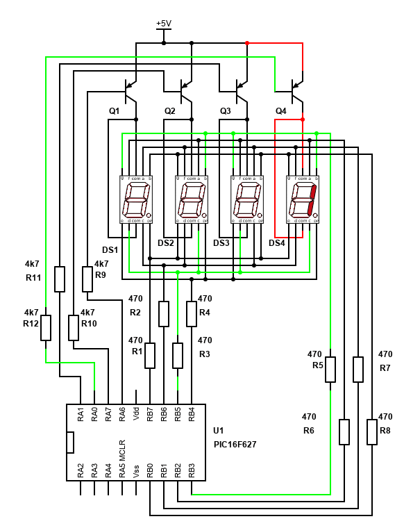
PNP transistors are used because when some or all segments on a particular display are active, it's too much current to drive and sink on the PIC pins directly and the microprocessor would immediately or eventually fail. The transistors however can handle that current. As my display is common anode, a PNP transistor is the best choice. NPN would be the choice for common cathode displays.
The PNP transistor behaves as a switch and will allow current to flow from its emitter to its collector when the base is low/ground. A 4k7 resistor between the transistor base pin and the PIC port ensures the current is limited to the PIC.
The rest of the component arrangement is simple. The ds18b20 chip is wired to Vss (5V), ground and pin RA2 of the PIC. It needs a pull up resistor on the data line to Vss.
A tactile momentary push to make switch was included for selection between Celsius or Fahrenheit and this also include a pull up resistor, though I'm not using this currently.
For programming, since I soldered down the PIC, I included an ICSP header. This allows me to easily plug in my UsbPicProg programmer via a Dupont connector and burn the program onto the chip. This is because there's no chance I'd get the program right first time, and I ended up needing I'd say about 30 to 40 program attempts, so having the header was very useful!
The header does need some extra components itself though. Mainly it needs two diodes so that during programming, the rest of the circuit is not driven. The Schottky diode D1 ensures that the 5V from the programmer isn't driving the LED display or the ds18b20. The signal diode D2 is also ensuring that the (approx.) 13V from the programmer also isn't driving the LED display or the ds18b20 via the 1k resistor R14.
I initially left off D2 but found the programming was failing, and two segments of two displays flickered during the programming attempt. Adding D2 fixed this and prevented the displays from stealing the PGC/PGD signals.
Finally, a DC power connector was included so I could power the project from an old ethernet router PSU (5V 1A). It would also have worked fine off a USB cable/psu too though. The 5V in is decoupled with a 33uF capacitor (I've shown 47uF on my layouts, but anything 10uF or more is fine).
PCB
The PCB was designed by myself, using the techniques I've done for years (see my PCB building guide here). The design was pretty much perfect except for adding in D2 later, which was easy enough to mod.
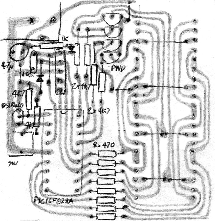
This is my hand drawn style, viewed from the top. It can simply be reversed and drawn as a copy onto single sided copper board. The DPI of this image should print to the exact size needed, which is 58mm x 59mm. It's single sided for build simplicity, and this layout was really the driver of the design, i.e., the software would bend to it! I wanted to minimise the used of jumpers, for aesthetic and build simplicity, but four are still needed on the visible area of the board, and a further six under each display. The jumper lengths are all short and easily made from the offcuts of the resistors.
The design took a couple of hours and replicating it onto the actual board and etching it took another couple, but I'm happy with how it turned out.
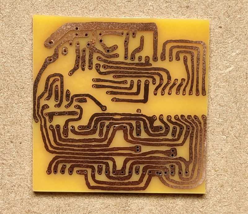
Above: Thermometer PCB etched result
I did make a small mistake when replicating the design and missed a trace. This I corrected by soldering single core wire onto the back of the PCB once I realised the error (the blue wire seen below) - a slightly ugly solution, but one that will work fine. The only alternative would be to redo the whole board otherwise.
A tricky point is the alignment of the holes, particularly the LED displays. All 4 displays I wanted tight against each other and aligned. Sadly, it did not work out this way, but it wasn't far out and enlarging some holes from 0.7mm to 1mm ensured I could position the displays to an acceptable alignment, and still solder the pins to the board.
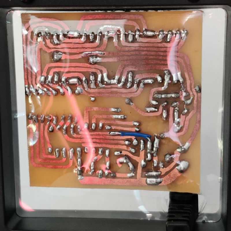
Above: Soldered PCB back as viewed when in the case
Software
PIC microprocessors are 'supposed' to be programmed in its assembler language. Though I have done it before, I find it time consuming and hard to pick up, read and adjust later. Instead, I use C, and since 2005 SourceBoost has been my favourite product for PIC programming.
SourceBoost is now free (donation recommended), though I brought a license a long time ago. Their Chameleon compiler is also free, though I use BoostC and this program easily falls under the 2k limit of the free license.
My source code is available on github.com.
Most of the hard work in this thermometer is in the software. Having it in C allows me to easily code the solution and follow that code when it's not behaving!
There are two main activities the code needs to do:
- Constantly refresh the 4 digits of the 7-segment displays (multiplexing)
- Ask the ds18b20 to do a temperature conversion, read the result after, and convert the result to display
Each of these ended up being quite tricky.
LED 7-segment display / Multiplexing and Timer 0
The gif above shows how the multiplexing works. When you do this at a rate of 60Hz or faster for all displays, they appear to be all lit to the human eye.
As I've got four displays, the rate to refresh each needs to be at least 240Hz. Too fast though and the display won't be lit at all.
I decided to use the timer as a routine to refresh the displays. This removes the need to implement blocking delay routines. Timer 0 can be set to refresh at 244.14 Hz (every 4.1 milliseconds) just by setting the prescaler to 16. This can then flag the main routine to update the display.
    // Setup timer 0, used to flag the 7 segment display to refresh a digit - 4ms timer0 works best
    // https://fsimdeck.wordpress.com/electronics3/led-7-segment-multiplexing/
    // Timer calculator: http://eng-serve.com/pic/pic_timer.html
    // Timer0 Registers Prescaler= 16 - TMR0 Preset = 0 - Freq = 244.14 Hz - Period = 0.004096 seconds
    //option_reg.T0CS = 0; // bit 5  TMR0 Clock Source Select bit...0 = Internal Clock (CLKO) 1 = Transition on T0CKI pin
    //option_reg.T0SE = 0; // bit 4 TMR0 Source Edge Select bit 0 = low/high 1 = high/low
    //option_reg.PSA = 0; // bit 3  Prescaler Assignment bit...0 = Prescaler is assigned to the Timer0
    //option_reg.PS2 = 0; // bits 2-0  PS2:PS0: Prescaler Rate Select bits
    option_reg.PS1 = 1;
    option_reg.PS0 = 1;
    tmr0 = 0; // preset for timer register
    intcon.T0IF = 0; // Clear timer 1 interrupt flag bit
    intcon.T0IE = 1; // Timer 1 interrupt enabled
The displays themselves are driven from twelve PIC pins. The whole of port B (RB0 to RB7) drives the segments, and bits 0, 1, 6 and 7 (RA0, RA1, RA6 and RA7) select the display (digit).
With common cathode displays using NPN transistors, we would select the displays and segments by putting the output high, but with common anode displays using PNP transistors it's the opposite. Therefore, you have to think of ON means OFF and think about how the voltage is flowing.
To drive the segments and activate the correct display, I made three arrays in code. The first is an array to output the correct values on porta in order to drive the correct display (array length of 4). The second and third arrays are collections of values to put on port b for activating the correct segments. These are lengths of 12 - 10 numbers, a minus sign and a blank value. Two different arrays are needed because the pins on the first and third displays are different to the second and fourth.
// array to hold the porta values in order to light the correct display during multiplexing
char arrDigits[4] = {194, 193, 67, 131};

// numbers 0 to 9, blank, and minus sign
// arrays to hold the portb value to light the correct segments on the common anode display connected on portb
// This is 12 length array - 0 to 9 are numbers, 10 is minus symbol, 11 is blank
// display 0 and 2 use this array
char arrSegments0[12] = {17, 215, 50, 146, 212, 152, 24, 211, 16, 144, 254, 255};
// display 1 and 3 use this array
char arrSegments1[12] = {136, 190, 196, 148, 178, 145, 129, 188, 128, 144, 247, 255};
The refreshDisplay() is called by the main PIC routine whenever timer0 overflows (every 4 milliseconds). This increments a counter to identify which digit will be active during this execution. The displayValue() method then takes that active digit value and uses the arrays to translate the value onto the relevant pins of porta and portb.
/*********************************************************************************************
  displayValue(char iDigit)
  Function called by multiplexing
  Used to light one digit out of the four with the correct segments
*********************************************************************************************/
void displayValue(char iDigit) {
    // turn all digits off first
    // add on current bits 2 to 5 of porta to keep their value
    porta = 195 + (porta & 60);
    delay_us(5);

    // get the digit to display
    char cDig = arrTemp[iDigit];

    // Set port b to the correct value
    // Use the array zero for the displays 0 and 2, otherwise array 1
    // Display 0 is the right most display
    if ((iDigit == 0) || (iDigit == 2)) {
        portb = arrSegments0[cDig];
        if ((iDigit == iDecimalPosition) || (iDigit == iTempUnit))
            portb -= 16;
    } else {
        // minus 128 (rb7) to turn the decimal on
        portb = arrSegments1[cDig];
        if (iDigit == iDecimalPosition)
            portb -= 128;
    }

    // Now set porta to the correct value to light the correct digit
    porta = arrDigits[iDigit] + (porta & 60);
    delay_us(5);
}

/*********************************************************************************************
  displayValue(char iDigit)
  Function to perform multiplexing
  Calls displayValue with the digit argument, resets to 0 when the counter reaches 4
*********************************************************************************************/
void refreshDisplay() {
    // if 4, reset to zero
    if (iDigitCounter == 4)
        iDigitCounter = 0;

    // display the digit
    displayValue(iDigitCounter);

    // increment counter
    iDigitCounter++;
}
As an example, to show the value '1' on the first display (first being the one on the right), initially porta needs to be set wholly high, deactivating all the displays. The value 195 (1100 0011) is added on to the existing values of porta. This switches off the PNP transistors.
Next the segments will be prepared. Port B needs to be set appropriately for the display that is active (in this case 0) and the segments required - those being b and c.
For display 0, segments b and c are connected to RB3 and RB5 respectively. The value of 215 (1101 0111) is read from the array arrSegments0, position 1 (since we're display the number 1). As can be seen, the 3rd bit (4th number from the right) and the 5th bit are 0. This will cause the PIC to make the output voltage 0V for these pins, allowing the current to flow through the display. The rest of the pins are at 5V so no current will flow (5V - 5v = 0V potential difference) for the rest of the segments.
To display the dot on a display, an arbitrary value is added (actually subtracted) to the port b output in order to light the dot. Although it can move, there's only ever one dot active on the display, so I used a variable to choose the display number that would be. To display the dot on the first display in the example above, as the dot is connected to rb4, the value of 16 (0001 0000) is taken off the value returned from the array (result would therefore be 199, in binary 1100 0111).
DS18B20 and the Dallas/Maxim One-Wire Protocol and Timer 2
The DS18B20 is a simple and small thermometer. It fits in a TO-92 package (or even smaller ones) and looks like a three-pin transistor.
Three pins certainly simplifies the hardware set up and PCB design. It can even be driven with two wires only (ground and data, aka parasite power), but this complicates the software.
So, to include it in your schematic and PCB design, all you really need to think about is GND going to your digital ground plane/bus, VDD going to the power supply (which can be 3V to 5.5V), and DQ going to a free pin on your microcontroller with a single pull up resistor to VDD of 4.7k ohms. I suggest VDD to ground is decoupled with a 100nF to 1uF capacitor if the DS18B20 is some distance from the rest of the microcontroller circuit, but on my board that's not a problem.
The pin on the microprocessor must be capable of being both input and output. This is because of the one-wire serial bus that will be used to communicate with the DS18B20.
The one-wire bus is a little tricky... I'd say for me trickier than I2C or SPI protocols because there is no separate clock signal to shift bits in/out. To deal with the lack of clock, the one-wire bus relies on the bus being driven low to signal points in the communication, and when transferring binary, it relies on timings of the signal... a bit like RS232, but without all the extra bits and obviously no separate receive and transmit bus.
It's easy to think of the bus in separate states:
- Floating, which is logic high as the bus is pulled high by that 4k7 resistor
- Driven low (0V) by either the lead microcontroller or the DS18B20 itself
During the communication, only one device can drive the bus at one point. The leader microcontroller will start it, but then delays are needed in order for the DS18B20 (follower) to pull the bus low to either acknowledge a command or send binary zero. For me, getting this timing right was a challenge, not helped by delay_us code routine being a bit inaccurate when delays are tens of microseconds (delay_10us solved this).
As the display is multiplexed, I need to keep the one-wire communication as short because the PIC is not multithreaded and when it is carefully running and timing the one-wire communication, it cannot multiplex the displays and vice versa. Therefore, my delays are on the shorter side in my code. Still there is some flicker visible on the display when temperature readings are asked for, but it's not hugely distracting.
I used my Logic Analyser with Sigrox PulseView in order to monitor what was happening on the one-wire bus and adjust my code to suit the timings.
The one-wire bus allows for more than one DS18B20 device on the same bus, so you could have two or more thermometers all in parallel with each other, sharing the same GND, DATA and VSS lines, but in different locations.
I only have one though, so for this code, my lead microcontroller will address all devices on the bus, and since only one will respond it can read the data directly.
The DS18B20 communication is done in three steps, which is repeated every time I want to update the thermometer reading.
- Initialisation - send a reset pulse, and wait for the presence signal
- Send command CONVERT T [0x44] - this tells the follower DS18B20 to make a temperature reading
- Send command READ SCRATCHPAD [0xBE] - after 750ms, ask the DS18B20 to send its ROM values. The first two bytes returned contain the temperature
Initialisation and sending two bytes for the convert command is shown with the timing diagram below.
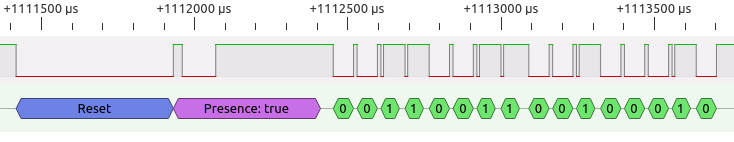
The reset pulse is done by my lead PIC software setting its pin as an output and pulling the pin low. This is done by clearing the relevant bit in TRISA and PORTA (or TRISB/PORTB etc if the DS18B20 is elsewhere). This needs to be 480us (microseconds) at least. I went with 500us, and measured 534us in PulseView (this will be the overhead of instructions on the slow 4MHz PIC).
The DS18B20 responds pretty quickly after 30us measured, but for safety I check after 70us. I measured the acknowledge response to keep the bus low for 109us, but it can be 60us to 240us. The total time for the presence/acknowledge pulse should be a minimum of 480us. A timer2 interrupt is used to time 500us on the initial reset pulse, and the presence pulse, before bits are transmitted.
Timer2 was used in order for the long reset routine delaying the multiplexing on the display. This means that once the reset pulse is sent, instead of having a blocking delay routine for 500us, a timer is started, and the PIC can do other work until the timer fully counts to 500us and causes an interrupt.
In order to handle this correctly, there are three methods. The first oneWireBusReset() generates the start of the reset pulse by pulling the bus low.
This will then call oneWireBusResetTimerStart() which will reset timer2 and configure it to interrupt once it reaches 500us.
The oneWireBusReset2() is called after that first interrupt. This does the bus release and check for the ds18b20 presence signal. Then it starts the timer again using oneWireBusResetTimerStart(). Once the timer interrupts a second time, the main routine will then move on to calling the transmit byte methods.
/*********************************************************************************************
  oneWireBusResetTimerStart()
  Resets and starts timer2, which will interrupt after 500us
*********************************************************************************************/
void oneWireBusResetTimerStart() {
    pr2 = 250;
    cTask.TASK_TIMER2 = 0;
    t2con.TMR2ON = 1;
}

/*********************************************************************************************
  oneWireBusReset()
  First part of the reset routine - drive the bus low for 500us
*********************************************************************************************/
void oneWireBusReset() {
    char isPresent;
    oneWireTris = 1; // start with high
    isPresent = 0;
    // Send the reset pulse - drive low for 500us
    oneWireBus = 0;
    oneWireTris = 0;
    //delay_10us(50);
    oneWireBusResetTimerStart();
}

/*********************************************************************************************
  oneWireBusReset()
  Second part of the reset routine, check for presence pulse, and wait a further 500us
*********************************************************************************************/
void oneWireBusReset2() {
    // Called after timer2 counts 500us
    // Release line and wait 70us for PD Pulse
    oneWireTris = 1;
    delay_10us(7);
    // Now sample, if there is a sensor on the bus, the line should be low
    if (oneWireBus) {
        oneWireIsPresent = 0; // no devices
    }
    oneWireBusResetTimerStart();
}
After the unique reset pulse, the next set of communication is leader microcontroller writing bytes to the DS18B20.
/*********************************************************************************************
  oneWireTxBytes(char data, char data2)
  Transmits a 2 bytes from the bus
*********************************************************************************************/
void oneWireTxBytes(char cData, char cData2) {
	  // Reset first - done in main
	  //oneWireBusReset();
	  // Send first byte
	  oneWireTxByte(cData);
	  // Send second byte
	  oneWireTxByte(cData2);
}
To write bytes to the DS18B20, the lead microcontroller controls the bus only. It must pull the bus low, and then either release it within 15us to write bit '1', or keep it held low for at least 60us to write bit '0'.
/*********************************************************************************************
  oneWireTxByte(char data)
  Transmits a single byte from the bus
*********************************************************************************************/
void oneWireTxByte(char cData) {
    char cTemp = 1;
    // Loop through the eight bits in the byte
    for (char i = 0; i < 8; i++) {
        // Send the LSB first

        // Drive the line low initially for 3us
        oneWireTris = 0;
        oneWireBus = 0;

        // Delay not needed for 4MHz PIC
        //delay_us(3); // Delay 3us

        if (cData & cTemp) {
            oneWireTris = 1; // Release the bus
        }

        delay_10us(5); // Delay 60us - 50us works fine with code delays
        oneWireTris = 1; // Release the bus

        // move the test bit
        cTemp <<= 1;
    }
}
Since the PIC is running at a slow (but power friendly) 4MHz, for writing '1' the bus is released immediately in code after pulling it low. The 'if' instruction in between pulling the bus low and raising it again is enough to hold the bus low for 6us, and the DS18B20 successfully detects that. In both '1' and '0' bits, the line is either kept low or released for 60us. With the overhead of instructions though the window is 78us before the next bit is sent. That's close to ideal as each write bit time slot should be at least 60us + 1us recovery time.
The bits in each byte are sent from the least significant bit (LSB) first, so in the example above the bits detected as 00110011 should be read as 1100 1100, or 0xCC in HEX. This is the first command, which means Skip Rom - address all devices. The cTemp is a test byte which starts with the LSB set, and the bit is moved to the left each time the loop runs. When doing a logical AND with this test byte and the data byte, the routine knows whether to send '1' or '0' down the bus.
The second bit is 00100010, read as 0100 0100 or 0x44 in HEX. This is the second command, meaning Convert T. The two bytes sent I measured as taking 2ms (milliseconds) in total.
After a delay of 750ms, which is measured by the PIC timer1 instead of blocking the main code execution, the temperature is read.
A reset pulse and then another two bytes are sent from the leader PIC, the same 0xCC command, then the 0xBE command which is the read scratchpad. Then we come on to reading...
Once the DS18B20 receives the 0xBE command, it will prepare itself to send the data out from its SRAM (the scratchpad). Each bit is sent, LSB first again, but the BS18B20 will only send the bit if it detects the leader PIC is ready to receive it. The send this notification, the PIC will drive the bus low, but then release it again. This happens immediately in my code, measuring 4.5us. It only needs to be at least 1us.
Once that happens, the DS18B20 will then either drive the bus low itself, or release it. The PIC then checks the status of the bus 6us after releasing it and will read the bit as '1' if the bus is high, or '0' if the bus is low. The bit is shifted into a byte from the right and then the routine is held for 60us to ensure the read time slot is safely passed before starting the next one. The read slot in total only needs to be at least 60us. With all the code together, it measures 92us per bit.
Bits are received from the ds18b20 LSB first. The cDataIn variable initially starts at zero. During each loop execution, the bits are shifted left, and if the ds18b20 is sending a high bit on the bus, the MSB (bit 7) in cDataIn is set. So, if the LSB is sent first, bit 7 (MSB) is set on the first iteration of the loop. The next iteration will move that bit to right each time, so once the loop runs eight times, the MSB is now the LSB, and each subsequent bit is filled in from left to right.
/*********************************************************************************************
  oneWireRxByte()
  Receives a single byte from the bus
*********************************************************************************************/
char oneWireRxByte() {
    char cDataIn = 0;
    // Loop through the eight bits in the byte
    for(char i = 0; i < 8; i++) {
        // Bring bus low for 15us
        oneWireTris = 0;
        oneWireBus = 0;

        // Delay not needed for 4MHz PIC
        //delay_us(15); // Delay 15us

        // Release bus for 6us, this is enough time for the slave to respond
        oneWireTris = 1;
        delay_us(6); // Delay 6us

        // Shift data already received left
        cDataIn >>= 1;
        // Check the value of the onewire bus - set the MSB of cDataIn if so
        if (oneWireBus)
            cDataIn.7 = 1;

        // To finish time slot
        delay_10us(6); // 60us
    }

    return cDataIn;
}
Getting the timings right was tricky. The onewire.h library included in BoostC did not work for me, and nor did various examples online, though I've referenced them below as they certainly helped. Reading the DS18B20 datasheet carefully though provides lots of help.
Shown by the pulseview capture, the bits returned are 0110 0010 and 1000 0000. This is LSB, with the low byte coming, so translated its 0000 0001 0100 0110 (1 and 70, or 326). Divided by 16 gives the actual temperature in Celsius - 326/16 = 20.375 degrees.
Translating the temperature
Dealing with division, floating point numbers, or even numbers longer than 8 bits is tricky in a PIC. It can be done, but not natively in assembler and with C the assembler code generated is large. The number above can also negative (using two's complement).
Whilst I initially ended up writing my own function to carve up the bytes and convert it into absolute integer portions and round appropriately, I struggled to do this and allow Fahrenheit conversion.
Therefore, I decided to stick with the math over 16-bit signed integers. The code is simple in C, but the generated assembler is fairly large.
For simplicity, temperatures over 99 degrees are not supported. I'm unlikely to use it in these temperatures and the components I've used probably have no better than 85 degrees rating anyway.
Negative temperatures are supported though. The left most display will display a minus sign in this case. From -9.99 to 0, two decimal places can be displayed, but for -10 and lower though, only one decimal point is supported.
Fahrenheit is displayed with only one decimal place.
I came across two great pieces of code from two different places online (see references below and in the code). One will take the ds18b20 reading and convert it to Celsius multiplied by 100. This is quite simply (6 * iTemp) + (iTemp / 4) - and it works perfectly. Because there is multiplication and division there, the assembler generated is pretty large (PIC16 does not have multiply and divide instructions), however it's not much larger than my original method. The division by 4 is simple enough because it is the same as shifting the bits two to the right (and the BoostC compiler detects this).
As an example, if the ds18b20 read 20 Celsius, it would return 320 (0000 0001 0100 0000). (6 * 320) + (320 / 4) gives 2000 (actual temperature times 100). For 20.5, 328 is read, and the result is 2050. If a 20.125 is given, 322, it will return 2012. The decimal place is truncated, so it's not perfect (should be 2013), but good enough.
The Fahrenheit conversion is a similar piece of maths requiring division. It is ((iTemp + 4) / 8) + iTemp + 320. The division is the same as shifting the bits three to the right, but this piece of math does need to operate on the signed short integers and is designed to give a signed result.
In the same example, if the ds18b20 read 20 Celsius, it would return 320. ((320 + 4) / 8) + 320 + 320 gives 680.5, or 680 on the microprocessor because the decimal is truncated. It's really close to the real conversion, in this case perfect (20 * (9/5))+32 = 68°F.
My store temp function uses both of these techniques, depending on the temperature to display. It does this:
- Takes the upper and lower bytes returned from the ds18b20 and create a signed integer number from them. Assumes the decimal place is in the middle to begin with (2)
- If the iTempUnit is set, then do Celsius conversion
- Get an absolute value of iTemp first by applying two's complement logic to the number if it is minus
- Perform the Celsius conversion (6 * iTemp) + (iTemp / 4)
- Split the digits
- If the temperature is -10 or lower, shift the digits to the right (this will truncate the second decimal place)
- If the temperature is negative, put a minus sign in the left most digit
- If the iTempUnit is clear, then do Fahrenheit conversion
- There is only one decimal place in this conversion, so move the decimal
- Perform the Fahrenheit conversion ((iTemp + 4) / 8) + iTemp + 320
- Get an absolute value of iTempF (the converted result) by applying two's complement logic to the number if it is minus
- Split the digits
- If the temperature is negative, put a minus sign in the left most digit - this is safe because we'll never get to -100°F
The storeTempDigits4 function is based on more advice found online. This method generates less instructions for the PIC compared to using the divide / and modulus % operators to split the digits up.
/*********************************************************************************************
  storeTempDigits(int iValue)
  Used to split the temperature reading into digits and place on the arrTemp array
  iValue = temperature value part (0 to 9999)
  https://electronics.stackexchange.com/questions/158563/how-to-split-a-floating-point-number-into-individual-digits
*********************************************************************************************/
void storeTempDigits4(int iValue) {
    // simple way, but more program memory needed (more than 100 words more)
    //char cDig3 = iValue / 1000;
    //char cDig2 = (iValue / 100) % 10;
    //char cDig1 = (iValue / 10) % 10;
    //char cDig0 = iValue % 10;

    // less program memory needed - may be slower executing
    char cDig3 = 0;
    char cDig2 = 0;
    char cDig1 = 0;
    char cDig0 = 0;

    // incrementing variables for each digit

    // determine to thousands digit
    while (iValue >= 1000) {
        iValue = iValue - 1000;
        // each time we take off 1000, the digit is incremented
        cDig3++;
    }

    // determine to hundreds digit
    while (iValue >= 100) {
        iValue = iValue - 100;
        // each time we take off 100, the digit is incremented
        cDig2++;
    }

    // determine to tens digit
    while (iValue >= 10) {
        iValue = iValue - 10;
        // each time we take off 10, the left most digit is incremented
        cDig1++;
    }

    // the last digit is what's left on iValue
    cDig0 = iValue;

    // left fill zeroes with blanks up to the digit before the decimal place
    if (cDig3 == 0) {
        cDig3 = 11;
        if ((cDig2 == 0) && (iDecimalPosition == 1))
            cDig2 = 11;
    }
    arrTemp[3] = cDig3;
    arrTemp[2] = cDig2;
    arrTemp[1] = cDig1;
    arrTemp[0] = cDig0;

}
I changed it a little to not need signed numbers, and at the end the digits are left fill a blank, so the number 10 would be displayed as such instead of 0010.
The splitting happens four times. The first (thousands) digit is worked out by taking off 1000 from the value whilst it is greater than 1000. So, if 10 was sent, nothing happens and cDig3 remains as zero. If 1000 was sent though, the loop executes once and cDig3 becomes 1.
The process repeats for 100 and 10. The final digit (units) is just whatever is left on iValue.
The final part will replace the zeros with 11 (my arbitrary value to display a blank digit on the display). The second (hundreds) digit should only be blanked if the first digit was, and only one decimal point is displayed, otherwise if 1000 was sent, we'd display 1 00.
Timer 1
Timer 1 was used for two purposes:
- Counting a delay between asking the DS18B20 to convert a temperature and reading it after (needs to be at least 750ms
- An interval for refreshing temperature readings, which I picked as around 2 seconds
Timer 1 is used because the timer counts as a separate unit in the PIC. Without using this I would have to rely on doing delays in the main execution of the code, which is tricky to do when multiplexing the 7 segment displays at the same time.
You can't get 750ms interrupt from timer1 directly, so the best thing to do is pick a value that divides nicely. On a 4MHz speed and a 1:4 prescaler, timer 1 will interrupt every 262ms. Once the interrupt occurs three times, then more than 750ms has passed (786ms) and the temperature can be retrieved from the DS18B20.
    // Setup timer 1, used to periodically ask for a temperature reading, and receive it after sending - 262ms
    // Timer calculator: http://eng-serve.com/pic/pic_timer.html
    // Timer 1 setup - interrupt every 262ms seconds 4MHz
    t1con = 0;
    t1con.T1CKPS1 = 1;   // bits 5-4  Prescaler Rate Select bits
    //t1con.T1CKPS0 = 0;   // bit 4
    //t1con.T1OSCEN = 0;   // bit 3 Timer1 Oscillator Enable Control bit 1 = off - this should be cleared so we can use RB7 and RB6 as outputs
    t1con.NOT_T1SYNC = 1;    // bit 2 Timer1 External Clock Input Synchronization Control bit...1 = Do not synchronize external clock input
    //t1con.TMR1CS = 0;    // bit 1 Timer1 Clock Source Select bit...0 = Internal clock (FOSC/4)
    //t1con.TMR1ON = 0;    // bit 0 enables timer
    pie1.TMR1IE = 1; // Timer 1 interrupt
    pir1.TMR1IF = 0; // Clear timer 1 interrupt flag bit
This 262ms timer can also be used to periodically refresh the temperature. My preference was every 2 seconds to check the temperature, so I can look and see the temperature changing in pretty much real time. 262ms multiplied by 8 gives just over 2 seconds. Add on the 3 for the 750ms count earlier, and the check is 11 interrupts.
As a tertiary function, timer1 is also used for polling the status of the temperature unit button. At 262ms, that's a bit higher than push buttons are usually polled, but it's still short enough to pick up a button press if the button is pressed and held for a very short moment.
    // Interrupt on timer1 - ask for temperature, get the temperature
    if (pir1.TMR1IF) {
        cTask.TASK_TIMER1 = 1;
        // timer 1 will interrupt every 262ms with a 1:4 prescaler at 4MHz
        // We'll ask for the temperatute every 2 seconds
        // Into 2 seconds, 262ms goes 8 times (roughly)
        if (iTimer1Count == 8) {
            // If the number of tasks to perform is less than the limit,
            // then add this task to the task array
            cTask.TASK_TIMER1_START = 1;
        }
        // just over 750ms after asking for temperature, it should be ready, so get the reading
        // Into 2.75 seconds, 262ms goes 11 times (roughly)
        if (iTimer1Count >= 11) {
            iTimer1Count = 0;
            // If the number of tasks to perform is less than the limit,
            // then add this task to the task array
            cTask.TASK_TIMER1_READ = 1;
        }
        // Count the number of times this timer overflowed
        iTimer1Count++;
        // Clear interrupt flag
        pir1.TMR1IF = 0;
    }
The TASK_TIMER1 flag is set on every interrupt (so every 262ms). This tells the main routine to check for the status of the push button.
The TASK_TIMER1_START flag will ask the startTemp() routine to run, and this is flagged after 8 interrupts (just over 2 seconds). TASK_TIMER1_READ will ask the readTemp() routine to run after 11 interrupts (a bit over 2.75 seconds).
Conclusion
Above: View of thermometer operating in daylight
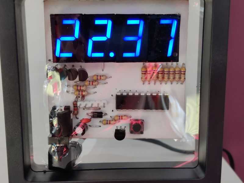
Above: Closer view
That's really all there is to the program. The whole lot uses 746 words of ROM (out of 2048), 64 bytes of RAM (out of 224) and runs successfully from the PICs internal 4MHz oscillator.
This project was supposed to be quick, but I'd say it ended up costing me 5 whole days in total! Overall though I'm happy with it and learnt how to do multiplexing and understand and adjust one-wire communications for the ds18b20, and skilled up a little more on bitwise operations.
The result isn't perfect, as the temperature has rounding errors when the decimal is truncated, and when the temperature is read there is a flicker on the display that even using Timer 2 didn't completely help with. Much of the code would be useful for future projects, as is the knowledge I built up understanding and optimising code, and I'm pleased with the result. Apart from time, there was also no cost to me as the whole project was built from spare parts.
References and more reading:
- Source code on github.com
- PIC16F628A datasheet
- DS18B20 datasheet
- My PCB building guide
- SourceBoost Technologies - low cost, high performance cross compilers
- UsbPicProg - Open Source Microchip PIC programmer
- Dring Engineering Services - IC Timer Calculator and Source Code Generator
- Learning about Electronics - How to Connect a In-Circuit Serial Programming (ICSP) Interface
- FSimDeck - LED 7-Segment Multiplexing
- SourceBoost Forums - DS18B20 one wire reference for SourceBoost
- Peter H. Anderson - DS18B20 SourceBoost implementation, including ds18b20 to Celsius x100
- Electro-Tech-Online - Temperature Sensor DS18B20 Display Fahrenheit, ds18b20 reading to Fahrenheit x10
- Electro-Tech-Online - PIC Single-Chip 4-Digit DS18x20 Temperature Monitor
- Circuit Digest - Digital Thermometer using a PIC Microcontroller and DS18B20