
Raspberry Pi IR and Thermal Camera
In 2020, as a Christmas gift, I requested and received a Pi Zero with No-IR Camera so that I could build a small project to see what the little pets get up to at night.
It took some work, but I got it going with a rtsp stream exposed to my network which I could then use my server to record.
In 2021 I also added a thermal sensor based on the AMG8833 - only 8x8 resolution, but it was all that was affordable at the time, however software is limited and all that I was happy enough with is a Python program interpolating the 64 pixels to something bigger, but it needed an X session and used a lot of CPU.
Fast forward to 2024, I wanted to improve the project - put it in a box and upgrade the OS and upgrade the Pi to the better Zero 2 W (the original Zero W will be re-purposed).
This time I wanted the camera to be natively viewed on a webpage from my phone or any PC, with the option to record. I also wanted an interpolated output of the AMG8833 thermal sensor also available in a web page anywhere. Previously I could only use it via X forwarding.
Ideally, I'd like it to have its own touchscreen too for usability, but having brought one I was disappointed with it (mainly not being able to turn it off, but also its poor refresh rate). We almost always have a good quality touchscreen with us most of the time - our smartphones!
So, here is my implementation:
Hardware
Below is the hardware I'd use for the project:
- Raspberry Pi Zero 2 W - the brains of the operation, a cheap ARM computer developed here in the UK, but has become extremely popular. I need the 'W' version with wireless so I can access the camera streams remotely. Designed to run Linux (and I'll use the default Raspberry Pi OS distro). Requires a separate Micro SD card.
- Raspberry Pi official No-IR Camera - my module is version 2, based on the Sony IMX219 sensor without an IR filter so it can 'see' infrared. A flex cable compatible with the Pi Zero is also required (included one only fits the standard sized Raspberries). If you don't have the camera, I highly recommended buying the v3 module (IMX708) as the quality is much better, and it has autofocus!
- AMG8833 Thermal Sensor - an 8x8 thermal camera that senses temperature. This is the best I could get at the time - MLX90640 is better, and worth it if you can spare more money.
- Infra-red 3W Epistar Bridgelux Epileds LEDs - I used 3x, but it's overkill (I PWM at 20% duty cycle for the right brightness) and one would do. An NVMe M.2 2280 heatsink is nicely sized to git them on to.
- LM2596 Buck Convertor DC-DC Module - for dropping 12V to 5V for the Pi Zero and peripherals.
- LM2596 Constant Current DC-DC Module - for supplying a constant current to the 3W LEDs.
- IRLZ34N MOSFET - switches the LED on/off. Any similar Logic Level N-Channel MOSFET will work.
- 12V DC power supply brick - 2A or better.
- Green LED and 270 ohm resistor, for off-board activity indication.
- 2.1mm DC connector, Micro USB connector (for Pi power), 2.54mm headers for Pi, 'Dupont' connectors and housings (best get a kit), cable, stripboard, nylon screws, nuts, stand offs/mounts.
- ABS case to house it all.
That's it - I decided on no screen or buttons as operation would be performed remotely via a Smartphone or PC (ssh) to make changes, run updates etc.
I also decided on no battery operation as it would be used for long hours when required and the power required to run the IR lights is significant. There is also no microphone, but it would be possible to add a USB one to the spare port if required, via a USB micro to USB A socket extension.
The cameras are the greatest expense for the project, followed by the Pi and LEDs. The rest of the hardware shouldn't add much to the cost but as usual, you'll benefit from buying kits for wires, connectors etc. and keeping spares for other projects (though over years, you do end up like me with a far more than needed parts collection!).
The below wiring diagram is how the hardware is connected together:
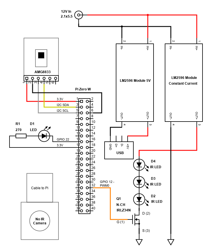
The two LM2596 modules are popular on eBay / Amazon / AliExpress etc. and are very cheap. There are chances of receiving duds (or reports of capacitors on them soldered the wrong way), but generally they are fine for hobby use if you derate them to about 1.5A output max. That's enough to power the Pi Zero with 5V, and the 3x 3W IR LEDs with a constant current.
Both should be powered before connecting to the Pi and LEDs, so that you can set the potentiometers on them correctly. The module powering the Pi only needs one setting to set the voltage output to 5V. You'll need a multimeter on the DC Voltage V ⎓ setting, in parallel with the output (across).
For the power supply to the LEDs, this is a little more complex. You should set the output voltage first. This needs to be greater than the sum of the voltage drops across the LEDs.
My IR LEDs drop 1.8V. There are three LEDs in series, so the voltage drops add together to 5.4V. I set the voltage output to 6V with no load and the multimeter in DC voltage mode in parallel with the output.
Next is to set the current. Each LED has a forward current of 700mA, but I went with 600mA since this will provide close to the same amount of brightness. As the LEDs are in series, the current is the same still, so the LM2596 CC module needs to be set to 600mA. This can be done by using the multimeter in the A or mA setting (A for mine as mA can only measure up to 300mA). By putting the multimeter across the output of the module, this 'short circuits' it, putting it in constant current mode. You can then adjust the potentiometer so that the current measured is 0.6A / 600mA.
If you wish to use a resistor for the LEDs instead to limit the current, this will waste some power due to the high power of the LEDs. But before I received the constant current module, I had success by connecting the LEDs in series with a 12V supply and a series 10 ohm resistor. It will dissipate almost 5W, so get a 7W or 10W wire-wound resistor. Naturally, this will be hot to touch during operation. Make sure your PSU can handle 5W[resistor] + (3*3W)[LEDs] + 6W [Pi]. A 2A 12V (therefore 24W) supply would be enough. Always ensure the power supply can provide more current than you need as the circuit will not be 100% efficient and may have transient current draw too.
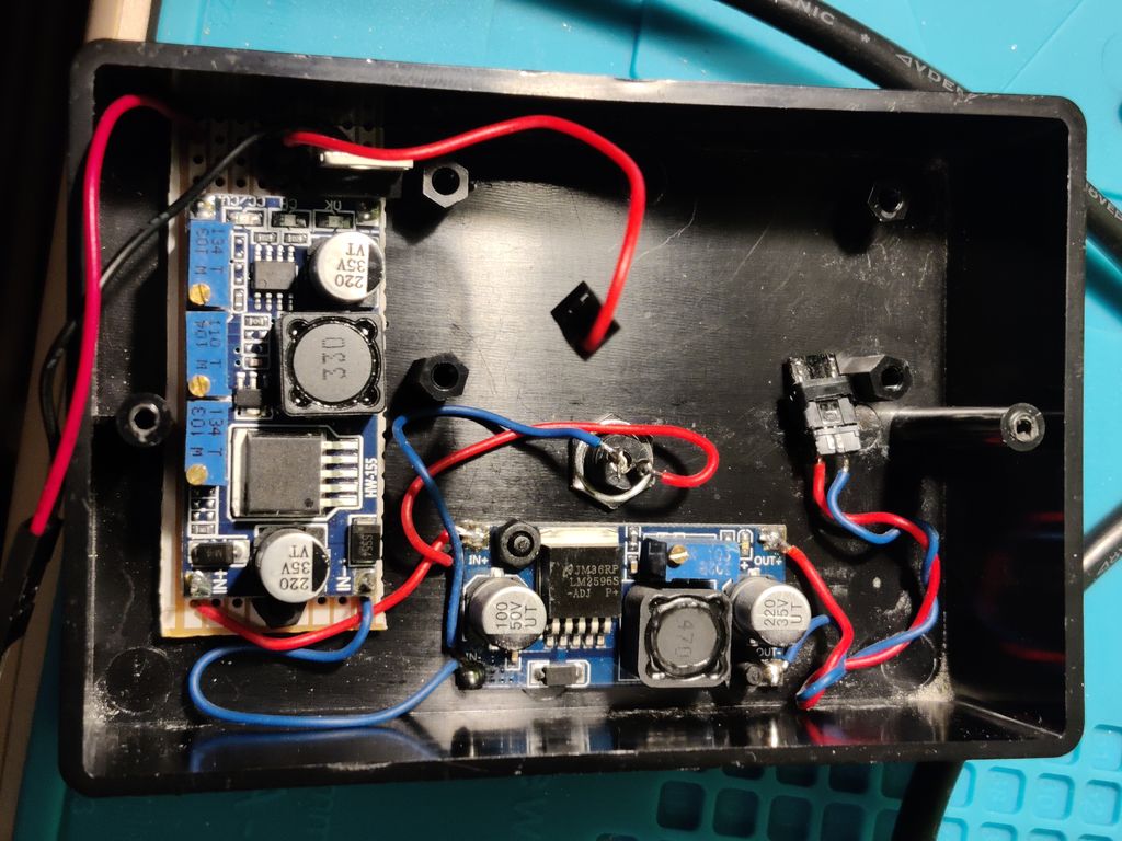
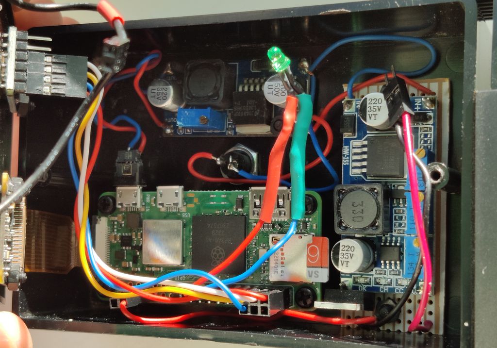
Job done, we can now hook everything together with solder and connectors (DuPont recommended).
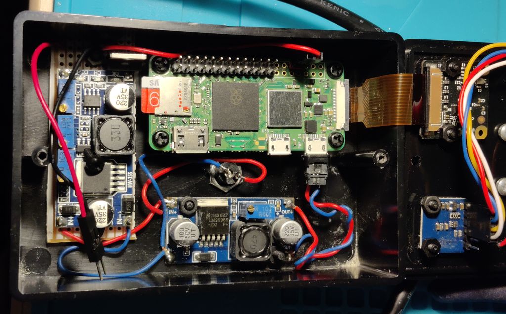
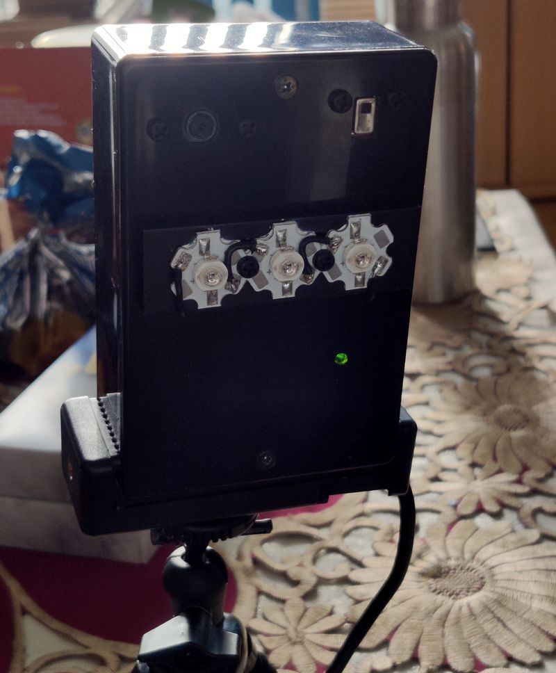
The image shows the wiring completion. The Raspberry Pi itself is mounted on nylon standoffs, otherwise the camera cable doesn't reach. The 6-pin DuPont header is for the AMG8833 (using 3.3V). The 2-pin header with only one cable is to the gate of the IRLZ34N, used to PWM the IR lights. The green LED is an off-board activity LED, configured using /boot/config.txt. This is so I can tell if the device is powered (and also whether busy). There's also unconnected 2-pin male and female DuPont connections to the IR LEDs.
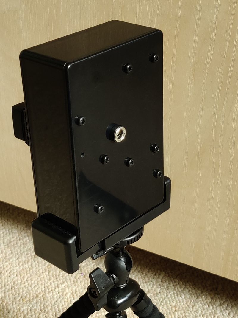
On the back is a single 2.1mm DC connector for the 12V power supply (centre pin positive).
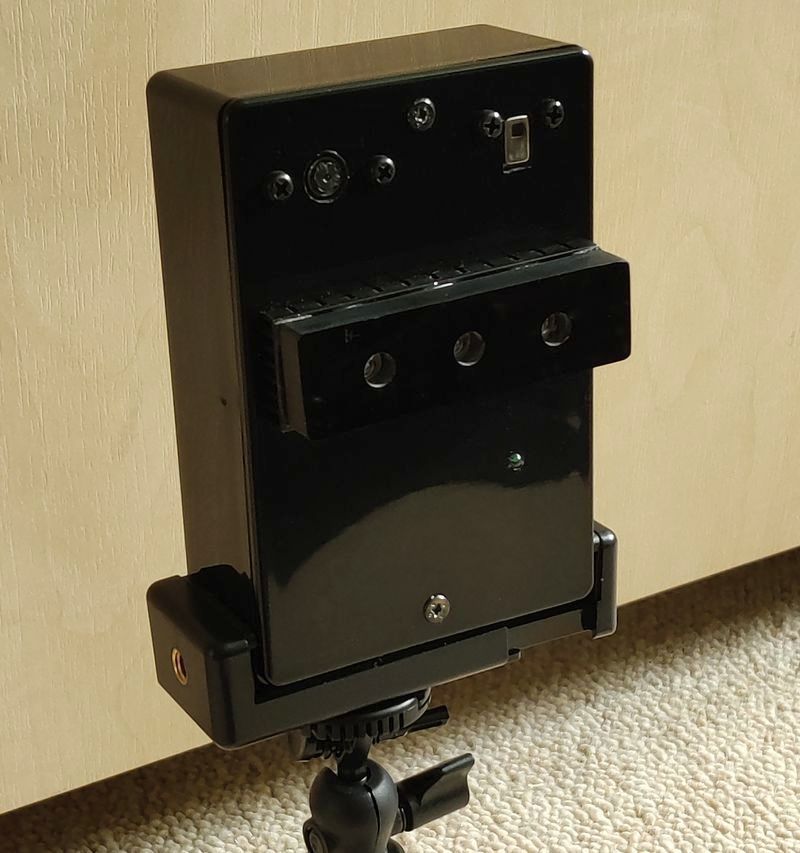
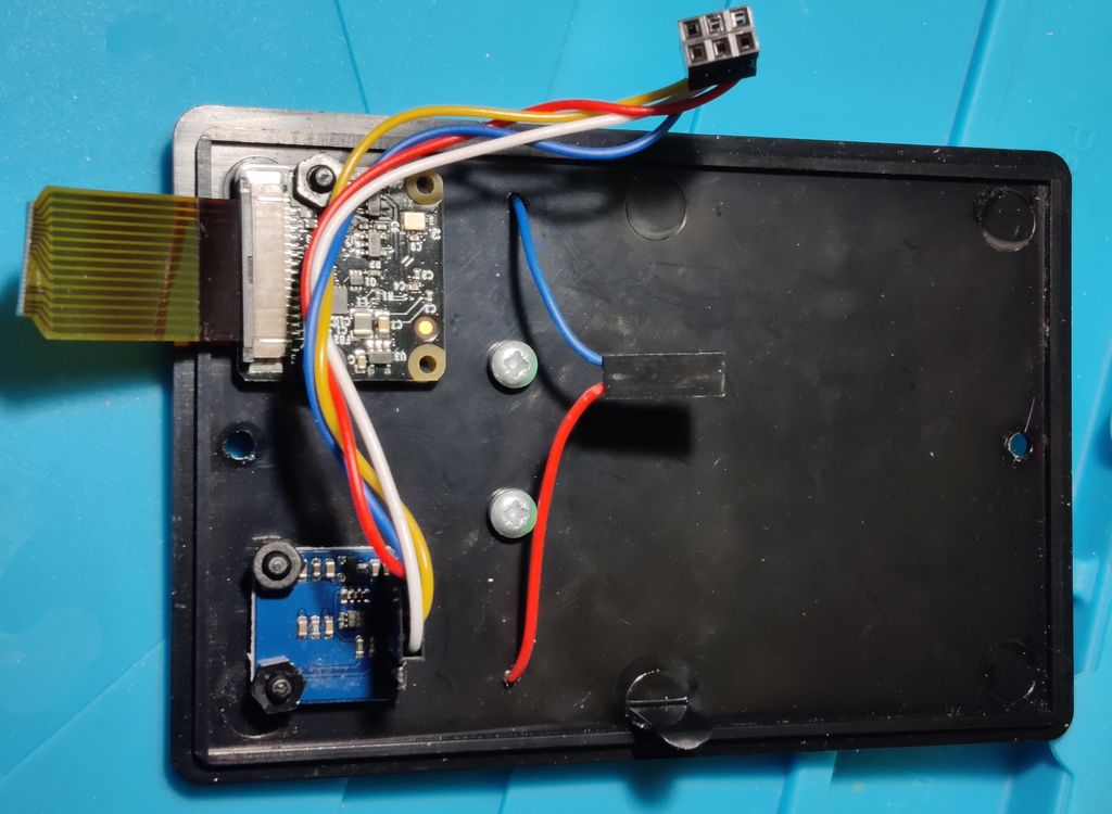
The LEDs are mounted on a NVMe heatsink which gives enough heat removal at the brightness I use them on. The fins are not exposed enough though, so I wouldn't recommend this for full brightness. Here's a picture of the camera in-situ with the LEDs visible:
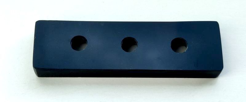
One of the challenges of the design is the IR LEDs are mounted in front of the camera. Generally, your light source should be behind the camera so a better design would have been to mount the No-IR Camera forwards and the LEDs further back. My solution was to mount a block of plastic over the LEDs to direct their light forwards only. The block was excavated for the LEDs using the drill bits and a Dremel rotary tool.
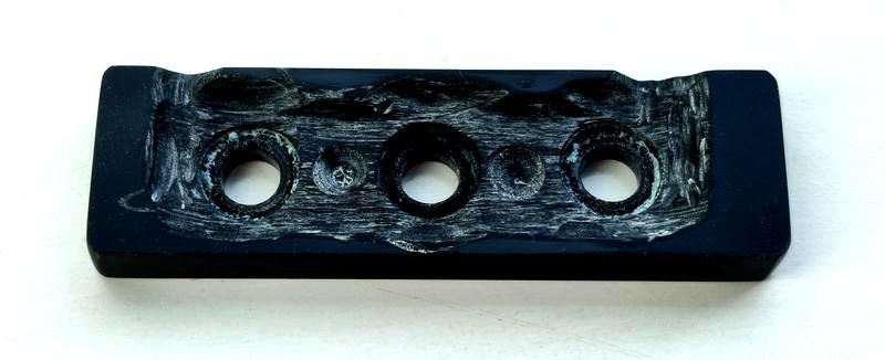
It did not work well though, as it turns out the thick black Perspex I used lets quite a bit of light through. I had to use aluminium tape inside the holes to resolve that.
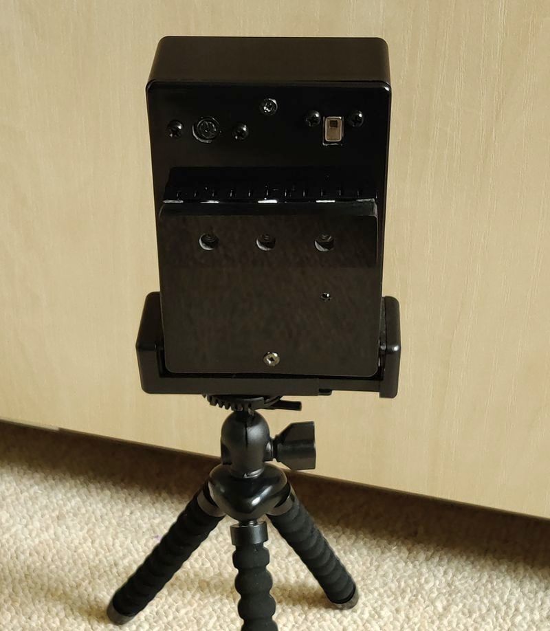
A phone tripod is used to hold the camera box and aim it where required.
Software
▷ My files file downloading / clone are available at github.com.
Operating System (OS)
![]()
For the OS, I'm using the standard Raspberry Pi OS Lite 32-bit bullseye version. That's because the UI is web based, meaning no GUI is needed for the OS. Please see my Raspberry Pi OS Tweaks page for installation recommendation and tweaks.
After installing and updating, some initial configuration adjustments are required. We'll need to enable I2C, PWM and the IMX219 overlay options.
I've also set up the external activity LED on GPIO22, and disabled audio since I have no speaker. If you need to play audio, bear in mind that the Pi Zero has no analogue output and since the PWM pins will be used for controlling the IR LED brightness, your only options would be a USB sound card or PCM/I2S module, or perhaps cheaper is a dedicated PWM module that connects via I2C or SPI.
sudo nano /boot/config.txt
Add, change or uncomment the following options:
...
# Uncomment some or all of these to enable the optional hardware interfaces
dtparam=i2c_arm=on
...
# Enable audio (loads snd_bcm2835)
dtparam=audio=off
...
# enable V2 camera (IMX219)
dtoverlay=imx219

# IR lights support (PWM)
dtoverlay=pwm,pin=12,func=4

# External Activity LED
dtparam=act_led_gpio=22
To enable the i2c driver, we also need put i2c-dev into /etc/modules. To do this quickly, run:
sudo sh -c "echo i2c-dev >> /etc/modules"
Alternatively, I2C can be enabled by running raspi-config.
We'll install git cmake gcc and g++ for building the projects we'll use:
sudo apt install -y git cmake gcc g++
camera-streamer
My requirement was to stream the cameras in an easy way to be consumed by a web browser.
Previously I used v4l2rtspserver which exposes a rtsp stream. That's good, but it's not that convenient as you need to open it in a media app on your phone or PC (such as VLC, although this wasn't always reliable), plus there was considerable delay.
Investigating again, I came across mjpg-streamer, which is pretty promising, but I found it tricky to get working with the camera (now that the supported camera interface is legacy). I would however still use mjpg-streamer for streaming images of the thermal camera (see below).
The camera-streamer project is used to stream the Pi's No-IR camera. This is more feature rich and can expose an MJPEG stream, but also H264 stream in mp4, mkv or m3u8 formats, and webrtc.
Both solutions use the JPEG encoder built into the Raspberry Pi, so are very efficient and consume 10% cpu or less even on the weak CPU of the Pi Zero 2.
This can be downloaded and configured by using the instructions on github.com here. What worked for me is the below. This will install about 260MB of additional packages:
PACKAGE=camera-streamer-$(test -e /etc/default/raspberrypi-kernel && echo raspi || echo generic)_0.2.8.$(. /etc/os-release; echo $VERSION_CODENAME)_$(dpkg --print-architecture).deb
wget "https://github.com/ayufan/camera-streamer/releases/download/v0.2.8/$PACKAGE"
sudo apt install "$PWD/$PACKAGE"
This streamer uses libcamera, which is now the recommended way to use Raspberry Pi camera modules. It provides hardware accelerated MJPEG and H.264 (AVC). MJPEG is ideal for embedding into web pages and H.264 is ideal for recording. This is all I need. I didn't experiment with ustreamer but this could be another great alternative.
It took me some time to get the streamer up and running. A challenge you might see is an error like this - note, logs can be checked by using "journalctl -xe" or "sudo systemctl status camera-streamer".
Jan 07 12:18:55 picam kernel: cma: cma_alloc: linux,cma: alloc failed, req-size: 2484 pages, ret: -12
Jan 07 12:18:55 picam kernel: unicam 3f801000.csi: dma alloc of size 10174464 failed
Jan 07 12:18:55 picam camera-streamer[1380]: [0:04:04.747627787] [1392] ERROR V4L2 v4l2_videodevice.cpp:1241 /dev/video0[24:cap]: Unable to request 4 buffers:
Cannot allocate memory
Jan 07 12:18:55 picam camera-streamer[1380]: [0:04:04.747756327] [1392] ERROR RPI pipeline_base.cpp:681 Failed to allocate buffers
This can happen if you try and stream max resolution or have specified an invalid resolution. Check supported resolutions by entering:
libcamera-still --list-cameras
Available cameras
-----------------
0 : imx219 [3280x2464] (/base/soc/i2c0mux/i2c@1/imx219@10)
    Modes: 'SBGGR10_CSI2P' : 640x480 [30.00 fps - (0, 0)/0x0 crop]
                             1640x1232 [30.00 fps - (0, 0)/0x0 crop]
                             1920x1080 [30.00 fps - (0, 0)/0x0 crop]
                             3280x2464 [30.00 fps - (0, 0)/0x0 crop]
           'SBGGR8' : 640x480 [30.00 fps - (0, 0)/0x0 crop]
                      1640x1232 [30.00 fps - (0, 0)/0x0 crop]
                      1920x1080 [30.00 fps - (0, 0)/0x0 crop]
                      3280x2464 [30.00 fps - (0, 0)/0x0 crop]
My service configuration is available here. Note that because I installed my camera upside down, both horizontal and vertical flip options are specified.
I've also specified the tuning file for the IMX219 NoIR camera, which improves the colour. The systemd service sets the environment variable LIBCAMERA_RPI_TUNING_FILE with /usr/share/libcamera/ipa/rpi/vc4/imx219_noir.json during the camera-streamer service start. I found out about the tuning file at the forum thread here. I'm not sure how I found out about LIBCAMERA_RPI_TUNING_FILE - some deep searching, I think!
To install this service, initially put it in your Pi's home directory, then copy it to the systemd directory:
sudo cp ~/services/system/camera-streamer.service /etc/systemd/system/
sudo systemctl daemon-reload
sudo systemctl enable camera-streamer.service
sudo systemctl start camera-streamer.service
sudo systemctl status camera-streamer.service
You should be able to see the index page from a web browser by going to the IP address or hostname of your Pi on port 8080. E.g. http://x.x.x.x:8080/
Thermal Camera Python Interpolate and mjpeg-streamer
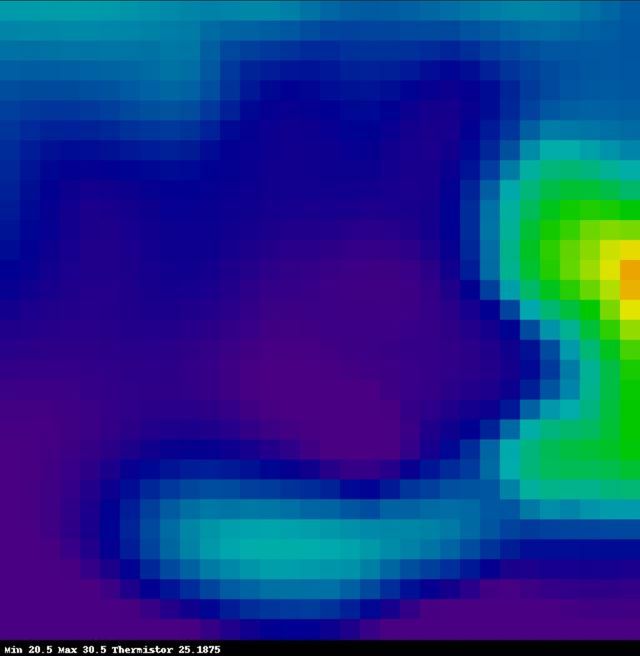
The thermal camera AMG8833, being the cheapest thermal camera out there, is popular enough to have existing code available for it. The native output of the sensor native form is poor - 64 pixels (8x8). It looks a little better interpolated, so a Python script can read the sensor, interpolate to a larger output which is steamed as JPEG. Since this Python script is resource intensive, I have made it on-demand and the Web Framework is able to start and stop it.
I tried libraries from both Maker Portal and Adafruit. I ended up mixing both of them in my own Python script, which uses the information to draw a JPEG image using the Pillows library. The 8x8 pixels are cubic interpolated to 64x64 (1024 pixels), and printed as 20x20 size pixels, making an image size of 640x640. This is updated as fast as possible into the /run/shm file system (in RAM).
The Python script does tax the CPU quite hard, but it updates quicker and uses less resources than the Maker Portal version. Still, it would have been nicer to code something in C++ or Rust, but these are languages I'm not that familiar with and they take much more effort than Python. To ensure more availability for the other services and connecting by web or ssh, I configured the Python script in its own systemd service and set a cap on CPU usage.
This is then streamed using mjpeg-streamer so it easily updates in a webpage. Whilst mjpeg-streamer for the Pi Camera I found tricky, it's ideal for streaming a file system updated image (sitting in /run/shm).
To setup the Python script, first we'll need some dependencies:
sudo apt install -y python3-pip python3-bottle python3-plac python3-scipy python3-smbus python3-matplotlib python3-dbus python3-colour
sudo pip3 install rpi-hardware-pwm
You can then copy the directory AMG8833_IR_cam into your Pi's home directory.
To set up mjpeg-streamer:
sudo apt install -y libjpeg-dev
git clone https://github.com/jacksonliam/mjpg-streamer
cd mjpg-streamer/mjpg-streamer-experimental/
make
sudo make install
You can use my thermal-camera-streamer.service as well as amg8833.service to set up the services for the thermal camera. Note that my thermal-camera-streamer service starts the interface on port 8081, and I've only enabled this service to start by default (amg8833 will start manually).
sudo cp ~/services/system/amg8833.service /etc/systemd/system/
sudo cp ~/services/system/thermal-camera-streamer.service /etc/systemd/system/
sudo systemctl daemon-reload
sudo systemctl enable thermal-camera-streamer.service
sudo systemctl start amg8833.service
sudo systemctl status amg8833.service
sudo systemctl start thermal-camera-streamer.service
sudo systemctl status thermal-camera-streamer.service
If you have trouble with the amg8833 service, you can also try and run the Python script directory using: python3 /home/picam/AMG8833_IR_cam/IR_cam_interp_stream.py
All being well, you should be able to access by going to port 8081 at your Pi's IP or hostname. E.g., http://x.x.x.x:8081/stream.html
Web Interface (Python Bottle)
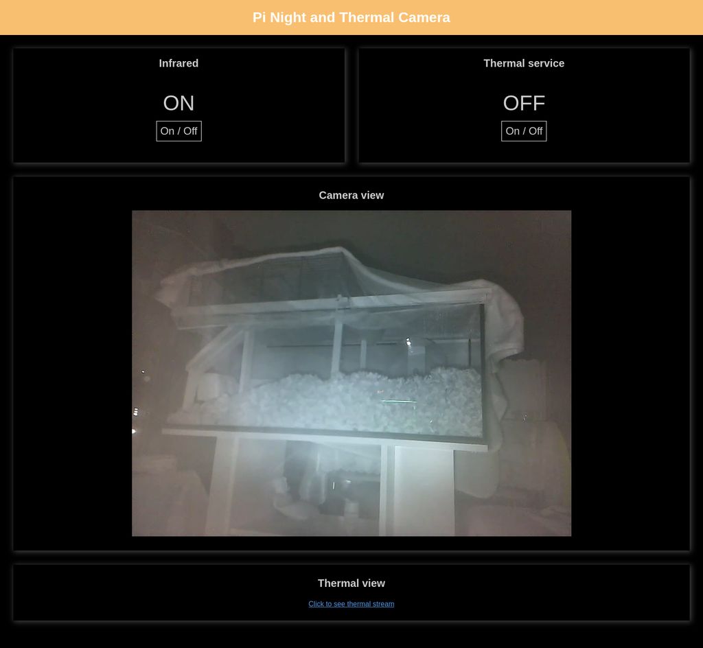
Bringing the two camera and control all together is a Python Bottle Web Framework script which exposes a simple web server that can handle callbacks. I wrote this myself, with some research, and it can control the on/off status of the IR LEDs, and the thermal camera service (turn on/off, as it is CPU consuming). I also added a shutdown feature (not directly linked from the home page).
Again, I went with Python here. The Bottle Web Framework is ideal for a simple service such as this as I can have all the code simply in one file and host a lightweight web service.
It works well, and my simple Python script (cameractrl.py) combined with HTML, CSS (cameractrl.css) and JavaScript (cameractrl.js) allows a simple web page with asynchronous callbacks (AJAX but using JSON instead of XML) to perform actions.
Actions include:
- status - returns the IR LED state and Thermal interpolating Service (amg8833.service) state.
- ir - toggles or changes the IR LED state if the "enabled" key is sent along with true/false.
- thermal - toggles or changes the Thermal interpolating Service state if the "enabled" key is sent along with true/false.
- shutdown - triggers a shutdown command after 1 minute. This allows me to remotely power off the Pi safely without ssh.
Having the actions tagged to the /action route allows JSON to be sent (as a POST) to the Raspberry Pi both from the JavaScript in its own control page (embedded in cameractrl.html) or another PC via CURL.
Enabling action requests like this allows me to schedule a service on my server (also running Linux, but Ubuntu Server edition) that can use CURL to turn on the IR LEDs, then use FFMPEG to record the camera stream to file, and CURL to turn off the IR LEDs once done.
To set up, copy my files cameractrl.html, cameractrl.css, cameractrl.js, cameractrl.py and shutdown.html into your Pi's home directory.
sudo apt install -y python3-bottle
You can use my bottleweb.service to set up the web service for the camera.
sudo cp ~/services/system/bottleweb.service /etc/systemd/system/
sudo systemctl daemon-reload
sudo systemctl enable bottleweb.service
sudo systemctl start bottleweb.service
sudo systemctl status bottleweb.service
The interface should be on port 8082 (try http://x.x.x.x:8082) - but the streams will not work until nginx has been set up...
Reverse Proxy (nginx)
I now have three web services using non-standard ports though:
- The camera-streamer runs on port 8080 (default)
- The mjpeg-streamer service runs on port 8081 (as configured in thermal-camera-streamer.service)
- The Python Bottle web framework runs on port 8082 (last line of cameractrl.py)
I wanted to bring everything together on port 80, so the whole system can be accessed just by navigating to http://hostname or http://ip address, and from the day job I know about reverse proxies already - however Apache / Oracle HTTP Server are way too fat for the job needed here!
There's nginx and lighttpd web servers available, but the former has a bit more info and support for reverse proxies. I've included in my GIT repo a modified default configuration for nginx that will proxy requests to /camera to port 8080, /thermal to port 8081 and anything else to port 8082 where the Bottle web framework is running.
To set up nginx:
sudo apt install -y nginx
The nginx default configuration is in the file /etc/nginx/sites-available/default. Edit that using:
sudo nano /etc/nginx/sites-available/default
Below is an extract of the added configuration lines (including the commented out original location):
location /camera/ {
    rewrite ^/camera/?(.*)$ /$1 break;
    proxy_set_header X-Real-IP $remote_addr;
    proxy_set_header X-Forwarded-For $proxy_add_x_forwarded_for;
    proxy_set_header Host $host;
    proxy_set_header X-NginX-Proxy true;
    proxy_pass http://127.0.0.1:8080;
}

location /thermal/ {
    rewrite ^/thermal/?(.*)$ /$1 break;
    proxy_set_header X-Real-IP $remote_addr;
    proxy_set_header X-Forwarded-For $proxy_add_x_forwarded_for;
    proxy_set_header Host $host;
    proxy_set_header X-NginX-Proxy true;
    proxy_pass http://127.0.0.1:8081;
}

location / {
    proxy_set_header X-Real-IP $remote_addr;
    proxy_set_header X-Forwarded-For $proxy_add_x_forwarded_for;
    proxy_set_header Host $host;
    proxy_set_header X-NginX-Proxy true;
    proxy_pass http://127.0.0.1:8082/;
    proxy_redirect http://127.0.0.1:8082/ https://$server_name/;
}

#location / {
    # First attempt to serve request as file, then
    # as directory, then fall back to displaying a 404.
    #	try_files $uri $uri/ =404;
#}
Recording
There are two types of recording you might want to do. One is locally, recording to the SD card. The other is recording on another PC instead (which has a big hard drive or SSD). Both can be done with FFMPEG.
My sample command is below for Linux (so will work locally, or on some Linux desktop/server). It splits recordings into 30 minute chunks as individual files (like dash cams do).
It's designed to start when you execute the script and continue until a defined time - in this case 10 hours after the start time (see runtime variable).
I use it for night recording, so before it starts recording, curl is used to POST the required JSON to the Bottle Web Service which will turn on the IR LEDs. They get turned off once the desired end time is reached.
#!/bin/bash
CAMHOST=picam.myhome.local
OUTDIR=/data/Videos/picam

if ping -c 1 ${CAMHOST} &> /dev/null
then
    curl --header "Content-Type: application/json" --request POST --data '{"action":"ir","enabled":"true"}' http://${CAMHOST}/action
    runtime="10 hour"
    endtime=$(date -ud "$runtime" +%s)
    while [[ $(date -u +%s) -le $endtime ]]
    do
        now=`date +"%Y-%m-%d-%H%M"`
        ffmpeg -i "http://${CAMHOST}/camera/video.mp4" -t 00:30:00 -codec copy -an ${OUTDIR}/picamstream.mp4
        mv ${OUTDIR}/picamstream.mp4 ${OUTDIR}/${now}.mp4
    done
    curl --header "Content-Type: application/json" --request POST --data '{"action":"ir","enabled":"false"}' http://${CAMHOST}/action
fi
Replace x.x.x.x with the IP address or hostname of your Pi camera, or localhost if running the recording script on the Pi itself.
The ffmpeg command simply copies to file the already encoded H264 (AVC) stream to disk to minimise CPU usage. If you wish to overlay timestamps or text, you'll need to re-encode.
If you are recording locally, I suggest getting a high endurance SD card which is better designed to handle constant writing - cheaper SD cards will wear out!
You can schedule this to start at a certain time of the day by creating a cronjob in cron. This is done crontab -e (there should be no need to have admin permissions to run the above script, so no don't run sudo crontab -e -as this will open a different instance):
This should open up nano editor on the pi, or maybe vi or per your preference. Then you can add your script with the minute and hour start time. This example starts at 9pm every day, of every week, of every month (so daily).
00 21 * * * /home/dan/Videos/picam/record.sh >> /home/dan/Videos/picam/record.log 2>&1
It'll create a log file in the same location as the script for diagnosis. This will contain output and errors (stderr redirected to stdout by 2>&1)
With the ffmpeg script and cron, I get 10 hours of overnight recordings starting from 9PM and running to 7AM in the morning daily.
Further tweaks
I've written a page of Raspberry Pi OS Tweaks that you should consider for this camera project. Most of those tweaks have been applied to this project.
If you apply my recommendations, for the stop/start of the amg8833.service to work, the /etc/sudoers.d/010_pi-nopasswd should look like below:
picam ALL=(ALL) PASSWD: ALL
picam ALL=(ALL) NOPASSWD: /usr/bin/systemctl * amg8833.service
picam ALL=(ALL) NOPASSWD: /sbin/shutdown
picam ALL=(ALL) NOPASSWD: /sbin/reboot
Conclusion
The updates to this project were done just in time (and a bit during) an introduction of a new gerbil to an existing one who was alone. This allowed us to record and monitor their interactions overnight whilst in the split cage and once together in a new big aquarium we got them. It also allows us to see them when we're out via my VPN.
So, this is a nice little project that will at least have occasional use. The Raspberry Pi and accessories are a great way that isn't too expensive to build your own projects. Perhaps buying a night camera and thermal camera separately may ultimately cost less, but I'd say this project was around £70 to £80 over time. Most of that cost is the cameras, and I'm excluding the cost of the ditched screen idea and a 12V PSU I already had.
In terms of hours of work - I've not spent that much. A few evenings here and there and it's up and running, although there was considerable time spent on research and improving the writeup and build. Some hours during weekends for the hardware build.
After learning and writing some code, I reinstalled and configured the whole camera within a couple of hours. Of course, buying is easier and quicker, but for me, doing things is a learning experience though and I enjoy the satisfaction at the end of having made something myself!
References and more reading:
- Raspberry Pi Camera Module V2
- Never Stop Building - Micro USB pinout
- Jeff Geerling - Fixing Blurry Focus
- Envistia - LM2596 how to use as LED Constant Current Driver
- Maker Portal - Thermal Camera Analysis with Raspberry Pi (AMG8833)
- Github.com makerportal AMG8833_IR_cam
- Github.com Adafruit - Adafruit_CircuitPython_AMG88xx/examples/amg88xx_rpi_thermal_cam.py
- Adafriut - Raspberry Pi Thermal Camera
- Github.com jacksonliam mjpg-streamer
- miguelgrinberg.com - Stream Video from the Raspberry Pi Camera to Web Browsers, Even on iOS and Android
- Stackoverflow.com - Create set of random JPGs
- Github.com dotnet iot - Enabling Hardware PWM on Raspberry Pi
- Python Package Index (pypi) - rpi hardware pwm
- Medium.com - Control your Raspberry Pi FAN using hardware PWM
- Electronut - Talking to a Raspberry Pi from your Phone using Bottle (Python)
- Fun Tech Projects - Pi Rover using a Bottle Web Framework
- Sudomod.com forum - External activity led on Rpi Zero
- [Japanese] Smartphone-Zine Kitsune Rider - Raspberry Pi Status LED
- Stackoverflow.com - How can query string parameters be forwarded through a proxy_pass with nginx?
- Serverfault.com - Nginx: How do I forward an HTTP request to another port?