
TDA1514/TDA2040 Surround Sound Amplifier - Mark 3 - Surround Sound Amplifier 2020 Remake
1 - Ideas and Design, 2 - PCBs, 3 - Amps, PSU and Grounding, 4 - Digital Control and Software, 5 - Results and Pictures
Part 3 - Building, Amplifiers, Power Supplies and Grounding
On this page...
TDA1514A Amplifier
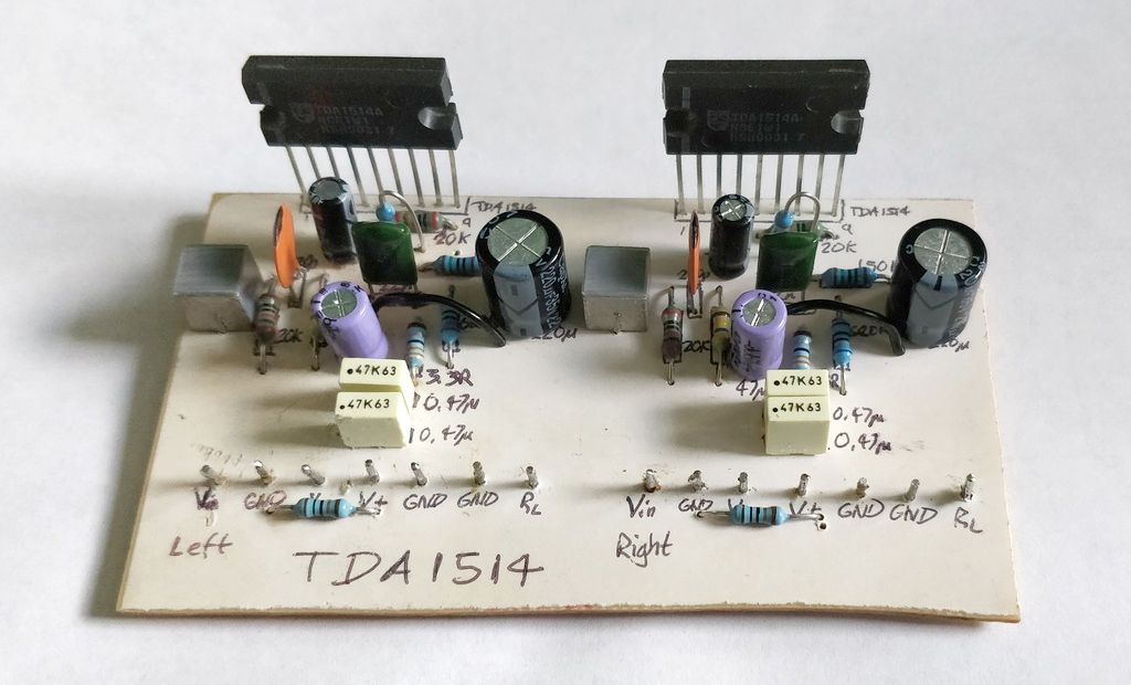
The star of the show is the TDA1514A amplifier. The board was made in 2003 and apart from some minor modifications I decided to keep it as it works well and any improvements would only be minor.
The changes I did make were to break the ground links on the board. There was one between each amplifier, so I broke that so the two amplifiers would only have their grounds joined at the star ground.
I also installed a hum breaking resistor between the signal ground and the power ground, however later upon testing found this did not work so the cut ground was joined again in the end.
I also changed the input capacitor from a 1uF electrolytic to a 2.2uF poly film capacitor. This should improve quality a little and bass response.
Finally, as my new speakers would be 4 ohm and the data sheet recommends that R4 is changed from 82 ohms to 47 ohms and R5 is changed from 150 ohms to 82 ohms, I did just that. I had no spare 82 ohm resistors so transplanted the original.
TDA2040 amplifiers
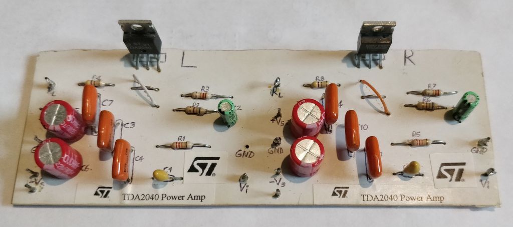
There were three of these. The original one was the 2x TDA2040 driving the rear speakers. Whilst I originally intended to reuse this board, it was very large, and I decided to build a new PCB which is shorter and could be located further away from the mains transformers to reduce hum.
Original:
New:
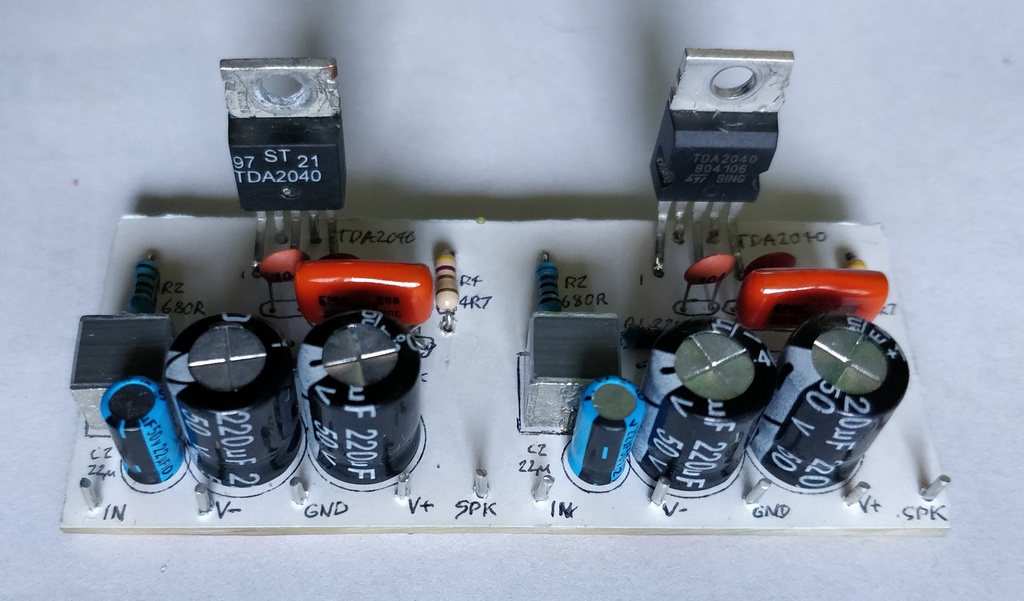
As can be seen, the new board layout is far more compact and all components were renewed since I had spares, except for the 4.7 ohm resistors which I had to de-solder and solder into the new board.
The input capacitors were changed to polyester film for the new board, and the values upgraded to 2.2uF.
The centre channel TDA2040 was removed. For years now I've never used the centre channel, and this allowed me to downsize the transformer a little to 60VA.
Power supply
The power supply would be altered, almost completely.
The 80VA 18V transformer used for the TDA1514 amplifiers would still be used, as would the bridge rectifier.
The 80VA 12V transformer used for the TDA2040 amplifiers would be replaced by a 60VA equivalent. This has a slightly smaller diameter which would allow both to be placed at one side of the case.
This was an important design change because the previous design had toroidal transformers at either side of the case, and therefore mains and AC secondaries crossing from one side of the case to the other - a design that would never lead to a quiet / hum free amplifier.
By locating both the transformers and their bridge rectifiers at one side of the case, where the mains connection enters, we're designating that area as the 'noisy' area and the sensitive electronics can be kept away from it.
An additional small 15VA 9V transformer was added for the digital electronics, and relays. This is always on because the PIC microprocessor is running constantly looking for an IR signal. It only consumes a few milliamps though.
The fuse for this small transformer is located on a PCB shown on the previous page. It's harder to access because it's unlikely to ever blow, and I don't have any more back panel room for another fuse holder anyway!
The existing two fuse folders looked a bit worse for wear after de-soldering, so I replace them with ones that fit the same diameter cut out. These now contain slow blow fuses for the 80VA and 60VA transformers, in line with the switched mains output from the board and the transformer itself.
This diagram shows one amplifier PSU. The second is just the same, but with the lower voltage transformer.
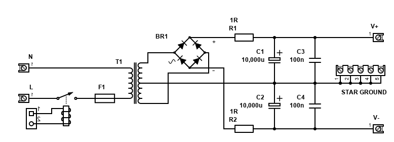
The mains power board replaces the old earth loop breaker, and also holds the mains switch relay, and a fuse for the small transformer. All connections to this board are screw down terminals to make a better (but removable) mains connection, except for the low voltage relay connection which is a 2 pin 2.54mm connector.
The bridge rectifiers for each of the amplifiers were reused but moved to a new location further from the amplifiers. The existing connections were de-soldered, and all wires renewed with 6.3mm spade crimp connectors instead. This makes a better connection, that's removable if needed.
Finally, another board was made for the DC smoothing capacitors. This is because they are the snap-in type and I wanted to use the 6.3mm spade connectors for the DC in and DC out connections on this board.
Grounding
Grounding was a tricky area on this amplifier, despite the re-work of the PSU and amplifier boards.
The principles I applied were the same as my main amplifier grounding, more specifically:
- A loop breaker so external loops caused by mains earth and interconnects are cut
- Safety earth connected to the chassis at one point
- Separate power and audio grounds (to the amplifiers)
- Star grounding - in this case two system stars because there are two separate power supplies
- No loops - as a starting point!
- Hum breaking resistor at the amplifiers - though this did not work
- Low resistance cable
- Twisted wires
I started off with the principles I successfully applied to my main HiFi amp - but the amplifiers were not happy with the hum breaking resistor, and once I removed that I had to do some experimentation to get the hum down to acceptable levels.
It's not perfect. I'd like to revisit it at some point, but the front amplifiers are almost quiet (hum only noticeable if you put your ear right up to the speaker), but the TDA2040 rear amplifiers are not as hum free and it is a little more noticeable, but you have to be fairly close and listen for it.
This is the layout I ended up with:
Most of it is normal star grounding, where there is a star at each PSU, and the preamp board. A separate digital ground star/bus too.
The unusual approach is the ground links between the preamp and each amplifier. Not only did I need a thick ground wire from each amplifier to the preamp board (despite there being a route to the preamp via the PSU stars), I also had to ground each end of the audio shield to minimise hum. Very unusual indeed because it's creating ground loops by offering the electrons more than one way to ground.
It is the best I could do though, and the hum is much better than the version 2 remake before. It highlights though the fact that having separate PSUs and separate amplifiers, with the preamp sharing one of them, all within the same system, complicates the grounding. A better design would have been to replace the TDA2040 with a chip that can handle +/-25V, such as the LM1875. A larger 120VA 18V transformer would then power all amplifiers fine with a single PSU, and a small separate 12V transformer could be used for the preamp.
I plan to revisit and take a fresh look at the grounding and wiring scheme of the amplifier at a later date (in particular I'd like to use twisted pairs for all input wires), so for now I recommend you don't apply the techniques I've used to make it work and instead start with the normal techniques and experiment from there only if they do not work.
Part 4 - Digital Control and Software...
References and more reading:
The Audio Pages - Elliott Sound Products