
TDA7391 / TDA7396 DIY Guide - 35W / 45W Mono Single Chip Power Amplifiers
The TDA7391, TDA7396 and TDA7391LV are all very capable amplifier chips of which all are still readily available as of August 2020. They allow you to easily build high performance mono amplifiers.
Recommended Experience : Beginner to Intermediate, knowledge of amplifiers, heatsink attaching
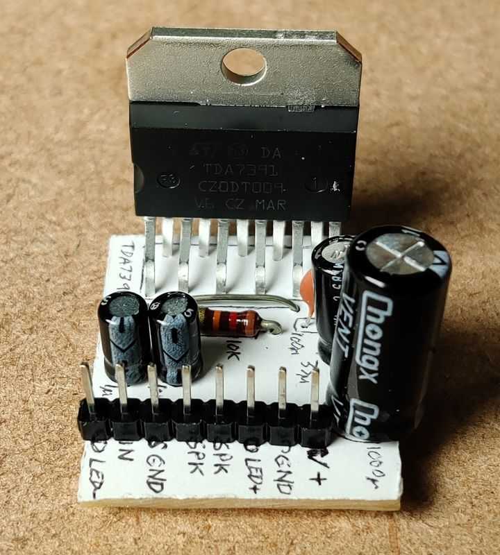
TDA7391 application
Quick facts TDA7391
- Power output: 32W into 3.2 ohms at 10% 1kHz distortion with power supply 14.4V
- Power output: 26W into 4 ohms at 10% 1kHz distortion with power supply 14.4V
- Power output: 24W into 3.2 ohms at 1% 1kHz distortion with power supply 14.4V
- Power output: 21W into 4 ohms at 1% 1kHz distortion with power supply 14.4V
- Power output: 26W into 4 ohms at 1% 1kHz distortion with power supply 16V
- Power output: 14W* into 8 ohms at 1% 1kHz distortion with power supply 16V
- Power output: 15W into 4 ohms at 1% 1kHz distortion with power supply 12V
- Power output: 8W* into 8 ohms at 1% 1kHz distortion with power supply 12V
- Gain: 26dB fixed
- Power supply: 8V to 18V single supply
- Class AB
- Datasheet available here
* these 8 ohm figures came from the TDA7391LV datasheet, which has the same performance into 4 ohms as the TDA7391
Guide
The TDA7391 is a simple to build amplifier that can deliver impressive power output into both 3.2 ohm and 4 ohm speakers from just a single rail power supply of 12V, and even more power when supplied with up to 18V.
The TDA7391 is clearly aimed at car audio with its ability to drive 3.2 ohm speakers, and no quoted information about power drive into 8 ohm speakers. 8 ohm speakers will of course work fine though, and you can expect a similar power output as the TDA7391LV. Some applications you could use this chip for are:
- Driving a small to medium sized ported subwoofer
- Bluetooth speaker
- ICE - in car entertainment subwoofer
- You can use pairs (or more) of them to expand the possible applications out further
The information here is based on the typical application circuits in the ST Microelectronics datasheet. The performance from this circuit is excellent. The sheet contains data for typical noise and distortion statistics and whilst I can't confirm these statistics, I can confirm it works brilliantly.
For lower power applications, you may want to consider the TDA7391LV chip instead, which can operate down to 6V. If you need to run on lower voltages, then the TDA7266M is a good option for down to 3V, or otherwise look to the low power chips like the TDA2822M / TDA2822D or LM386.
This chip can operate into 3.2 ohm speakers, bridged. It's a niche requirement to drive a 3.2 ohm speaker though (three 8 ohm speakers in parallel become 2.7 ohms which is too low for this amplifier), so typically you'll be interested in powering 4 or 8 ohm speakers instead.
It can drive 4 ohm speakers with ease and will of course work into 6 and 8 ohm or higher speakers fine too.
For those whose want a dual/stereo amplifier though, the alternatives are the STA540 / TDA7375 chips, or the TDA7297 / TDA7266 chips.
Circuit
The TDA7391 is for a bridged mono output only. There are minor differences in the circuit configuration to allow for a balanced differential input, or a normal single ended input.
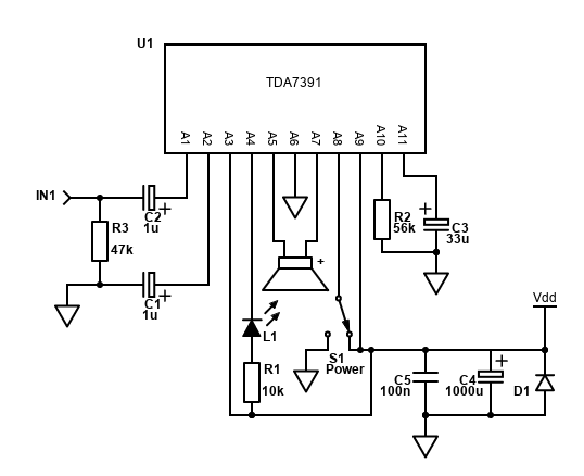
The circuit I'm showing and have tested is the single ended input configuration. This is the type of input we'll normally have which consists of a mono signal and a return on the ground path.
Because the amplifier is a single supply bridged amplifier, the speaker needs no DC blocking capacitor (this is because both outputs will be at ½ the voltage supply, so no DC current flows through the speaker). The components it does need (only 6 excluding diagnostics), are cheap and easily obtained.
The gain of the TDA7391 is fixed at about 26dB - that's a voltage gain of 20 times, calculated as 10^(dB/20), so 10^(26/20) = 20). This means, it's pretty sensitive and unlikely to need a preamp. It matches its stereo cousins too (e.g. TDA7375) allowing it to integrate into a multichannel system.
With a 12V input power, the TDA7391 can drive a 4 ohm speaker (which is 2 ohm bridged) to about 15W RMS at 1% distortion. To calculate the voltage of this, it's V = √(15 * 2) = 5.48V RMS. Divide that by 20 and it's a 274mV RMS input signal required to drive the TDA7391 to maximum power, with 1% distortion. I found the output from a smartphone or many other sources can easily drive it to clipping.
With a 16V PSU, 27W power output into 4 ohms is achievable at 1% distortion. That input signal to reach that power raises to 368mV, which is still an output most input sources can meet.
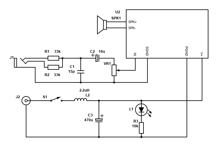
The above circuit shows the amplifier with a switch used for the power stand-by or fully operational. You'd need a SPDT switch to toggle between ground (for stand by) or Vdd (operational).
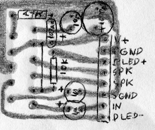
The TDA7391 is best with a custom PCB, and my PCB Building guide has information on how you can draw and etch a custom PCBs. The layout below shows how small it can be - at just 29mm x 27mm. Note that R3 is not included in this layout, but can be accommodated easily enough by mounting vertically at the IN and Ground terminals (as I did when I added it later).
Note that my PCB does not include the power switch. Pin 8 is connected directly to Vdd, therefore the amplifier is operational immediately after supply power. The muting circuit (C3/R2) keeps the amplifier muted momentarily until the power stabilising (preventing speaker 'pop' during power on).
The TDA7391 is a Multiwatt 11 package and unlike the Multiwatt 15 the pins are spaced further apart (at around 3.5mm). Therefore, it won't fit into stripboard / Veroboard. If you've no desire to build a PCB, you can buy an LM3886 adaptor/breakout board which will fit this chip, or you could wire point-to-point. I've tried neither myself.
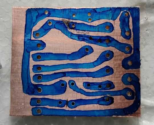
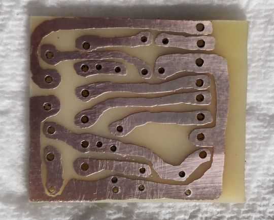
Above: TDA7391 PCB hand drawn etch resist on copper
Above: TDA7391 PCB post etching and clean
Components
| # | Type | Quantity |
|---|---|---|
| U1 | TDA7391, TDA7391LV, or TDA7396 | 1 |
| R1 | 10k ohm Resistor, ¼W Metal Film, 1% | 1 |
| R1 | 56k ohm Resistor, ¼W Metal Film, 1% | 1 |
| R3 | 47k ohm Resistor, ¼W Metal Film, 1% | 1 |
| C1,C2 | 1µF Capacitor, Polyester Film/Box (Best) or 16V+ Electrolytic | 2 |
| C3 | 33µF Capacitor, 16V+ Electrolytic | 1 |
| C4 | 1000µF Capacitor, 25V+ Electrolytic | 1 |
| C5 | 100nF Capacitor, 50V+ Ceramic X7R or MLCC | 1 |
| L1 | LED, high brightness | 1 |
| In,SGND,+Vs,GND,SPK,DIAG | 2.54mm header 8-pin | 1 |
| Heatsink, cable, connectors | ~ |
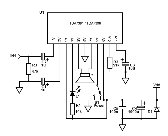
Like all amplifiers, the TDA7391 needs bypass capacitors C5 and C6. That's a 1000uF or better electrolytic capacitor, and a 100nF ceramic or multi-layer ceramic (MLCC) capacitor. Make sure the electrolytic is oriented correctly with + in the positive power supply.
Both C5 and C6 need to be as close to the amplifier pins as possible, with C5 (the 100nF ceramic) being the closest. As pin 3 and 9 are quite far apart, for the best power supply bypassing, you may prefer to add a second 100nF capacitor (same as C5) from pin 9 to ground as well as pin 3 to ground.
C4 needs to have a voltage rating of a few volts or more greater than the power supply you want to use. Therefore, a 16V capacitor is fine for a 12V PSU, but if you want to go higher with the voltage, get a 25V or 35V rated capacitor. The datasheet suggests 1,000uF for C4, but if you have a good power supply with capacitance exceeding this already, then C4 could be dropped to 470uF or 220uF.
As the TDA7391 is a single supply amplifier, it generates a virtual ground internally that is half the supply voltage. This allows the audio input signal to swing above and below this virtual ground. It's a rail-to-rail amplifier too, so at maximum power this means the TDA7391 can drive the speaker output all the way from 0V to its supply voltage. This is why it can output impressive power for an amp limited to the potential difference of its supply rails.
The input capacitors C1 and C2 protect that DC voltage offset from reaching your input source (or ground). These are 0.22uF (220nF) input capacitors in the datasheet, but you can raise these to 0.47uF or 1uF to get the best bass response. I used 1uF. Polyester is preferred for best audio quality, but an electrolytic works fine too and unless you're using this amp for the absolute best speakers in a quiet environment, you'll unlikely to notice the difference. The + pin of the electrolytic must be facing the amplifier pins.
The voltage the capacitor needs to handle is half the supply voltage plus the peak AC input (no more than 2V), a 16V rated capacitor is fine for C3 and C5, but 1uF electrolytic capacitors are usually 50V or 63V rated or higher anyway.
R3 was added to ensure the amplifier has a reasonable input impedance to sources. I found the TDA7391 was unstable when driving it from a mobile phone when testing until I added this resistor from the input to ground, therefore I also recommend you add this into your design too.
In the standalone applications (with no microprocessor), R1 is for the diagnostics LED, and R2 for the mute timing. Neither need to be high quality resistors as there is no audio in either. R3 is flowing audio to ground and also does not need to be high quality. High quality 1% metal film resistors are still cheap though so feel free to use them anyway.
C3 is a capacitor connected from the pin 11 ground. It's used to determine the time the amplifier stays muted after receiving power, allowing the amplifier to be powered on with no pops on the speakers. Get a capacitor rated to ½ the voltage supply, though it's unlikely you'll get a 10uF capacitor under 16V.
Do not run this amp without a good heatsink, it will get extremely hot very quickly and shut down. Get a good heatsink, and if pushing the voltage to its maximum or 3.2 ohm speaker, get a really good heatsink! The heatsink internally connects to ground which shouldn't cause a problem for most applications, however if your using the amplifier on mains power and your case is earthed (it must be for safety), you may need a loop breaker to avoid hum caused by other equipment that is also earthed, and in this case the TDA7391 would need to be isolated from its heatsink in order to avoid shorting the earthed case to the amplifier power and signal grounds.
When mounting the amplifier chip to the heatsink, also use a line of thermal paste, and let the pressure of screwing it onto the heatsink push out the paste to cover the entire back of the tab. It's important to use thermal paste to improve the heat transfer, but do not use too much.
Making a 'system'
If you want to build your own mono amplifier system, you'll need a little more than the circuit and components above.
- A power supply - see below, but suggest an external power supply
- A DC jack such as a standard 2.1mm jack. It should match the plug on the power supply
- A power switch, such as a slide switch, toggle switch or latching push button
- A power LED and current limiting resistor (you may have an LED in your power button you can use)
- 3.5mm jack input or phono sockets for connecting your source
- A potentiometer, 10k log is recommended
- Optional, but recommended, capacitor to block radio interference
- Optional, but recommended, a capacitor and inductor to improve PSU noise
- Optional, but recommended, capacitor in front of potentiometer to block DC
- If your speaker is separate from the amplifier, spring clips, female banana plug sockets or similar should be used to attach/detach the speaker
Since the fixed gain is reasonable, it's unlikely you'll need a preamplifier and you'll be able to use most sources directly. This could be your TV, smartphone, a Bluetooth audio module, Chromecast audio (if you can find it to buy) or many other devices.
The TDA7391 is a mono amplifier, so I've shown two resistors to sum the 3.5mm stereo connection to a mono signal. These are not needed if your source is mono anyway.
When connecting all connections, tightly twist the related wires together. This is applicable to all related connections where there is a signal and a return, so twist the input with the signal ground together, twist each speaker +/- wires together, and twist the voltage + supply and power ground together.
Twisting related flow/return wires together likes this both prevents them radiating interference, and also protects them from interference. Each twisted set in a system should be kept away from each other and if they must be close, let them cross at right angles and don't run them parallel to each other. This is to reduce hum.
The PCB layouts above have the signal and power grounds joined together at the board, therefore do not have these connecting anywhere else to avoid hum caused by ground loops. If you do have a wider system and have these power and signal grounds joined at another point, consider removing the join at the board and replacing it with a 10 ohm resistor, in parallel with a 100nF capacitor.
The potentiometer can be a single gang one, as we are only amplifying one channel. 10k Log type is ideal. It will have three pins - the first pin will be the one connected to signal ground, the middle pin to the audio input and the final pin as the audio output (going to the amp). This will ensure that turning the volume control clockwise raises the volume, anti-clockwise lowers it.
Before the volume control is a 10uF capacitor (C2). This blocks any DC offset the source may or may not have. DC voltages cause the potentiometer to become noisy over time (particularly when adjusted), so the capacitor in improves their life. We don't have to worry about any capacitor after the volume control because the capacitor is the first component in series with the input signal at the amplifier itself.
At the input is an RC low pass filter. The component values are not too critical here, it's just to ensure signals of MHz's are removed so with the combination of 33k ohms and 15pF (picofarads), frequencies above 320kHz are removed. This will remove any GSM pulsed buzz / interference from mobile phones, as well as any AM radio stations creeping in.
The two resistors R1 and R2 allow a stereo source to be summed to a mono signal, without causing any challenges for the source. If your source is mono already though, a single resistor is all that's needed. You can reduce it to 1k and increase C1 to 470pF for a slight reduction in noise.
At the power supply, the switch is first, on the positive line. I suggest to get a latching push button switch with an LED built in for convenience but check whether the LED needs a resistor or not (some are 12V ready). Otherwise having a separate LED to indicate whether the power is on is useful. The value R3 should be adjusted to suit your power supply and LED type (search for LED resistor calculator).
Then there is a filter formed by a 2.2uH power inductor (capable of handling 6A current) and a 470uF capacitor (this must be a low ESR type). These are there to reduce the ringing/whining noise from noisy SMPS power supplies. Anything above 5kHz on the PSU is cut. You may not need the inductor if your power supply is quiet, but I still suggest the capacitor for smoothing the voltage.
Power Supply
I recommend, especially for beginners, that an external power supply is used. This should be a linear power supply or switching power supply that is suitable for audio/video use (i.e. a 12V, 16V, 17V or 18V laptop power supply). These types of power supplies are easy to obtain.
Be wary of cheap power supplies ordered from the far east and elsewhere because although they may work fine, they won't be safe in overload or other situations (lightning strikes etc.). The CE symbol on these devices is either fake or means 'China Export' and isn't the European certification that guarantees the product conforms with health, safety, and environmental protection standards.
With a 12V supply, this amplifier can give 15W into 4 ohms. For many applications this will be enough, and for a single amp a 30W PSU is fine (2.5A for 12V).
16V power supplies for laptops can also be found. This will let the amplifier get 34W into 4 ohms. Now we need to look for an 60W supply minimum, that's 3.75A at 16V. A higher power will do no harm.
If you decide to build your own power supply, you can use a 12V AC 60VA transformer to get about 17V DC when rectified. See the TDA2003 article for a suitable schematic, but bear in mind you will be working with mains electricity. The unregulated output from this should be fine, but if you want the best noise performance, using regulator capable of 5A or more (LM338T for example) with large heatsinks.
Performance
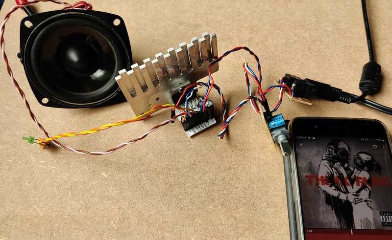
Above: First test of the TDA7391
Unsurprisingly, the TDA7391 delivers great audio. It sounds good and it's perfect for driving a small, medium or even larger speaker like a medium sized subwoofer. Off a low voltage power supply, these chips are unbeaten for their power output and the only way to get more power off a voltages available in a car for example would be to buck boost the voltage up to something higher and use more powerful amplifiers.
TDA7391LV
The TDA7391LV is an improved TDA7391 that will operate off 6V. It operates in the same circuit as the TDA7391, except the application circuit instead recommends 220k for R2 and 2.2uF for C3.
The Electrical characteristics curves seem to indicate that it even operates from 4V, but assuming you want to run it from 6V capable chip, you can only expect 4W into 4 ohm speakers, and 2.5W into 8 ohm speakers (at 1% distortion). Still, that's way better than an LM386!
TDA7396 application
Quick facts TDA7396
- Power output: 45W into 2 ohms at 10% 1kHz distortion with power supply 14.4V
- Power output: 27W into 4 ohms at 10% 1kHz distortion with power supply 14.4V
- Power output: 35W into 2 ohms at 1% 1kHz distortion with power supply 14.4V
- Power output: 22W into 4 ohms at 1% 1kHz distortion with power supply 14.4V
- Power output: 34W into 4 ohms at 1% 1kHz distortion with power supply 16V
- Power output: 15W into 4 ohms at 1% 1kHz distortion with power supply 12V
- Gain: 26dB fixed
- Power supply: 8V to 18V single supply
- Class AB
- Datasheet available here
The TDA7396 is an enhanced TDA7391 that can operate into 2 ohm speakers. Because it's a bridged amp - that's representing a 1 ohm load to each amp half, practically a short circuit! It's an impressive feat, but it's a niche requirement to drive a 2 ohm speaker unless you're building a car subwoofer, and if that's the case you'll probably need a more powerful amplifier with buck boost to reach higher voltages.
Still, it's an impressive feat, and it's not uncommon to drive car subwoofers into 10% distortion which will let this chip deliver 45W of power to a speaker operating in a small mostly enclosed space and that will be enough for all except the biggest show-offs!
The TDA7396 will drop right into the same circuit board as the TDA7391, but it has a different recommendation for R2 and C3, being 51k and 10uF, respectively.
Therefore, read the above guide for the TDA7391 since it is just as appropriate.
Because the TDA7396 has a greater power output potential with a 2 ohm speaker - do not skimp on the heatsink! If you're pushing it into such a challenging load at high volume, it will get very hot. I suggest keeping the supply voltage no higher than 16V constant for a 2 ohm speaker. With this, you'll get 42W of power at 1% THD (quite impressive!).
Microprocessor control
If you want to use a microprocessor to control the standby and mute of this amplifier - it's possible.
The datasheet tells you pin 8 is the standby pin, only mentioning that high makes the amplifier operational, and low (0V) puts it in standby mode. The pin is CMOS compatible meaning you can connect this pin directly to your microprocessor. The threshold for on is 3.5V though, which will be a problem for 3.3V logic microchips. A MOSFET can solve that though. Using a microchip to drive standby will also work for the TDA7391/TDA7391LV.
Muting is also possible by driving pin 11, the MUTE pin, with an NPN transistor. Figure 3 gives the circuit for both mute and standby application. Note that the TDA7396/TDA7391LV chips do not specify a mute microprocessor drive possibility in their datasheets, but it may work fine (the block diagram is the same).
The datasheet requests a ratio of 0.63 to 0.69 between REXT to RS (R3 and R2 above). If we keep RS as 47k, that gives a 30k resistor for REXT (ratio is 0.638 for this). A better ratio is possible using the 51k resistor RS suggested in figure 1. This allows a 33k resistor to be used (ratio is 0.647).
REXT to RS (R2 and R3 in my diagram) form a critical ratio, and these should be 1% tolerance resistors so that ratio between them is not broken.
With transistors used for both standby and mute, these signals can be driven by 3.3V or 5V microprocessors, therefore the microprocessor can be an Arduino, PIC or similar MCU, or it can be the GPIO pins of a Raspberry Pi or similar computer.
If your microprocessor is 5V, you could drive the standby pin directly, even with no resistors since the TDA7396 sinks only a small amount of current and is therefore CMOS compatible.
Driving the signal high takes the amplifier out of standby, and again driving the mute line high takes the amplifier out of mute. I suggest a timing suggestion of 100ms to 200ms between the amplifier exiting standby and the amplifier unmuted to avoid any popping noises.
The diagnostics pin can also be fed to the input pin of a microprocessor too, allowing power to be cut in fault conditions, or muting on clipping (just ideas for programming). This will need a pull up resistor to the microprocessors power supply.
For convenience, I've shown all three connections (pin 8 for standby, pin 11 for mute and pin 4 for diagnostics) in the schematic below, but removed the rest of the pin connections for clarity.
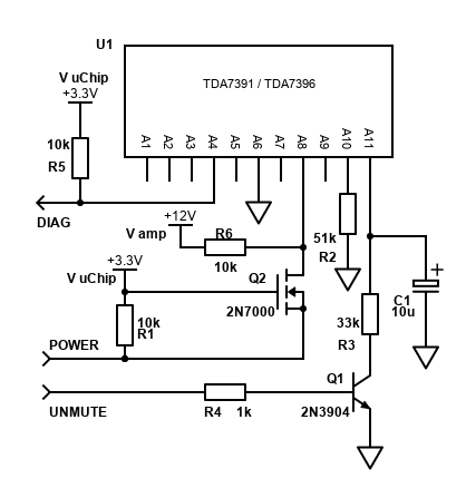
Note: I've not built and tested any of these chips on a microprocessor, therefore the above schematic is not verified, but should be fine. Contact me if you've verified it yourself.
No power output into 8 ohms is quoted by the datasheet, but it will drive 8 ohms fine and expect it to have pretty much the same power output into 8 ohms as the TDA7391LV.