
LM1875 / TDA2050 / TDA2040 / TDA2030 / TDA2006 DIY Guide - 12W to 32W Single Chip Power Amplifiers
This article now combines information for all these chips - you may been redirected here from the TDA2030 or TDA2040 article.
Warning: The TDA2006, TDA2030, TDA2030A, TDA2040 and TDA2050 chips by ST have all been discontinued and are mostly fakes now. If you're buying them, make sure they are from a good supplier to get the genuine chip otherwise performance will be bad, the chip may be easily damaged and create a hazard, or hum/buzz may be worse than the official chip.
The TDA2050 is the slightly superior chip to both the TDA2040 and LM1875 in that it can deliver more current (and therefore power) into speakers before shutting down, but it is widely faked. There's absolutely no way that the TDA2050 chips on AliExpress, eBay etc. can deliver the power output when they are sold as cheap as 10 pence each! Some sellers might be selling the genuine chip (or a desoldered used one) for a higher price, or they'll be taking some big markup or unaware even that they are selling fakes because some 3rd party middle-man sold them to them. It's a risk you take!
These days, there are also many kits available online. You get the PCB, IC and all components in one order which is cost effective but the IC used in these is also likely to be of dubious quality, as well as the capacitors. The PCBs look ok though.
UTC (Unisonic Technologies) make clones of TDA2030, TDA2030A, TDA2050 and LM1875 too. I've not tried any, but they are more recent and some have reported these are ok.
There are also other Chinese clones such as D2050 (not 2SD2050!), UTC2030 by Youwang Electronics, YD2030 by WuXi YouDa Electronics, CD2050CZ by Wuxi China Resources Huajing Microelectronics, TDA2030 and TDA2050 by Tiger Electronic Co. which are all similar to ST's originals. Quality of these are unknown and I've not tried them.
The best choice is the LM1875 chip by Texas Instruments as still more readily available. They are in stock at reputable UK suppliers for example. The circuits shown below are just as appropriate for that chip too (the pins are the same).
Also available is the LM675. This is marketed more as a power operational amplifier which is equally capable with DC applications as well as AC, instead of marketed as high performance audio, but THD performance is the same as LM1875. I've never tested it myself and recommend the LM1875 for audio (it should be cheaper anyway), but if you can only get the LM675 chip, it should also work fine in the circuit featured below as an audio amplifier.
Recommended Experience : intermediate, knowledge of amplifiers, split rail power supplies, PCB etching, heatsink attaching, and mains qualification
Comparison
All of these chips are 5 pin Pentawatt (TO220 similar) devices that basically operate in the same circuit, with minor differences in component values.
Quick facts
- Class AB
- Low harmonic distortion
- Short circuit protection
- Frequency Response 20Hz to 100kHz (recommended circuit is 20Hz to 20kHz)
- Gain: 30dB using datasheet components (adjustable 24 to 33 dB)
Performance difference
The table below is a comparison of key performance differences. Note that the voltage range is from absolute minimum to the absolute maximum limits - for reliability, you should aim to use a voltage supply that is 2V under that limit.
There's quite a range of different chips, but generally the cheapest ones are listed first (at least when they were actively produced and sold). The choice if you're building new is pretty much LM1875 from TI (Texas Instruments) now, but the datasheet doesn't give the information to compare it to the various TDA single chip amplifiers from ST (SGS Thompson).
| Package | Voltage supply range | Power at 10% 1kHz THD - 8 ohms | Power at 10% 1kHz THD - 4 ohms | Power at 0.5% 1kHz THD - 8 ohms | Power at 0.5% 1kHz THD - 4 ohms | Power at 0.5% 1kHz THD +/-14V - 8 ohms | Peak current limit |
|---|---|---|---|---|---|---|---|
| TDA2006 | +/-6V to +/-15V (+12V to +30V) |
8W from +/-12V | 12W from +/-12V | 6W from +/-12V | 9W from +/-12V | 11.8W | 3A |
| TDA2030 / UTC2030 | +/-6V to +/-18V (+12V to +34V) |
11W from +/-14V | 18W from +/-14V | 9W from +/-14V | 14W from +/-14V | 9W | 3.5A |
| TDA2030A | +/-6V to +/-22V (+12V to +44V) |
- | - | 12W from +/-16V (40Hz-15kHz) | 18W from +/-16V (40Hz-15kHz) | 9W (40Hz-15kHz) | 3.5A |
| TDA2040 | +/-2.5V to +/-20V (+5V to +40V) |
16W from +/-16V | 29W from +/-16V | 12W from +/-16V | 22W from +/-16V | 9.2W | 4A |
| TDA2050 | +/-4.5V to +/-25V (+9V to +50V) |
22W from +/-18V | 35W from +/-18V | 18W from +/-18V | 28W from +/-18V | 12W | 5A |
| LM1875 | +/-8V to +/-30V (+16V to +60V) |
- | 25W from +/-25V (1% THD) | - | 8.8W | 4A |
Note that TDA2030A power is measured and quoted in the datasheet only in the range of 40Hz to 15kHz, so it looks worse and is not comparable to the other chips that were measured at only 1kHz. Also the performance of the LM1875 is only measured at 1% THD.
The second to last column is an interpretation from the datasheet graphs using the same PSU rails of +/-14V and speaker load of 8 ohms for all chips. What's interesting here (if the data is correct!) is the TDA2006 chip is able to give more power for the same voltage, suggesting that if your voltage supply is lower than +/-14V (or 28V), this is the better pick. The TDA2030A is also a newer alternative (but still discontinued) to the TDA2030 that has performance comparable to the TDA2040, except still the lower peak current.
Datasheets
- TDA2006 Datasheet
- TDA2030 Datasheet
- TDA2030A Datasheet
- TDA2040 Datasheet
- TDA2050 Datasheet
- UTC TDA2050 Datasheet
- LM1875 Datasheet
Guide
These simple single chip power amplifiers are very popular, having started in the mid 1990s to early 2000's. Their applications are similar, but here are some ideas:
- A pair can form a capable amp for a stereo system (i.e., a homemade or upgraded midi system).
- This amplifier can be used to complete surround sound systems (i.e., centre and rear channel amps). I use the TDA2040 amp for my rear and centre channels in my original surround sound system.
- A pair can be used to improve the sound from a TV.
- Beefing up those 400W+ amps in PC speakers (seriously)!
- Tweeter or mid-range amplifiers in bi-amp or tri-amp systems, thanks to their low distortion.
- Bluetooth speaker
- Active Hi-Fi speaker systems with an active crossover (TDA2040 and TDA2030A datasheets even show examples)

This amplifier is based on the typical applications in the ST Microelectronics datasheets for the TDA2030, TDA2040 etc. The performance from this circuit is very satisfactory. The sheet contains data for typical noise and distortion statistics, and they're good. My non-scientific listening test for the TDA2040 and TDA2030 amplifiers that I have built meets expectations too!
The circuit above is suitable for all chips, however you may want to leave out some components. You can try to make this amps on a Veroboard / Stripboard PCB, but you will have a risky job to mount the IC onto the board, as well as risk of creating an amp that oscillates due to board layout constraints.
A custom PCB is much better, and that's how I've built all my amps. You can layout the tracks in the way you prefer, drill the holes, etch it then solder in the small number of components with minimal effort. The ST Microelectronics datasheets (linked above) contain suggested PCB layouts, which I've used, or you can design your own and make it more compact for today's component sizes (I've done both methods).
See my PCB Building Guide for a novice guide to drawing and etching your own PCBs using only cheap equipment.
Note: The above image is copied directly from the datasheet and is not mine, nor is it likely to be 1:1 scale. To achieve this scale, the best idea is to print to PDF file to A4 paper.
The datasheet PCB layout is the same for all the TDA chips and includes space where stability and protection components may be installed. Whilst the TDA2040 (and TDA2050) datasheets make no mentioned of needing the extra components, it you have a problem with stability you can install (for example) a 2k resistor and 330pF capacitor in series between pin 2 and 4.
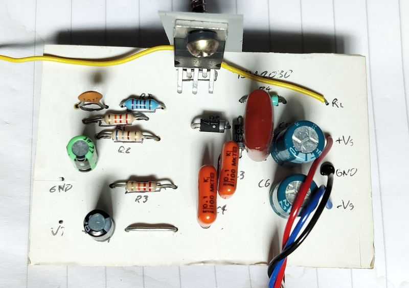
Below is a picture of my old TDA2030 amplifier PCB using the above layout:
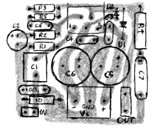
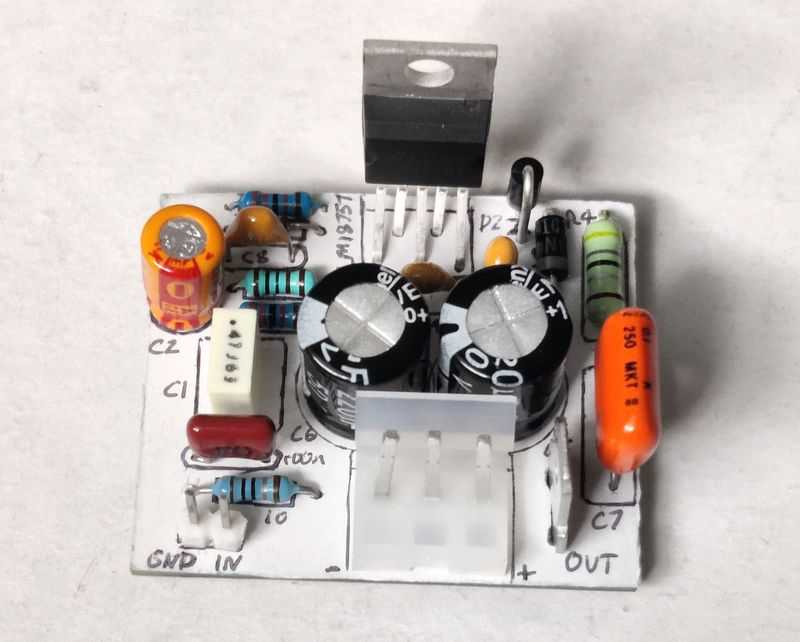
An alternative layout is below, which measures 4.8 x 3.5cm. This is hand drawn and scanned at 300dpi and should print to the correct size if you wish to use it. I use this layout as a UTC-TDA2050 tweeter and mid amplifier for my work stereo / radio system, and it performs well.

This layout includes a little room for protection diodes. A hum breaking resistor and capacitor is also included to lift the input ground from the power ground. This is optionally and may help with a multi-channel or bi/tri-amplifier systems where the main audio grounds are located elsewhere. It is not required for a mono amplifier though.
Room for stability gain components is also included and those gain components are located top left near the chip for best performance. Input capacitor C1 should fit a standard polyester box (film) capacitor up to 1.5µF (note, my build uses a 470nF capacitor because it's a tweeter amp and does not need the bass extension). Zobel capacitor C7 fits an orange-drop polyester capacitor.
The connectors required are a 2-pin PCB header, standard 2.54mm spacing for the input (bottom left). Dupont connectors can fit these. The power supply connection uses a 3-pin wire to board 3.96mm spaced header (CH W2B Molex). The speaker output uses a PCB mounted 6.3mm Quick-Connect (often known as spade) disconnect. The speaker ground is not included as it should go to your star ground at the PSU for most systems.
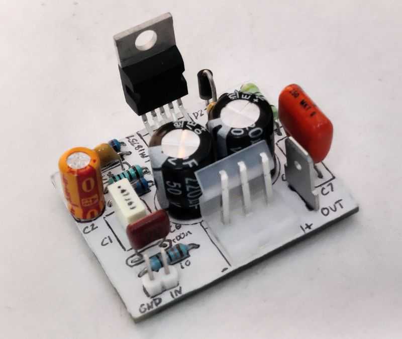
Below is an earlier revision which also works well and is slightly smaller at 4.6 x 3.9cm, and pictured below.
Components
| # | Type | Quantity |
|---|---|---|
| U1 | LM1875, LM675, TDA2006, TDA2030, TDA2030A, TDA2040, or TDA2050 | 1 |
| R1,R3 | 22k ohm Resistor, ¼W Metal Film, 1% | 2 |
| R2,R7 | 680 ohm Resistor, ¼W Metal Film, 1% | 1 |
| R4 | 4.7 ohm Resistor, 1W Carbon, 5% | 1 |
| R5 | 2k ohm Resistor, ¼W Metal Film, 1% | 1 |
| C1 | 2µ2F Capacitor, Polyester Film/Box (Best) or 16V+ Electrolytic | 1 |
| C2 | 22µF Capacitor, 35V+ Electrolytic | 1 |
| C3,C4 | 100nF Capacitor, 50V+ Ceramic X7R or MLCC | 2 |
| C5,C6 | 220µF Capacitor, 35V+ Electrolytic | 2 |
| C7 | 100nF Capacitor, 50V+ Polyester Film/Foil/Orange Drop (Best) or Ceramic X7R | 1 |
| C8 | 47pF Capacitor, 50V+ Ceramic X7R | 1 |
| C9 | 1nF Capacitor, 50V+ Ceramic X7R | 1 |
| D1,D2 | 1N400x (i.e. 1N4001, 1N4004 etc.) | 2 |
| Vin | 2.54mm header 2-pin | 1 |
| +Vs,-Vs,GND | 3.96mm CH W2B Molex 5239/KK396 3-pin | 1 |
| Vout/Spk | 6.3mm Quick-Connect (Spade) PCB Disconnect | 1 |
| Heatsink, cable, connectors | ~ |
All resistors are recommended to be ¼W 1% metal film. The Zobel resistor (R4) needs to be a minimum 0.5W resistor for lower power builds, ideally 1W+.
Capacitors should be electrolytic with values greater than 1µF. For the 2.2µF input capacitor (C1), polyester may be preferred instead for best sound quality, but an electrolytic also works. Bypass capacitors (C3, C4) should be Ceramic or Multi-Layer Ceramic (MLCC). Zobel capacitor (C7) is best as polyester, but Ceramic should be fine too.
Ensure that electrolytic capacitors are connected the right way round - pay attention to C6 as the positive terminal is in ground, not -V supply.
Ceramic Bypass capacitors (C3, C4) should be close to the IC pins.
ST recommends protection diodes D1 and D2 for the TDA2006 and TDA2030 amplifiers to protect against output voltage spikes, but the TDA2040 and TDA2050 amplifiers make no mention of them, except their PCB layouts do include spaces for them. My TDA2040 amplifiers do not contain them and survived years, but given their cost for 1N400x diodes, and PCB space they'd need, I'd suggest including them anyway as they'll do no harm.
If you do add the diodes, make sure you solder them the right way round, otherwise they'll destroy your amplifier instead of protecting it (and maybe your PSU too)!
The TDA2006 and TDA2030 datasheets also include upper frequency cutoff components, shown as R5 and C8 in the above schematic. Again, they're not mandatory and my TDA2040 amplifiers have not included them, but if stability is a concern, then the values of R5 and C8 can be worked out from the equations in the datasheet.
- R5 should be approximately 3 × R2. If R2 is 680 ohm then R5 should be 2.04k. Round to the nearest value, which is 2k, or I used 1.8k in my TDA2030 build.
- C8 should be approximately 1 / (2 × π × B × R3) where B is the -3dB cutoff in Hz. So that we don't lose too much detail from 10kHz to 20kHz, I suggest to pick a cut off of 150kHz for the frequency (B in the equation), then: 1 / (2 × 3.14159 × 150000 × 22000) gives 4.82E-11. Pico-farads (nF) start at 10-12, so this is 48.2pF (pick 47pF). With 47pF under simulation, I find the response is only 0.2dB down at 20kHz at the output. The -3dB point is more like 80kHz.
I've added R7 and R9 too as an additional ultrasound filter. This arrangement is common on many chip amp designs and discrete designs and further attenuates high frequencies. With R2 as 680 and C9 as 1n, the 20kHz point is still only 0.25dB down, the -3dB point at the output is 70kHz and above 100kHz is a steeper rolloff.
With C1 as 2.2µF, the response is just 1dB down at 20Hz. Increase C1 further if you really need to go lower. Below is a simulation plot with recommended values:

Also added, but not mandatory, is R9. This resistor gives a path for DC to discharge from C1 or any capacitor on the output of a preamp (for example), without affecting the input impedance too much.
Do not run this amp without a good heatsink, it will get very hot very quickly and likely die. Get a good heatsink, especially at high voltages into 4 ohms. It must also be insulated from the metal tab on the back on the chip, because this tab is connected to the -V supply, not ground. This usually means mica washers, or Kapton tape. Avoid Sil-Pads unless running at low voltages where heat generated from the chip is low. Only if you are operating at low voltages can you get away with a small (medium-sized) isolated heatsink per chip.
If you're choosing the TDA2050 or LM1875 and a higher power supply voltage, the heatsink should be even larger due to the greater power dissipation. I'd say at least 10x10x3cm for a single amplifier, though the bigger, the better!
The gain using the components per datasheet is 30dB. That's a good value and how most of my amplifiers have all been configured. If you wish to change this though, the values of R2 and R3 determine this where the voltage gain is 1 + (R3/R2) e.g., for R2 of 680 ohm and R3 of 22k ohm: 1 + (22000/680) = 33.35. In dB this is 20 × log(33.35) (assuming an input voltage of 1V RMS), which equals 30.46dB. If adjusting the gain, do not go below 24dB as it will become unstable.
A gain of 27dB was used in my LM1875 implementation that runs the tweeter in my tri-amped centre channel. For this gain, use 1k for R2 and 22k for R3. R5 would be 3k.
R5 and C8 stablises the amplifier because at frequencies above the cutoff, the capacitor passes these currents instead of blocking them, and the amplifier uses a lower gain of 1+(R5/R2) at these frequencies. With R5 as 2k and R2 as 680 ohm, this is a gain of 3.94 (or 12dB).
Capacitor C2 is used to reference the inverting input to ground. As shown, this is a 22µF capacitor, but you may increase it to 47µF for further bass extension. With R2 as 680 ohms, and C2 as 22µF, the -3dB cut off is 10.6Hz. That's almost an octave below 20Hz, so should be fine - it'll be about 1dB down around 21Hz. Using 47µF gets you to just under 5Hz. The calculation for the -3dB cut off is 1/(2πRC).
If you're using the LM1875 in active bi-amp or tri-amp system as a mid or tweeter amp, you can lower the value of C2. This gets you into the range of cheaper polyester capacitors, and these are known to have better sound quality. For a mid-range amplifier, consider a cut-off two octaves below your lower crossover point, i.e., 75Hz for a midrange operating above 300Hz. A 3.3µF (only 0.23dB down at 300Hz) or 4.7µF (0.12dB down) would work well. Polyester capacitors will have a fair cost at this size, but they become affordable and not huge in size (there is no need to get large speaker capacitors for this purpose - they'll compromise the board layout).
For tweeters, assuming a low crossover point of 1.4kHz, you can get away with a 1µF capacitor (0.12dB down at 1.4kHz). You can also lower the size of C1 to 100nF.
Component variations
While the above schematic should work fine for all amplifier chips listed, the datasheets do have some variances:
For LM1875:
- Zobel network: R4 (R5 in LM1875 datasheet): changed from 4.7 ohms to 1 ohm.
- Zobel network: C7 (C5 in LM1875 datasheet): changed from 0.1µF (100nF) to 0.22µF (220nF).
- Feedback loop: R2 (R3 in LM1875 datasheet): changed from 680 to 1k
- Feedback loop: R3 (R4 in LM1875 datasheet): changed from 22k to 20k
This configuration gives a gain of 21x / 26.5dB. You can happily keep R3(R4) as 22k though for a slightly higher gain of 23x / 27.2dB, this is what my build uses, along with 4.7 ohms and 100nF for the Zobel network.
For TDA2006 and TDA2030:
- Zobel network: R4: changed from 4.7 ohms to 1 ohm.
- Zobel network: C7: changed from 0.1µF (100nF) to 0.22µF (220nF).
For TDA2050:
- Zobel network: R4: changed from 4.7 ohms to 2.2 ohms.
- Zobel network: C7: changed from 0.1µF (100nF) to 0.47µF (470nF).
Components for the Zobel network are just for stability and the values used in the TDA2040 schematic will still work fine in the other chips.
As noted, for the LM1875, the feedback loop values change the gain to 27dB instead of 30dB.
I've not tested every combination, but in general all of these chips will be compatible in each other's circuits so long as you're within the voltage supply limits for the chip, so pick component values for the gain you need, or go with my standard values above.
Performance
After wired correctly, these chips make great amplifiers. All could be considered Hi-Fi, thanks to their low distortion, but the power output will limit their ability to drive Hi-Fi speakers to their limits (especially true for TDA2006). It will compete against older midi and mini systems though, and lower powered amplifier chips.
Power and distortion statistics are all listed in the datasheet and above. My recommendation (for all these chips) is to match them to speakers of 8 or 6 ohm minimum. Though 4 ohm loads are possible, they are pushing the current capabilities of the chips.
I use two TDA2040 these amps in my surround sound system - for each rear channel. I also have a TDA2030 stereo amplifier which originally was my bedroom / office Hi-Fi amplifier (now replaced by an LM3886 amplifier though). The sound from these systems is very good, capable for movies and music.
These amps will also suit many other purposes, I will leave you to use your imagination, but I do recommend them for their simplicity, cost and performance. The TDA2050 offers the most power, but the LM1875 is nearly as capable. I have not built either yet myself though, but many others have success with the LM1875, and an article is on the ESP Audio Pages here.
If you are looking at driving 4 ohm speakers and need more power, the TDA2030A offers a 'high-power' design using BD907 and BD908 'booster' transistors to handle most of the load instead. This will work for all the chips featured here, but you now have three devices to mount on a heatsink and it'll become a costly design.
With booster transistors, it can push 35W into 4 ohms off a 39V (or +/-19.5V) PSU. BD907/BD908 will be hard to get, but similar transistors can be used instead such as TIP41B/TIP42B, TIP41C/TIP42C, TIP31B/TIP32B, TIP31C/TIP32C, TIP2955/TIP3055 (larger) - they all have the same pin order (B, C, E). All devices will need to be isolated from the heatsink using mica washers or kapton tape so they don't short to the heatsink.
Layout will be crucial. I'd also recommend reading ESP IC Power Amplifiers - How To Get More Power for more ideas and knowledge of limitations. A thing to note is distortion will be worse with booster transistors. This will be harder to notice with lower frequencies so it's recommended only as subwoofer / low frequency woofer amplifier.
Power Supply
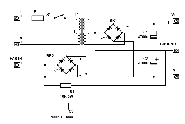
A power supply for this amp can be a simple split rail linear power supply. The maximum voltages per chip vary and are listed above, e.g., for the TDA2040, +/-20V is the absolute maximum, so aim for +/-18V as a sensible maximum. Wiring up a 12-0-12 transformer will give +/-17V and is recommended. This means mains wiring so:
THE POWER SUPPLY REQUIRES MAINS VOLTAGE WIRING. DO NOT WIRE IT UNLESS YOU ARE SUITABLE QUALIFIED, DEATH OR SERIOUS INJURY MAY RESULT.
Your transformer size will depend on your amplifier, output voltage, and the number of amplifiers in your system.
For one amp, 40VA transformer should be sufficient in most cases, meaning if you have two amps, 80VA is the recommended minimum. For the TDA2006 amplifier, given the power output and voltage is quite low - you'll need 9V AC (9-0-9) to get +/-13V, a 30VA transformer will be enough.
The maximum supply voltage of +/-25V for TDA2050 and LM1875 can be obtained by a 18V AC transformer (18-0-18). As the power is higher too, I would recommend a minimum of 60VA for one amp. Double this for two (120VA).
A capacitance of 4,700µF is a typical ideal for the PSU capacitors. You can also go for 10,000µF or use 2x 4,700µF per rail for the best transient bass performance. 2,200µF would be consider the minimum you can get away with, though mid/tweeter amps could use less still (there are forums where people have found the amp brighter with less).
The capacitors should have a voltage rating of 35V minimum. You can only go for smaller voltage ratings if the unloaded voltage is comfortably below the capacitor's max voltage (for example 25V capacitors will be OK for a +/-17V TDA2040, 18V OK for +/-13V TDA2006).
A fuse should be installed, I will leave it to you to work out what's appropriate because of the world-wide mains variations. Also be sure to correctly earth the supply and any metal casing around it.
The components on the earth and ground connections form a loop breaker. This is recommended construction because it can eliminate an earth loop. R1 is a 5W or better wire-wound resistor. The 100nF capacitor must be a Class-X rated for 250V AC, you cannot use a 250V DC cap as it would fail open and burn if there ever was a fault causing mains to flow to earth. Check your country's rules and regulations before constructing this as it may be illegal. If so, omit all these components and connect the earth directly to ground but never disconnect the earth lead... it could save your life or somebody else's!
Bridge Version
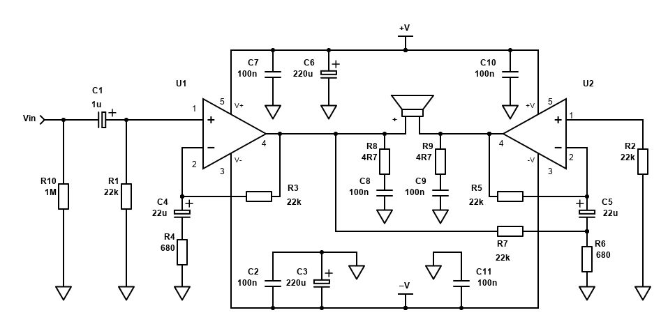
The datasheets also contain circuits for bridged circuits. Bridge circuits allow up to four times* as much power into the same impedance with the same voltage supply. In the example of a TDA2030A amplifier into 8 ohms with +/-16V, the power goes up from 12W to 34W.
*As can be seen, the power output is also not four times greater. This is because the current capability of these chips is not sufficient enough - they would be physically larger if so. Their intended use is in to 8 ohm speakers instead of 4 ohms and because bridging the amplifier will make each amplifier 'see' a 4 ohm load, limits apply.
I have not yet tested a bridge version yet, but if you got a need for it and understand the limitations then it could be worth building. The cost will be higher, but it will still be cheap for a reasonably powerful amp.
The limitation of this approach is that complexity and distortion will be a bit worse. This is because output distortion is fed from the output of the first amplifier to the inverting input of the second. Still, it is good enough for many uses, especially lower frequency drivers (i.e., subwoofers) where the distortion will not be noticed. An alternative to bridge with a little lower distortion would be to use two amplifiers and add a op-amp based bridging adaptor (see ESP Project 14). Bear in mind though that there are many ICs that are already bridged and will be simpler (e.g., the STA540), as well as modern class D amplifiers being a very good alternative for subwoofers especially.
When wiring the loudspeaker, never short it to ground, and do not use the bridge circuits on 4 ohm speakers (8 ohm is now the minimum load).
The power supply for the bridge version is the same as above but double the transformer VA rating. For example, if a single TDA2040 needs 40VA, this means 80VA for mono bridge version, or 160VA for stereo bridge (4 chips in total). Because each chip is pushing an effective 4 ohm load, the power supply rail should not exceed +/-18V for LM1875 and TDA2050. Up to +/-22V is possible, but it is really pushing the limit of power dissipation.
Single Supply
If you have a single supply system, the ST datasheets all give single supply alternatives. These are pretty much as per the split supply versions, but a virtual ground is made from a voltage divider (R1 and R2) to create a ½ VS DC voltage (smoothed by C2) that is applied to the non-inverting input (pin 1).

This ½ DC voltage will appear on the output too though, so needs to be removed by the large DC blocking capacitor C6 on the output pin 4.
Therefore, the cost is extra resistors and capacitors, including that large 2,200µF capacitor in series with the speaker which will be quite expensive in cost and room that is consumes on the PCB. Making it smaller will affect bass response - 1000µF will get down to 20Hz for 8 ohms, 40Hz for 4 ohms. The calculation for the cutoff is 1/(2πRC) - e.g., for 8 ohms, 1000µF it's: 1/(2 × 3.14159 × 8 × 0.001) = 20Hz.
Do note that the single supply version will also have quite loud power on and off thumps through the speaker. This will be due to the capacitors charging and discharging during the power cycle. The best way to solve this is an external muting circuit.
The single voltage power supply possible varies per chip, e.g., for the TDA2040 it can be up to +36V with a current rating of 1.2A for one amplifier. Double the current rating for two, quadruple it for stereo bridge! If you are buying an external PSU, make sure it is good quality and ideally for audio/video, otherwise noise/whine may come through. If you can't get a PSU with the current rating, go higher as there's no harm.
I recommend you purchase a good quality (has audio as a stated purpose) SMPS (switching power supply) for the single supply version of the amp. This will give good performance and avoid the need for transformer and mains wiring.
However, if you have a transformer available that only has one secondary and isn't centre tapped, then you could use that to build a single supply linear PSU:
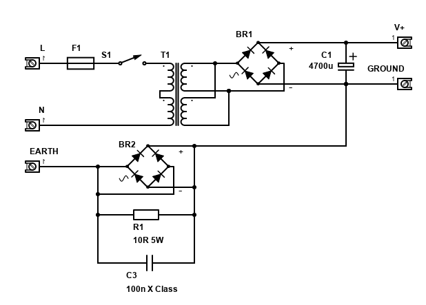
The VA rating will need to be the same as the split rail PSU - e.g. for a TDA2030 then a 40VA transformer with a secondary voltage of 24V AC will give around 34V DC.
No datasheet suggests a single supply bridge circuit, but it would be possible by replicating the voltage divider (R1, R2, C2, R3) to drive the non-inverting input of the second amplifier directly. The large output capacitor (C6) would also need to be replicated for the second amplifier on the other side of the speaker, or the capacitor can be left out completely from both amplifiers if they both have a very closely matched DC offset from the voltage dividers. If you do that, you'll save cost and room, but it should be for an integrated system as any short of the two terminals to each other or ground from speaker leads will cause serious issues!
It's hard to recommend a BTL single supply version, especially when there are amplifiers nowadays (like STA540) that would do the job cheaper and safer.
If you have the chips available though, and are looking to build a low power, but great sounding, Hi-Fi amplifier, all these chips would be suitable and are very popular. The performance of the single ended (not bridged) amplifier is very good and despite the design is over 20 years old, but the LM1875 is still available today.