
TDA7052 / TDA7052A / TDA7052B DIY Guide - Really simple power amplifiers
Contents
Warning: These chips has been discontinued and are susceptible to fakes. If you're buying, make sure it is from a good supplier to get a genuine chip otherwise performance will be bad, the chip may be easily damaged and create a hazard, or hum/buzz/hiss may be worse than the official chip, or it may just not work at all.
Update: The original TDA7052 chip is very hard to find and expensive if you do. The TDA7052A and TDA7055B chips are easier to find but are not drop in replacements (despite commonly advertised without the A suffix by some sellers). These 'A' and 'B' variants are still cheap, and the circuit is still very simple hence my update to add these details. All chips should be made by Philips (now NXP). Note that the gain for the TDA7052A is different than the TDA7052 too.
If you can't get the TDA7052 or the TDA7052A/TDA7052B variants mentioned here, alternative include:
- PAM8403 (stereo) for 5V USB or 4.5V battery operated use - this is a Class D amplifier, but is surface mount and you would buy a pre-built module rather than solder yourself
- TDA7266M supports the same 3V to 18V voltage output, is also bridged, and gives much more power, however it needs a few more components. TDA7297 (stereo) and TDA7391LV (mono) are other alternatives, but 6V upwards only
- TDA2822M or KA2209 are similar DIP style chips, but more components are needed. You would need to use the bridge circuit to get similar power output. It is also discontinued, but still quite easy to find online.
Recommended Experience : beginner
TDA7052 application
Quick facts TDA7052
- Power output: 1.2W into 8 ohms at 10% 1kHz distortion with power supply 6V
- Gain: 39dB (fixed)
- Power supply: 3V to 15V single supply
- Datasheet available here
Guide
I used to find many applications where a simple, cheap and reasonable power amp is required for portable circumstances. The TDA7052 is a really simple to build power amplifier with a decent power output for its size and simplicity.
The chip is built by Philips Semiconductors and a data sheet is available here. The chip itself has two amplifiers inside it in bridge configuration to give a good power output for its size. The circuit shown in this data sheet is very simple indeed, requiring only two other components at its bare minimum.
The TDA7052 is a mono amplifier, however if you want stereo, you can either buy two TDA7052 chips, or the TDA7053 which is the stereo version.
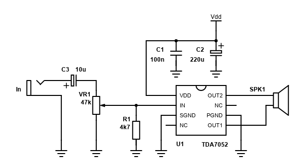
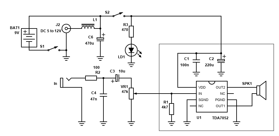
My schematic below shows how simple the circuit is. I've also included a resistor to ensure the input impedance is predictable, a volume control using a 47k potentiometer and DC blocking capacitor C3 to stop the potentiometer becoming noisy over time due to DC in the audio input. They are not completely necessary, and my original schematic did not show them, but I recommend to keep them to avoid problems as they'll add very little cost and take only a small amount of extra room.
| # | Type | Quantity |
|---|---|---|
| U1 | TDA7052 | 1 |
| U1 | (optional) 8 pin DIL DIP socket | 1 |
| R1 | 4k7 ohm Resistor, ¼W Metal Film, 1% | 1 |
| C1 | 100nF Capacitor, 50V+ Ceramic X7R or MLCC | 1 |
| C2 | 220µF Capacitor, 16V+ Electrolytic | 1 |
| VR1 | 47k ohm Lin Potentiometer | 1 |
| C3 | (optional) 10µF Capacitor, 16V+ Electrolytic | 1 |
| In,Vdd,SPK | 2.54mm header 6-pin (cut as needed) | 1 |
| cable, connectors | ~ |
The capacitors C1 and C2 are for power supply decoupling and are considered necessary. C1 should be a 100nF (0.1µF) ceramic capacitor and located closest to the TDA7052 pins. C2 should be an electrolytic capacitor of 220µF or higher with a voltage rating of a few volts higher than your supply voltage (i.e., 10V for 6V supply, 16V for 12V supply, 25V for 15V supply).
Resistor R1 can be any 4k7 resistor which is 5% tolerance or better. Metal film resistors are best, however since the resistor is not directly in the signal path a cheap carbon resistor will also be fine.
The volume control is made up of VR1 which is a variable resistor or potentiometer. It should be 47k linear as the linear potentiometer loaded with R1 will give a good logarithmic response. In order to stop it becoming noisy after time, DC blocking capacitor C3 should be 10µF electrolytic capacitors rated for 16V or better in case your source has a DC offset. The positive lead should be facing away from the potentiometer.
Note that the TDA7052 has no DC offset at its input pin. I measured with a multimeter and the DC voltage at the input pin is exactly zero, so no input capacitor is needed between the potentiometer and the TDA7052, further reminding us just how simple this circuit is!
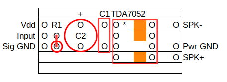
Below is a layout for the amp for beginners using Veroboard or 'stripboard'. The layout is simple, but you will need to use a track cutter to cut three traces where the amplifier chip is soldered onto the board (shown by the orange squares) but be careful to leave the trace between pin 3 and pin 5 connected as this is where the two grounds meet. If your power and signal ground meet elsewhere in your system, you can also cut this trace in order to avoid ground loops.
The layout does not include a volume control (or C3 before it) or any LED power indicator. If you have some understanding of electronic circuit design, then you can easily incorporate these onto the board. This will require additional wiring and/or track cutting for the preferred layout.
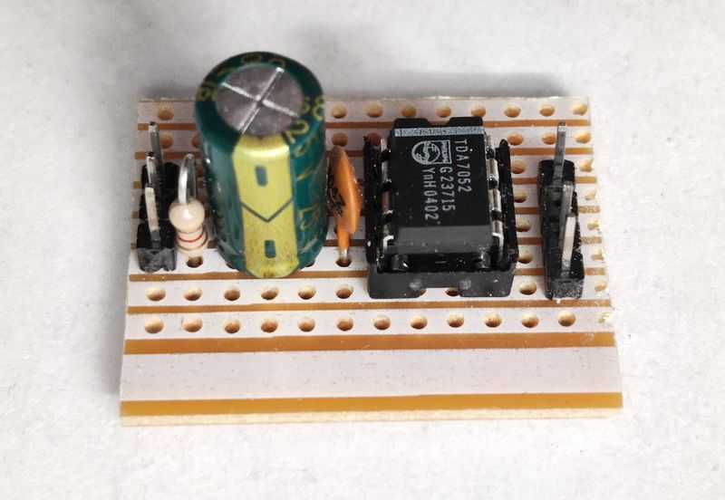
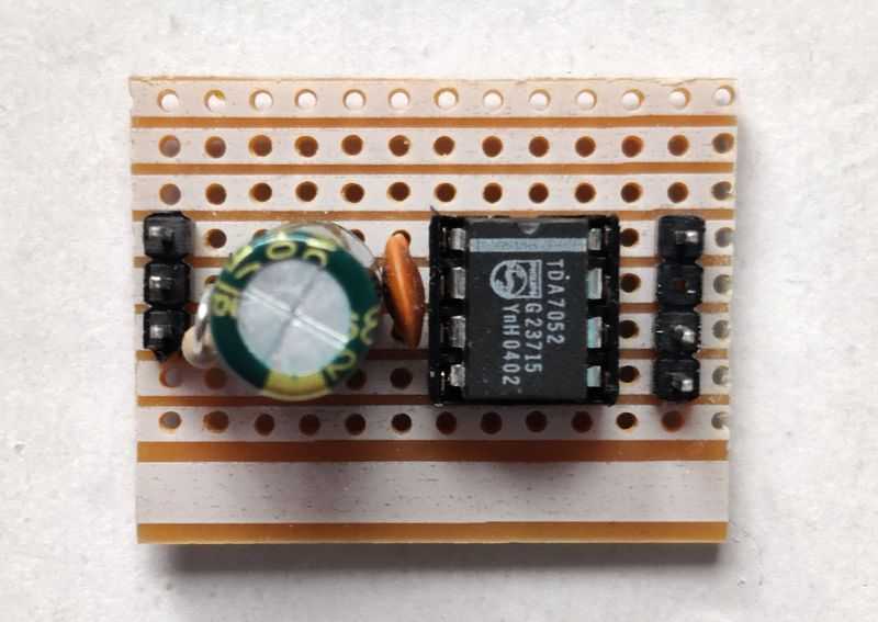
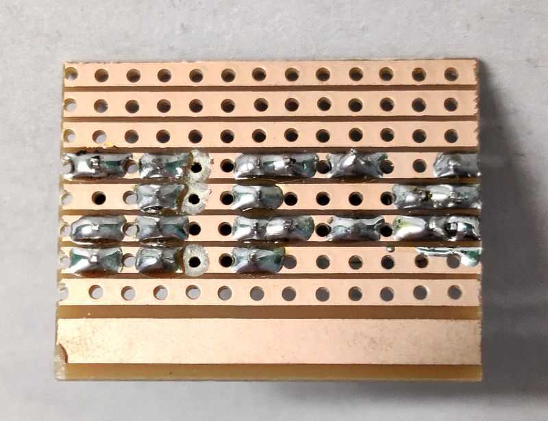
My stripboard version I made for testing is shown below and it can be seen that the layout is as above. It took 10 minutes for me to solder!
Construction
The orange squares show where the tracks MUST be cut. If this is not done sufficiently, the amp will not work. You can do this with a proper track-cutting tool available at some retailers (this is recommended) but if you cannot get one, it is possible to cut the tracks by carefully using a drill bit or cutting the copper tracks with a knife.
Use a multimeter (or if you do not have one, a battery and led/bulb/buzzer circuit) to make sure there is no short between the cut tracks to ensure that they are cut fully.
Soldering is required to fix the components to the board. If you're a beginner and have not done this before, by all means practice. Soldering on stripboard can be a little challenging at first as it is easy to short the adjacent tracks if too much solder is used. Once this is done, it is difficult to correct without desoldering braid or pump, so avoid using too much solder and touching the other tracks with the iron. I suggest having desolder braid handy as it really saves time to use it to mop up solder when you do make a mistake.
One thing I've noticed (when trying to de-solder them) is the TDA7052 chips do NOT tolerate lots of solder heat. My recommendation is to buy 8 pin DIL sockets and solder these instead because they'll forgive you more easily if you apply too much heat.
After soldering, use your continuity tester to ensure that adjacent tracks are not accidentally touching. You can also check the leads of most components to see if they are electrically connected to the stripboard tracks.
The 0.1µF (or 100nF) C1 is a ceramic capacitor. These will allow the leads to bend to fit the 5mm gap on the layout above. The 220µF capacitor C2 is an electrolytic capacitor, and it may need some lead bending to fit the 5mm spacing. Don't worry if it does not fit flush to the board. THE CAPACITOR MUST BE CONNECTED THE RIGHT WAY ROUND, otherwise it's bubble, burst, or launch itself off the board, especially with higher voltages (i.e., 9-12V). On both the schematic and stripboard layout the positive side is shown. On the capacitor itself the negative lead is usually clearly labelled on the capacitor can, or if it's a new capacitor the positive lead is usually the longest lead.
The 4k7 resistor R1 is mounted vertically to avoid the need for an extra jumper if it was mounted horizontally. To mount it vertically, simply bend one end 180 degrees back on itself. The two lead ends should now easily fit in adjacent holes in the board. Vertically mounting resistors like this is often fine and I've seen it done in equipment too.
This amplifier is intended to power an 8 ohm speaker from a 6V power supply. You can push it with a higher voltage for a bit more power, but the datasheet contains no output information for such and giving the TDA7052 is a DIP chip with no heatsink, I would not go beyond 9V. The maximum voltage of 15V is intended for higher impedance speakers such as 16 ohm and 32 ohm.
I do not recommend driving 4 ohm speakers with it, but if you do (and I have done), then keep the supply at 3V, or 5V at the most otherwise the chip will likely overheat.
When wiring the loudspeaker, do not ground it. The TDA7052 uses BTL (Bridge Tied Load) which gives you up to 4 times the power with two amps (which are integrated in the TDA7052) in to the same load impedance. If you short the loudspeaker to ground, do not expect it to work. It may not even protect itself from a repeated loudspeaker short condition.
As a last note, make sure you put the TDA7052 in the right way before you solder it. The diagram shows an asterisk on the chip. This asterisk indicates pin 1 and the chip itself should have a small dot, line or semicircle indent on the side where pin 1 is. Pin 1 will be in the top left. Insert the chip the wrong way and it will not forgive you and you will have to get a new one, trust me, I've (foolishly) done it!
The TDA7052, whilst great, is not bullet proof, so avoid mistakes such as connecting the power supply the wrong way round, soldering or inserting the DIP chip the wrong way round or shorting out the loudspeaker connections. To avoid this for loudspeaker connections, do not use 3.5mm style connections to the loudspeaker because they may briefly short it whilst inserting/removing whilst the amp is powered on. Use spring clips, banana plugs, DIN sockets or (since it's low power) phono and mini DIN sockets are also fine.
Power
The datasheet is brief on power details. It states 1.2W output for a 6V power supply into 8 ohms. This is at a 10% THD (distortion) though, which will sound terrible, so expect less in reality. This figure though is only quoted at 6V. By increasing the power supply to 9V, you'll get more power - perhaps 2W, however you should install a stick on DIP heatsink to avoid it overheating. It certainly capable for portable applications and you'll find 1W of power can be quite loud.
Given this is a single supply chip (positive and ground), there are many options for powering it.
My original build used 8 of 1.5V AA cells (or UM-3, M, RX6), giving 12V. That's a little high though and 6 1.5V AA cells (or UM-3, M, RX6), giving 9V, will be more portable. As the TDA7053 can operate on as little as 3V, you can use less cells, but bear in mind the maximum power will be less. For longer life, but more size/weight feel free to use larger cells such as C or D size. These days though, lithium ion rechargeable batteries will give more power in a smaller space and add that rechargeable flexibility. A 7.4V lithium battery will work well. Whilst a 9V PP3 battery will also work, they are intended for low current applications, and they will not last as long and end up a costly way to power the amp.
Power through USB is also an option. USB gives 5V and most PC USB ports now are capable of supplying more than 1A of current, however even the standard 500mA USB current will get a single TDA7052 running fine. At 5V though you can only expect 1W of power at best and at this power, the TDA7052 will draw 400 to 500mA, so running a stereo pair may be a challenge.
The best power is available from a dedicated power supply. My original build was a DIY PSU that utilised an internal mains transformer from an old Ghetto-Blaster, with rectifier, but this has safety challenges.
Wall/brick power supplies are easy to find though, and you may even have some unused ones laying around! Aim for 9V for the best power into 8 ohms, 12V in to 16 ohms. These should have a rated output of 500mA or better for a single TDA7052. Double that for a stereo pair. I recommend increasing C2 to 1000µF to bypass and smooth the voltage further.
Gain
The gain is fixed and cannot be changed by changing/adding like many other amplifiers. The fixed gain of 39dB is rather high, representing a voltage gain of around 90 times! This is calculated as 10^(dB/20) = 10^(39/20) = 89.1.
Because of the high gain, noise performance won't be fantastic, and you may find that the volume control is rather sensitive if you use a potentiometer that has a low value or too high value.
Despite the troubles with the high gain though, in reality for use as a portable amplifier it works quite well as you might be using a phone or portable mp3, CD player or whatever as the source which is designed to drive headphones and you won't have to turn the volume all the way up on the portable device in order to get good volume output on your TDA7052 driven speakers.
TDA7052 Building a 'system'
The above schematic is the amplifier with a volume control and that may be all you need to integrate with an existing system. If you're building a new system though you may want to add extra components:
- A power switch
- A power LED
- A low pass filter to remove frequencies above 20kHz
- Batteries and/or
- A power supply
- Optional power supply filtering
The diagram above shows how you could build a mono system. S2 is the power switch, and LD1 with current limiting resistor R3 is a simple power LED using a small 3mm or 5mm LED of whatever colour you prefer.
J2 and S1 are part of a DC power jack. These jacks usually have three pins. One is positive, the other is negative. It's more common that the outside of DC barrel connectors is negative, so do double check! The third pin is usually connected to the barrel outside until you push a plug into the socket.
By connecting a battery box to the third pin, this means when there is no DC power plug pushed in the socket, the batteries are available, but when the DC power jack is pushed in, the batteries are disconnected. If the outside of the DC plug is negative, then that means you need to switch the negative side of the battery box.
L1 and C6 form a high pass filter that helps remove any audible whine noise from cheap switching power supplies. It won't completely eliminate noise, but it can help make what you have usable. You can exclude L1/C6 if you see no need for them, just replace L1 with a wire link. I suggest a value of 2.2µH to 10µH for L1. It should be able to handle at least 1A, preferably 1.5A or better. Power inductors that can easily handle this current should be easy to find at most electronic retailers.
On the input side, R2 and C4 form a low pass filter. The cut off frequency is about 34kHz which means frequencies above that will be attenuated. This helps with harmonics caused by GSM noise when your mobile rings or receives a message nearby.
All grounds must be connected to a single point star, bus or star of stars. Don't create loops or you'll get hum or whine noise when operating on mains powered equipment.
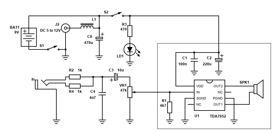
If you want to make a mono amplifier but have a stereo source (often the case), you will need to union the left and right channels as most material (music, TV etc) will not sound its best or be complete when you only connect the left or right channel. You can do this by using two 1k or higher resistors as shown above (R2 and R4). To save components, the low pass filter can be combined with the summing resistors by dropping the value of C4 to 4.7nF.
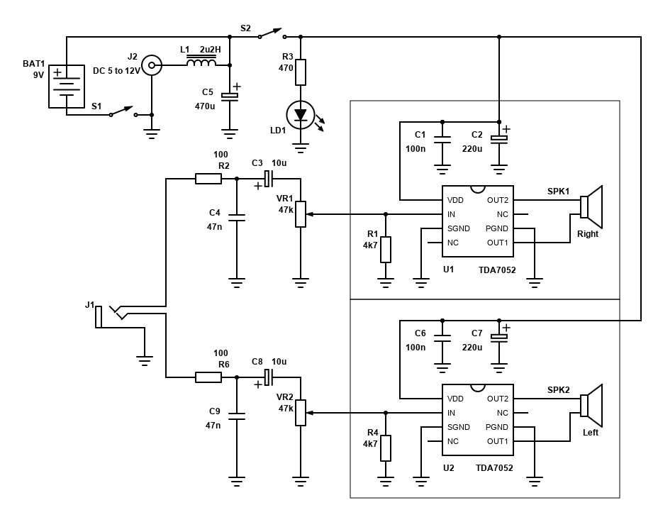
A stereo system can be built almost as easily by duplicating the amplifier, speaker and input side components. In the schematic above, VR1 and VR2 should be a dual linear potentiometer so that turning it adjusts the volume to the same level for both left and right channels.
Performance
For the cost and simplicity, the TDA7052 is a pretty good solution to the portable, battery operated amp problem. Years ago, when I was first starting out in DIY electronics (around 2001 and 2002) I used a stereo TDA7052 amplifier every day at school and sixth form. The speakers I used were 2.7 ohm with a 4 ohm tweeter in parallel for improved high frequency response, in an open baffle design to improve portability. It's not an easy load for a small amplifier, but the TDA7052 survived even with 12V despite this load being well above recommendations.
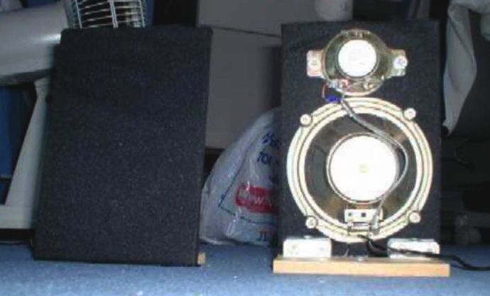
Battery performance is good too. My system was stereo, but it still ran for weeks on a good set of AA batteries, and it would still run when the batteries become quite flat (just with less top volume).
My set up gave me good sound (even with some low frequency response too) and has plenty of volume for most circumstances (except for those who demand music at high, often distorted, volumes). For me, it gave my laptop the sound boost needed when playing DVDs which are too quiet for its internal amp and speakers (laptops in that era had rubbish sound), and also allowed me to play music with friends from my MiniDisc player.
I later built a stereo TDA7052 in a smaller form factor for my student bedroom during university, see here.
TDA7052A and TDA7052B application
Quick facts TDA7052A
- Power output: 1.1W into 8 ohms at 10% 1kHz distortion with power supply 6V
- Gain: 35.5dB (variable via DC control) - max gain of 30dB in my application
- Power supply: 4.5V to 15V single supply
- Datasheet available here
Quick facts TDA7052B
- Power output: 1.0W into 8 ohms at 10% 1kHz distortion with power supply 6V
- Gain: 40.5dB (variable via DC control) - max gain of 34dB in my application
- Power supply: 4.5V to 15V single supply
- Datasheet available here
A variant of the TDA7052 that is more available nowadays is the TDA7052A. The TDA7052A is very similar in terms of performance and pin out, but it will not work in the same circuit.
There is also the TDA7052B which work in the same circuit as the TDA7052A but appears to have more gain and slightly less power handling.
There are also surface mount variants of these chips - TDA7052AT and TDA7052BT which are smaller, but can only output around half the power as their DIP brothers (0.55W for both the TDA7052AT and TDA7052BT). The circuits for these are similar but I won't cover them.
Comparing the circuit to the TDA7052, the TDA7052A needs two additional components at minimum. This is because there is a DC volume control input which needs to be connected to ground via a 1µF capacitor. The input pin for the TDA7052A (unlike the TDA7052) has a DC offset at its input pin too, meaning that a 470nF capacitor is also needed in series with the input and the input pin.
The extra components and larger board needed due to that is the disadvantage. The advantage is the DC volume control pin 4 provides us some flexibility over the basic TDA7052 above:
- The volume control potentiometer can now go directly to this dedicated pin
- The volume control input is logarithmic, and more accurate than a log potentiometer. This allows use of common linear potentiometers for volume control
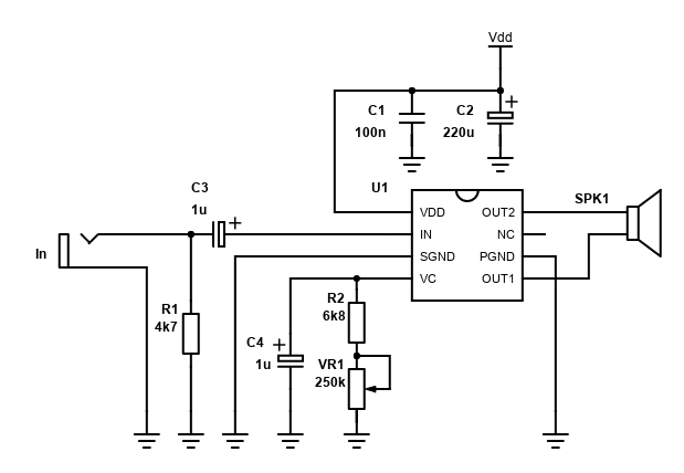
Here's the adjusted schematic for a simple amplifier, with a sensible maximum gain of around 27dB for the TDA7052A, or 32dB for the TDA7052B:
| # | Type | Quantity |
|---|---|---|
| U1 | TDA7052A or TDA7052B | 1 |
| U1 | (optional) 8 pin DIL DIP socket | 1 |
| R1 | 4k7 ohm Resistor, ¼W Metal Film, 1% | 1 |
| R2 | 6.8k or 5.6k ohm Resistor, ¼W Metal Film, 1% | 1 |
| C1 | 100nF Capacitor, 50V+ Ceramic X7R or MLCC | 1 |
| C2 | 220µF Capacitor, 16V+ Electrolytic | 1 |
| C3,C4 | 1µF Capacitor, 16V+ Electrolytic | 2 |
| VR1 | 250k Lin Potentiometer | 1 |
| In,Vdd,SPK | 2.54mm header 8-pin (cut as needed) | 1 |
| Heatsink, cable, connectors | ~ |
Like the TDA7052, there are power supply bypass capacitors needed - C1 and C2. C1 should be a 100nF ceramic and as close to the TDA7052A pins as possible. C2 is an electrolytic capacitors of 220µF or higher. Electrolytic capacitors are polarised so the positive lead in must go in the positive voltage supply. This is the longest lead if the capacitor is new, but check the casing anyway as the negative lead is usually clearly marked.
C3 is an input capacitor. 470nF is suggested in the datasheet and combined with the 20k input impedance this will give a high pass cutoff frequency of 16.93Hz - that's calculated by 1/(2πRC) - 1/(2 × 3.14159 × 20000 × 0.00000047).
C3 should be a polyester or electrolytic capacitor. Polyester is known to have the best audio quality but on an amplifier of this size you're unlikely to notice the difference and an electrolytic will be fine. Avoid a ceramic for this capacitor. If you have 1µF electrolytics, feel free to use those instead (that's what I did on my board). The positive lead must face the chip.
R1 provides a DC path to ground for the audio signal, and also gives the amplifier a predictable input impedance for whatever source you connect. This resistor is suggested as 5k in the datasheet but 4.7k is a more commonly available value that will work just as well.
Below is a layout for the amp for beginners using Veroboard or 'stripboard'. The layout is simple, but you will need to use a track cutter to cut three traces where the amplifier chip is soldered onto the board but be careful to leave the trace between pin 3 and pin 5 connected as this is where the signal and power grounds meet. If your power and signal ground meet elsewhere in your system, you can also cut this trace in order to avoid ground loops.
Note that resistor R2 is mounted vertically in order to keep the layout small and simple. Simply bend one of the leads almost 180 degrees back and feed both leads through the holes on the board and carefully solder, ensuring you leave a small gap between the board and the body of the resistor to avoid overheating when soldering.
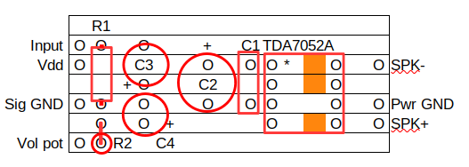
The volume control potentiometer itself I have not included on the board as the size/shape will vary. See below for more details on the volume control.
DC volume control and gain
The DC volume control is at pin 4. The TDA7052A produces a voltage of around +1.125V at this pin, as well using the current at this pin as a volume reference.
This VC pin gives a convenient way of adding a volume control that is accurate and will not go noisy over time.
Note: It is not possible to control multiple TDA7052A chips with a single volume control by connecting the VC pins together. I've tried and unfortunately this just makes both chips distort. If you want a stereo amplifier, my first choice would be the TDA7053A instead, which does allow you to connect the VC pins together, or alternatively just use a dual gang linear potentiometer with the 6k8 in series for each channel.
Capacitor C4 is a 1µF electrolytic that is used for power on muting. How this works is the capacitor initially looks like a short circuit, keeping the TDA7052A muted. The capacitor will then slowly charge by the 1.125 volts on pin 4, leaving the only path to ground via the resistor R2 and potentiometer VR1. For a longer mute time, you can increase the size of this capacitor.
The datasheet shows a 1M ohm potentiometer to allow control of the volume of up to 30dB. 30dB is a reasonably usable gain, but it's a bit on the high side at 32x. A 250k potentiometer instead will give a gain of around 27.2dB (23x) which I found more suitable for plugging into laptops, phones, MP3 players etc.
If you need the higher gain, a 500k potentiometer could be considered an alternative to 1M. With this, at the highest setting, the gain rises to a higher 30x (29.5dB), but the volume range felt easier to control than the 1M potentiometer.
The additional 6.8k resistor R2 in series with the potentiometer I added to avoid a 'dead' spot on the potentiometer where you have to turn it from its minimum a little more than expected before the TDA7052A has enough current to unmute itself. Feel free to leave this resistor out though if you wish. The gain measurements above include the 6k8 resistor in series with the potentiometer and with both 250k and 500k potentiometers the handling was good - allowing the amplifier to fully mute when the volume potentiometer is turned fully anti-clockwise, and only a small turn clockwise is needed from there to allow signal through.
If some signal is still coming through in your source though when the volume control is set to its minimum, reduce the value from 6k8 to 5k6 or maybe lower still.
The potentiometer is not shown on my layout, but it should be wired like this so that turning it clockwise turns the volume up. This is the front view:
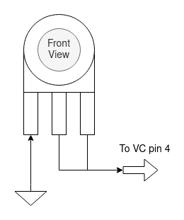
The ground lead (first pin from the left) should be connected to input ground - either back to the board or your input socket.
To avoid noise when touching the potentiometer, consider grounding the metal casing of the pot too. This will not be needed if the potentiometer is mounted on a grounded metal case though, and you'll probably get away with not needing to ground the case either if you have a plastic knob on the potentiometer.
With no volume control connected (only the capacitor), the TDA7052A will still work with a gain of about 37x (31.4dB) from what I measured. If your volume control is elsewhere - you can consider leaving out any resistor and potentiometer from pin 4 completely, or cap the gain to your preferred maximum using a fixed resistor e.g., 1M, 470k or 330k (1M giving the highest gain).
The unconnected VC pin (except capacitor) is somewhat off the maximum possible gain quoted of 35.5dB (typical). To get this gain maximum gain, you actually need to apply a voltage of 1.4V or higher to the VC pin 4. You could do this by connecting a resistor to the positive input, as suggested in the TDA7053A datasheet below. I suggest though that you don't wire the volume in this way unless you need the maximum gain as the resistor needed will depend on your supply voltage and I prefer the flexibility of being able to plug the amplifier into whatever power supply is available.
Note that the TDA7052B has a different gain range (it's higher), the gains quoted above are for the TDA7052A but based on my experiments with a TDA7053A (which has similar gain) the maximum gain with no potentiometer or voltage source connected to VC will be about 64x (36dB).
I couldn't measure the voltage offset for these potentiometers as I found the voltage varied with/without a signal. The datasheet isn't great on details for the volume control, but it does show a gain vs voltage graph that gives you an idea of the voltages needed.
Being able to drive the volume with a DC offset voltage opens up the possibilities of actually driving the volume in other ways - such as with a microcontroller such as PIC or Arduino with a DAC chip, or just any digital potentiometer (does not need to be audio quality).
Power and performance
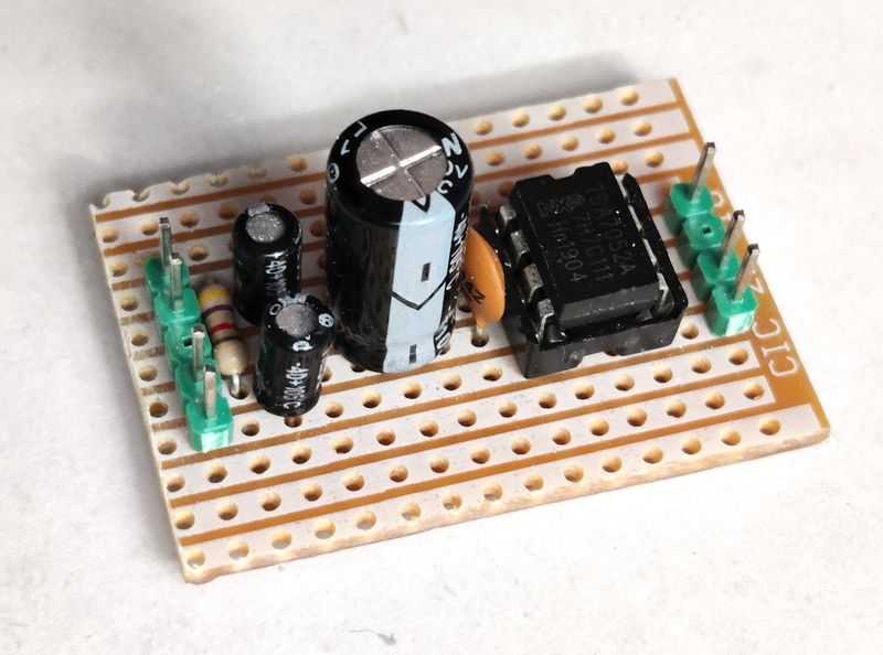
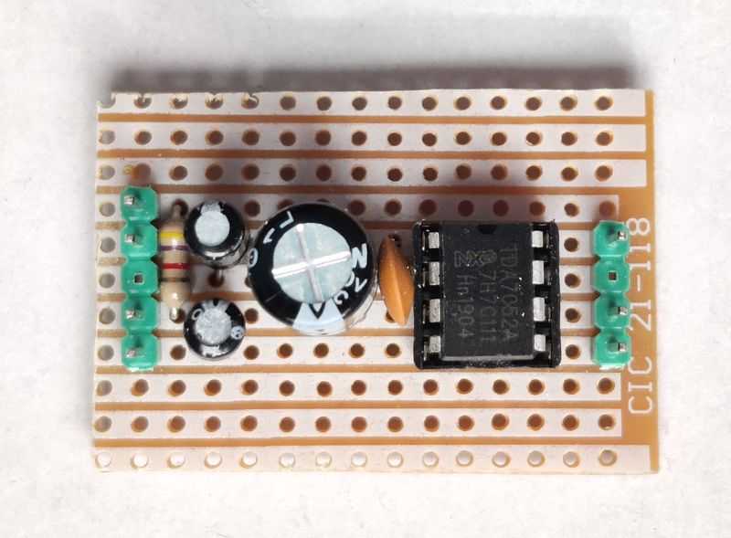
Below is my actual build. It only took less than 20 minutes to solder up. It's small, convenient, and works well.
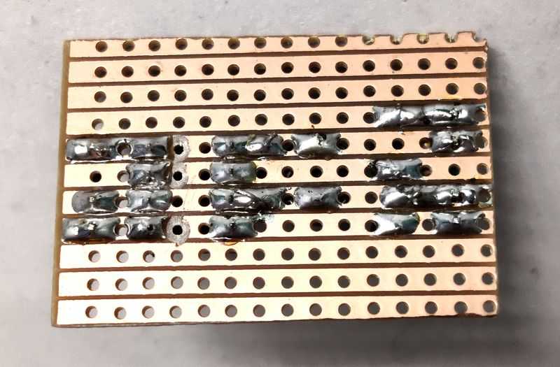
On the underside there's a few more solder joints to make, but still really easy.
Performance/power is like the TDA7052, but perhaps a little worse under testing. It's still quite good for an old but small 8 pin DIP chip with such simplicity.
Your power supply should be in the region of 6V for driving an 8 ohm speaker. Under testing, I found a higher voltage of 12V and even 7.5V caused the chip to enter some protection mode where the output was reduced with added hiss (not clipped though). With 6V the chip happily provided the speaker signal at a higher power before it gave up than I could get with higher voltages.
I found it could drive 4 ohms too, but it will get hotter still and voltage may need to be reduced below 6V to 4.5V.
Testing music seemed fine. Using a smartphone as a source via it's 3.5mm headphone output, I found it quite capable, and the 250k volume control potentiometer had a nice range to it.
Compared to the TDA7052, the TDA7052A needs a couple more components and a slightly bigger board but considering how quick and easy it was to build, and cheap it is to buy (including components), I think the TDA7052A still makes a great beginner project for building your own powered speaker.
For a stereo system, as mentioned, consider the TDA7053A instead which will need less components, however you could use two TDA7052A chips using a similar technique as the stereo TDA7052 system above. You need a separate volume control on each chips VC pin but this can be solved with a single dual gang potentiometer to control the volume of both amplifiers simultaneously.