
TDA1514/TDA2040 Surround Sound Amplifier - Mark 2 - Surround Sound Amplifier Remake
Part 1 - Ideas and Design
For more than 2 years, my first surround sound amplifier remained pretty much the same from when it was completed. The performance from it was very good, and the time it lasted was proof to myself that I could make an amplifier that works from various circuit designs, and a good knowledge of safe electronics.
In 2003 though I wanted to make some improvements to the aesthetics, power and internal layout.
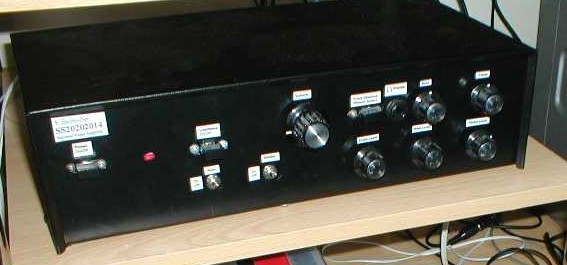
In these few web pages, I will show how I converted my old amplifier (this:)
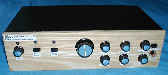
and gave it a bit of a facelift:
Original Quote, (This was on my electronics page earlier):
"If I have enough money, I am planning a very nice amp. It's going to be using single TDA1514 amps for the main channels and should reach 40W per channel of power.
Rear would be 2x LM1875's and one LM1875 for the centre channel, each capable of about 30W. The preamp may be a separate module so I could use two smaller boxes rather than
trying to squeeze all the electronics inside one big box. Unlike my other large amplifier project (above), I will try to provide details of the building process, and make it
much more commercially acceptable (better looks, neater wiring etc). This time I will also get the boxes before I buy any of the components (strongly recommended by the way
as the last project was built electronically actually months before I got the box).
Designs"
The original plan above was to keep the original intact and still in working order and build a totally new design. I would have loved to do that, but unfortunately finances were not too great at the time and things were mounting on top of me, so the new amp was going to be a lower budgeted, time limited build, but without the inevitable failure like software engineering projects under the same constraints. ;-)
At one point, it was actually never going to happen, but at the time, I needed to do something to cheer me up a bit, so I scraped together what I could and went and purchased the first parts. The LM1875 idea was scrapped, as I had TDA2040 chips already.
It was a very sad time to break up the original and take it apart and split it into parts that will be re-used, and parts that go in the electronics drawer, to be re-used at a later date.
So, what was re-used, and what wasn't?
Well, first I am going to start with a small description of the old amplifier - what it had for instance...
The old amp was powered by two 20W TDA2040 amplifiers to the front channel, one 20W TDA2040 amplifier driving both rear channels, and one 14W TDA2030 amplifier driving the centre. It contained tone controls, a loudness filter, an active volume control and a simple surround sound decoder.
Other smaller features included rear and centre pre-ins, power switches for rear and centre amplifiers, volume levels for all channels, a headphone output and a rather unique fan and controller which would speed up when the amplifier got warm. It was all powered by one 80VA toroidal transformer, except for the fan which was powered off a small EI transformer.
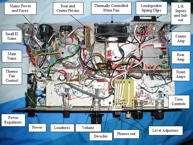
The picture pretty much describes the originals layout and components quite well. As can be seen from this picture, the original amplifier had quite a messy finish. It wasn't down to messy wiring as such, but more down to the overall layout, which did mean large jumps were needed and in areas the cables would be of high density and the best I could do was cable tie them. A re-make was aiming to be a neater job.
Ok, so onto what I could re-use, and what would be upgraded (I'm going in a clockwise direction):
- Mains Power and fuses. Well, they were all unwired. I reused the fuse holders, but used different IEC mains connectors - ones that had earthed aluminium shielding round them (pulled these out of an old dead PC AT PSU).
- Rear and centre Pre-ins. These were not reused, as that rear pre-in would convert stereo to mono (to suit that single rear amp), but also because there wouldn't be enough room on the planned changes to the back panel.
- Fan (and thermo controller) - ditched, my new design would have an external mounted heatsink so heat removal wouldn't be such a problem.
- Loudspeaker spring clips - reused, nothing wrong with them (binding posts were outside my budget).
- Inputs and sub out - again, reused.
- Centre Amplifier (1x TDA2030) - Ditched, I decided that more power, and furthermore...
- Rear Amplifier (1x TDA2040) - This single 20W rear amplifier became the new centre channel amplifier.
- Front Amplifiers (2x TDA2040) - Reused for stereo rear amplifiers. The front would be replaced them with much bigger amplifiers, of the TDA1514 range - 40W each.
- Tone Controls - These done their job fine, so were reused.
- Level Adjusters - Some were reused, but there were a few noisy ones, which were replaced.
- Phones out - Reused.
- Decoder - Changed for a new one (stereo)
- Volume - Changed for a better potentiometer and used passive control.
- Loudness - Not needed and didn't want to re-make it on a different board.
- Power Switch - This was changed to a rotary switch.
- Power Regulators - Only the +/- 15V for the input circuitry were reused, all other components were not.
- Main Transformer - This 80VA Toroidal was capable of providing the power to the +/-15V regulators, and the rear and centre power amps, so was reused. It could not however supply the much greater power demands of the new front amplifiers, so another 80VA toroidal was purchased.
- Small EI Transformer - This was removed with the thermo-fan controller.
- And finally - The Case itself - Actually was reused :)
Things added:
- A stereo width controller - gives me nice adjustments to the front channels.
- New rear surround sound decoder (based on the width controller)
- New centre surround sound decoder (based on the original, just on a different board)
- Powerful TDA1514 front amplifiers.
- Another 80VA toroidal transformer (18V AC).
- An almost complete remake of the power rectification and regulation circuitry - including much bigger DC smoothing capacitors.
- Blue LED's :)
What was the new design going to be like?
I had to think about it quite a bit. Before I planned to reuse the original case - I had ideas of many different layouts and even designs using two cases - one for input manipulation, and one solely for the power amps. I had no 'set in stone' layout, and it was actually after the first few boards were complete that I decided I could use the old case and make a neat job.
The first board design (that is the width controller, and surround sound decoders) was done carefully, because I was not certain where I was going as such - so this board was designed to be compact and thin so there was room to put other controls on either side of it. Once I had that board, and the original amplifier boards, the original tone controls, and a good idea where the other boards and components were going to go - I could start laying with their positions in attempt to brainstorm my mind into the best solution. You will see the final solution soon, but here is what my brainstorming came up with:
This was an initial design, so the front was not quite thought of, that came together as I went along - but this is basically where each of the main circuit boards went. At the time I had no plans of reusing the headphone out board, that was something that sprung to mind latter. My mind had come up with the good idea of using the case height to double deck the amplifiers so they would all fit on a rear mounted heatsink. This proved very effective. Apart from the heatsink, the back of the amp was unchanged, with the loudspeaker connectors, inputs and sub outputs and the mains inputs and outputs and fuses were all in the same place!