
LM386 DIY Guide - Simple Utility Milliwatt Power Amplifier
Contents
Recommended Experience : beginner
LM386 application
The LM386 comes in several variants.
Quick facts LM386
LM386N-1
- Power output: 325mW into 8 ohms at 10% 1kHz distortion with power supply 6V
- Gain: 26dB default, variable from 19dB to 46dB
- Power supply: 4V to 12V single supply
- TI Datasheet available here
- JRC Datasheet
LM386N-3
- Power output: 700mW into 8 ohms at 10% 1kHz distortion with power supply 9V
- Gain: 26dB default, variable from 19dB to 46dB
- Power supply: 4V to 12V single supply
LM386N-4
- Power output: 1W into 32 ohms at 10% 1kHz distortion with power supply 16V
- Gain: 26dB default, variable from 19dB to 46dB
- Power supply: 4V to 18V single supply
All variants are more-or-less the same. The LM386N-1 being the most common and is the best for battery operated devices as it's optimised for 6V. LM386-4 allows a higher supply voltage for driving more power into high impedance loads (such as 32 ohms). All variants will have a package dissipation limit of 1.25W though, so even the LM386N-1 will drive an 8 ohm speaker to 700mV with a 9V supply.
Guide
Other than an earlier write up I never really completed, I've lacked any interest in the humble LM386 because for a simple power amplifier, there are great alternatives. The TDA2822M and TDA7052/TDA7052A I'd consider superior, with the latter being ultra-simple.
These chips are now obsolete now though, but the LM386 lives on even though it was first conceived in the 1970's. It's still produced as of 2022 and you can buy it from nearly all electronics retailers I know.
It's mainly a Texas Instruments (TI), previously National Semiconductor chip, but also other manufacturers/clones such as UTC386 by UTC (Unisonic), NJM386 / NJM386B from JRC New Japan Radio, now part of Nisshinbo, GL386 by Hynix. Some chips are just labelled 386 - not to be confused with the Intel computer CPU from the 80's.
I'll be featuring the LM386N variants which come in an 8-pin DIL package which is DIY friendly. You can also get LM386M chips in surface mount SOIC packages. These have less power dissipation though, which will affect their power output.
The LM386 amplifier is capable of 325mW (that's around 0.3W) from 6V and has a variable gain from 26db to 46db (20x to 200x). The datasheet says it's 'opamp', but I would say it's not and consider it only as a power amplifier because none of the conventional opamp circuits could be applied to it due to its different pinout and it having internal resistors that set the gain (meaning it can't have unity gain either). It's performance in this configuration would also likely be worse than a dedicated opamp such as the LF321/µA741. I have seen it used in DIY line level applications though, and I see some appeal in using it as a single supply opamp if the application works within its limitations, but really, it's intended as a power amp.
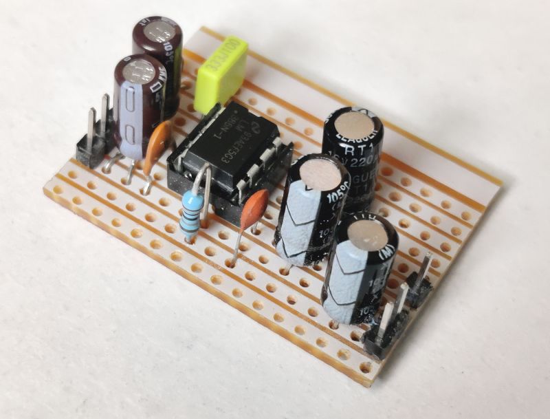
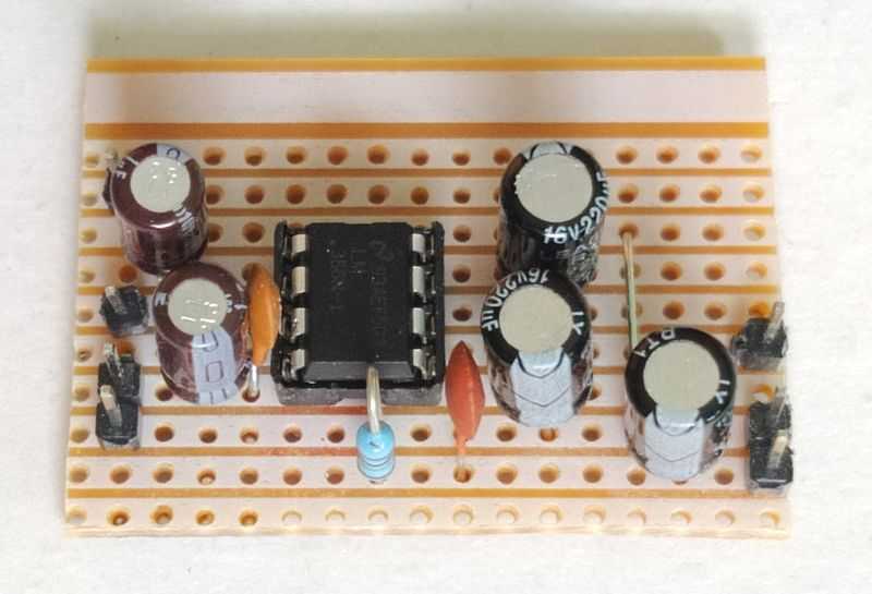
I have encountered and used the LM386 amplifier once years ago as part of a kit, but I've no idea what happened to it now, so I purchased some new chips so I could design a layout and test the amplifier.
I'd consider it as a 'utility' amplifier. The LM386 is ideal for driving speakers like these:
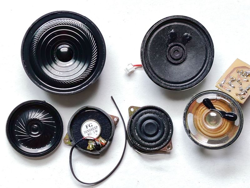
It comes from the days of AM radios, cassette tape players, CRT TVs, bedside clock radios etc., and would have done the job for low end / portable applications such as these. Whilst it'll work fine for music, it's not Hi-Fi and does not have enough power to produce much bass. Given its limited output into 8 ohms, it's more suggested for other applications such as toys, intercoms, amateur radio, or perhaps small PA systems such as a lift (elevator) telling you what floor you're on etc.
It also seems to have popularity as a practice/portable guitar amplifier where bass and loud volume isn't required (it'll still go pretty loud for practising though!).
It's intended for audio, but it is not Hi-Fi or professional though. Lack of power is the obvious reason, but it also does not have wonderful noise performance and THD is 0.2% at 1kHz, compared to a good chip amplifier which will typically be 0.05% or better.
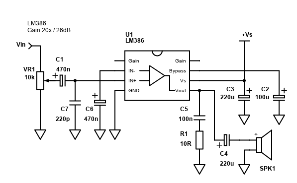
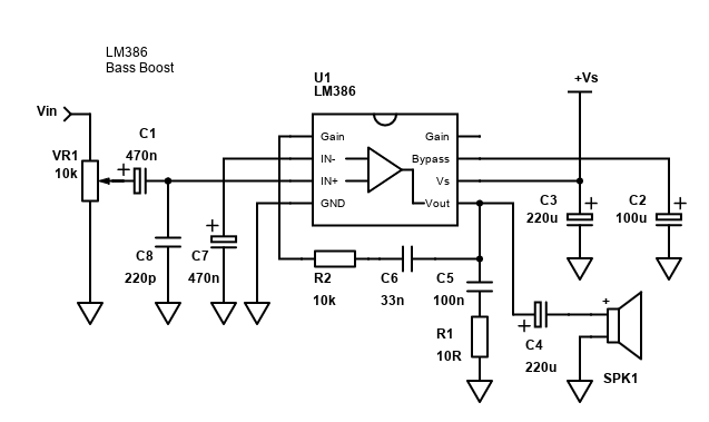
As can be seen from the schematic, the component count is quite low for a recommended design - 7 capacitors, 1 resistor, a variable resistor and the chip itself.
LM386 basic application
| # | Type | Quantity |
|---|---|---|
| U1 | LM386 | 1 |
| U1 | (optional) 8 pin DIL DIP socket | 1 |
| R1 | 10 ohm Resistor, ¼W Carbon, 5% | 1 |
| C1,C6 | 470nF (0.47µF) Capacitor, 16V+ Electrolytic | 2 |
| C2 | 100µF Capacitor, 16V+ Electrolytic (25V+ for LM383N-4) | 1 |
| C3,C4 | 220µF Capacitor, 16V+ Electrolytic (25V+ for LM383N-4) | 2 |
| C5 | 100nF Capacitor, 50V+ Ceramic X7R or MLCC | 1 |
| C7 | 220pF Capacitor, 50V+ Ceramic X7R or MLCC | 1 |
| VR1 | 10k ohm Log Potentiometer | 1 |
| Vin,+Vs,Spk | 2.54mm header 6-pin (cut as needed) | 1 |
| Cable, connectors | ~ |
This is the circuit which has a gain of 26dB - a reasonable value that will certainly be able to amplifier an auxiliary signal from a phone or PC to the LM386's maximum power.
The basic application above has a few more components over and above the datasheet version, but I recommend them all for stability. So, what do these components do?
VR1 and C1 are at the line level input. VR1 is a potentiometer and is ideally a 10k log (logarithmic) pot, but the value is not too critical and 22k or 4.7k will also work. For guitars, higher values are preferred such as around 100k. C1 is technically optional and it's there to block DC offset from both the source which would shift the DC offset at the LM386 output, reducing power as a result. It also blocks any small DC offset from LM386's input pin 3. Blocking the DC will reduce the rate of the potentiometer becoming scratchy over time.
C1 with the input impedance of the LM386 will form a high pass filter. The input impedance is 50k, as can be seen on the internal schematic diagram, page 1 of the datasheet. The calculation for the -3dB (50%) cut-off is 1/(2πRC) - e.g., for the 0.47µF (470nF) capacitor, that's: 1/(2 × 3.14159 × 50000 × 0.00000047) = 6.7Hz - well below any frequency response this amplifier would be expected to handle anyway!
The positive pin should face the LM386 if using a polarised electrolytic capacitor. A 0.1µF (100nF) capacitor would cut off around 32Hz - still very acceptable, but bear in mind that capacitors in the audio path should not be ceramic - use some film capacitor instead. If you use electrolytic, the positive pin should be facing away from the LM386 as any DC offset from the LM386 will be small (I measured just 9.2mV), but the DC offset at the source is unknown.
C7 acts with the series resistance of the potentiometer to form a low pass filter. It'll attenuate any frequencies in the kHz to MHz range which will help reduce radio interference and GSM noise, as well as help reduce feedback from the output if you have a high impedance source. C7 is optional and not shown in the standard circuits, but you'll find small capacitors at the inputs of many amplifiers (such as the TDA1514) to improve performance. You can use a ceramic capacitor here, and it should be as close to the chip as possible. I did find myself that adding this gave a cleaner signal at the output when measuring with the oscilloscope. It also removed oscillation with no input connected.
The inverting input pin 2 is ground reference, but via another 470nF / 0.47µF electrolytic capacitor C6 (you could also use 100nF or 220nF film capacitor). This allows the amplifier to have a little more power output as the input stage is biased correctly via the internal 50k resistor. If the little extra power doesn't matter and you'd rather save cost and size, feel free to leave C6 out and connect pin 2 directly to ground (per the datasheet). If you use electrolytic, the positive pin should be in pin 2. Most other chip amps (including the TDA2822M) already show their inverting input grounded via a capacitor in this way.
Pin 4 is the power ground. You should have one ground connection with all ground connectivity going here to reduce noise/hum i.e., don't daisy chain ground connections. Star ground is ideal, but for reasonable performance using a ground strip as a bus on the stripboard will work.
C2 and C3 are bypass capacitors and should be as close to the LM386 as you can get them. They reduce hum and improve stability. If you are running the LM386 purely on batteries and will never connect it to another power supply, you can reduce the size of these capacitors. Adding 100nF ceramic capacitors in parallel with these may help with performance on mains too, but I found they were not making an improvement.
Note that C2 and C3 are electrolytic capacitors. The positive lead must be at pin 6/7 with the negative lead in the ground. These capacitors can explode if connected the wrong way and take you by surprise because it might not happen immediately!
At the output pin 5, C4 is required between that and the speaker. This is because the output pin will have a DC offset which will be about half of your supply voltage - i.e., with no audio signal (or DC) at the input and a 12V power supply, you would measure 6V at pin 5.
C4 blocks this DC offset from shorting to ground through the speaker voice coil, allowing only AC to pass. Again, C4 forms a high filter, this time with the impedance of the speaker itself. Again, the calculation for the cut-off is 1/(2πRC) - e.g., for an 8 ohm speaker and C4 of 220µF it's: 1/(2 × 3.14159 × 8 × 0.00022) = 90.4Hz.
This means bass response will be affected. Bass is reduced with the 220µF capacitor suggested. For many cases, that's just fine for a utility amp as the speakers often connected to them cannot reproduce these frequencies very well anyway. If you do need better bass response though, increase the size of C4. At 470µF the cut off is 42.3Hz, and at 1000µF it's 19.9Hz (about where human hearing stops anyway). Larger value capacitors are physically larger and cost more to buy though so there's a disadvantage.
Finally, C5 and R2 are for stability. This is known as a Zobel network, and many amplifiers need them for stability. You should include it as the amplifier will likely oscillate without it (an oscillating amplifier will heat up, waste power and perform badly). The Zobel network's function to the amplifier is to make the speaker appear to have a predictable impedance at high frequencies. C5 should be a 100nF (0.1µF) ceramic or film capacitor. R5 can be carbon or metal film and a low value - around 10 ohms (not 10k ohms!).
Construction
The main schematic for the amplifier above is a recommended improvement over the circuit featured in the datasheet. This suggestion requires 7 capacitors and 1 resistor.
The circuit is simple to construct, and it can be done easily on stripboard/Veroboard or breadboard, but the best results for performance and size is to use a custom layout. I've added options for a stripboard layout that could be constructed by novice builders. I've left out a custom PCB layout as it wouldn't result in a worthwhile reduction in board size, however if you are building a high gain amplifier you should consider a custom PCB layout.
When building, make sure that you insert the LM386 chip in the board the right way and as well as the electrolytic capacitors the right way round. If you do apply power to it up connected the wrong way, consider it dead! Pin 1 follows the standard for all ICs and is at the top left corner. The notch on one of sides indicates pin 1. Nothing else is particularly critical, the amp will run with the cheapest resistor and capacitors you can buy.
The only resistor is at the Zobel network and 5% carbon is fine, since it's not passing the audio. If you are altering the gain though (see below), I suggest 1% metal film resistors for better quality (less hiss). Capacitors C1 to C4, as well as C6 are electrolytic capacitors. C2 to C4 must all have a voltage rating greater than your supply voltage - so 16V or higher (25V for the LM386-4 into 32 ohms).
C1 and C6 can be changed to film capacitors if you prefer and reduced to anything 100nF or higher (I only suggest 470nF as electrolytic capacitors typically don't come in smaller sizes, and I even used 1 µF capacitors in my build test).
DC blocking capacitor C4 affects frequency response it forms a high pass filter with the impedance of the speaker. See above for example and formula to calculate it, but a 220µF capacitor is a reasonable compromised between size/cost and performance with small speakers.
Bypass capacitor C2 I've suggested as 100µF, but if you want to order multiple quantities of 220µF capacitors, you can use one for C2 too. You can also get away with smaller values, but I'd suggest no lower than 10µF. This capacitor is for bypassing the ½ voltage bias made internally by the two 15k resistors.
Also bear in mind that bigger value for C4 will result in a more expensive to buy and physically larger capacitor. This may not fit on my layouts so adjust as required. I would advise against going larger than 1000µF as charging these during power on or speaker connections will put stress on the amplifier.
Including the LM386 chip, there's 10 components in total. If you don't need a volume control, exclude VR1, or replace VR1 with a fixed resistor between the input pin and ground for a fixed attenuation of the input signal.
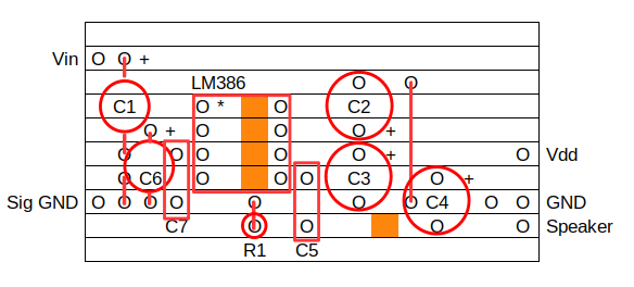
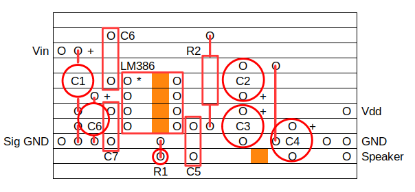
Stripboard layout
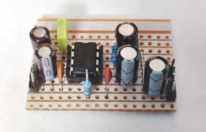
Below is my suggested layout for the simple mono LM386 on SRBP stripboard/Veroboard or similar. This would allow you to build the circuit in less than an hour.
You would need to obtain a stripboard cutting tool or use alternatives like carefully using a drill bit (in a manual or low speed battery operated drill) or knife to make cuts in the copper strips where the dark orange squares are. All four tracks should be cut between the IC pins, and a fifth cut is needed between C4 and C5.
Solder the LM386 first, or ideally solder an 8-pin DIP socket. Then work outwards from the chip so you solder the small components in the correct places first. Once soldered, trim off the excess leads, but keep them.
The offcut leads can be used for the unmarked wires in red on the diagram. These are known as jumpers.
After placing these, finally solder in the large electrolytic capacitors C2, C3 and C4 as well as C1 and C6.
C2 I've located in the spare area that was above C3 with a jumper to ground. This is because both C3 and C2 should be as close to the LM386 chip as possible. So that they fit in the board area, make sure you use 16V to 25V electrolytic cans with a body diameter of 8mm or less. The lead pitch and means they won't sit flush to the board, but it is OK for them to be a couple of millimetres above it.
I've not included VR1. Potentiometers will come in different sizes and probably will be annoying to solder on to stripboard. You could create a separate board for these or wire them off a board using a point-to-point method.
To make the board as small as possible, some things are a squeeze. You should not space components away from the LM386 too much or it will be suspectable to noise. Also cut the board to size before testing otherwise long strips will pick up noise too.
Adjusting gain
The voltage gain can be easily adjusted from 20 times (26dB) to 200 times (46dB). The datasheet shows both configurations and the example above show the suggested gain of 20x as this will be sufficient for most input sources, such as laptops, phones, mp3 players, cassette players and radio modules and in most cases, you'll not need to change it. If you do need more gain though (such as a guitar practice amp, or microphone / intercom), the gain can changed in several different ways:
- Adding a resistor and capacitor between pins 1 and 8.
- Adding a resistor and capacitor between pin 1 and ground.
- Adding resistors that work in parallel with the internal resistors, such as from pin 1 to pin 5 (like the bass boost)
By using different techniques, the gain can even be lowered from 20 to about 9 (less than this and the amplifier will become unstable).
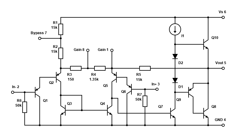
Let's look at the first technique first. Above is a reproduction of the internal schematic of the LM386.
These components work with the internal 1.35k, 150 ohm and 15k resistors - R4, R3 and R5 in my replicated schematic above. With no extra components, you can work out the gain with the formula of 1 + (2 × (R5 / (R3 + R4))). In the basic example, that's 2 × (15000 / (150+1350)), which gives 21 (datasheet says 20, but it means 20 times above the input).
During testing, I measured different RMS voltage gains across my 5 test chips, averaging 21.8x in the default 20x gain configuration. The chip with the lowest gain was 21.36x, with the highest being 22.32x. They'll be some inaccuracies with the test/equipment I used, but I repeated the test three times with different levels of input voltage to get an average and there was a clear pattern that the chips had different gains. This indicates there could be a tolerance difference with the internal resistors affecting gain (the 1.35k resistor being just 1% lower would give almost 22x). In reality, this won't make much difference as you'll unlikely to hear that difference if building a stereo amplifier.
Putting a capacitor between pins 1 and 8 bypasses that 1.35k resistor internally, giving a gain of 1 + (2 × (15000 / 150)) = 201. Feedback through this path is AC, hence the capacitor will look like a shortcut for AC signals but keep the DC gain unaffected.
The capacitor between these pins needs to be quite large though - 10µF is suggested, otherwise low frequencies will start to have a high impedance and follow the path of the internal resistor instead (giving the amplifier a boost to treble only).
To convert to decibels, use 20 × log(gain) - e.g., 20 × log(20) = 26dB, 20 × log(200) = 46dB.
To convert from decibels to the voltage gain ratio, use 10(dB/20) - e.g., 10 ^ (26/20) = 20.
To get a gain of 32dB as an example, first work out the ratio - 10 ^ (32/20) = 40. Rearranged the formula from 1 + (2 × (15000 / (150+Rg))) = gain gives: (15000 / ((gain − 1) / 2)) − 150 = Rg.
With our target gain of 40 (32dB): (15000 / ((40 − 1) / 2)) − 150 = 620. 620 ohm resistors are E24 resistor values so you can get them, but the nearest E12 value is either pick 560 ohm, or 680 ohm, giving gains of 43.25 (32.7dB) or 37.14 (31.4dB).
Another way of adjusting gain is how the bass boost circuit works. This puts a 10k resistor in series with a capacitor between the output pin 5 and the gain pin 1. Ignoring the capacitor for now, how is that 10k resistor affecting gain?
It's working in parallel with the internal 15k resistor R5 between the same pins. So, we'd have the resistance of (R5 × Rext) / (R5 + Rext), e.g., (10k × 15k) / (10k + 15k) = 6k. Our gain is now 1 + (2 × (6000 / (150+1350))) = 9, or 19dB. That reconciles to the datasheet bass boost response graph (at high frequencies). During testing with a 10k resistor I measured 9.4x gain.
9x / 19dB gain doesn't sound like much, but this is a small amplifier and will reach its limits quite quickly. As an example, when driving an 8 ohm speaker the LM386 can output 250mW at the point of distortion. The voltage to the speaker would be V = √(0.25 × 8) = 1.4V RMS. Divide that by 9 and you get 157mV. Pretty much any Smartphone, Laptop, MP3 Player etc will be able to output an audio signal of this voltage, though you might prefer a little more gain if watching quiet videos, for example.
Finally, to mute the amplifier, you can short the gain pin 8 to ground. If you want a microprocessor to do this, an easy way is to use an NPN transistor with the emitter in ground, collector in the LM386 pin 8 and base connected to the microprocessor via a 1k to 10k resistor. The microprocessor will need to share the same ground (connected at one point only).
Inverting input
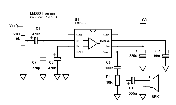
The LM386 gives the option of two input pins - a non-inverting (pin 3) which is used above, and an inverting (pin 2).
Typically, you would ground one of them (ideally via a capacitor) and connect the other to your input source. The AC at the input would then go positive and negative to that ground reference on the other pin.
I've not tested it, but apparently the inverting is quieter. If you use the inverting input though, the output will also be inverted. This may never be a problem if the speaker connected to the LM386 is the only output, but if the LM386 is driving satellite speakers with something else driving a subwoofer, or a similar multiple speaker set up, the signal phase will matter. The problem can be resolved by connected the speaker + terminal to GND and - terminal to the LM386 output though!
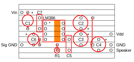
Below is a stripboard layout for the basic inverting amplifier. Actually, this layout is 0.1inch / 2.54mm smaller because C1 and C6 can be arranged better.
Bass boost
As mentioned already, we can use a resistor R2 and a capacitor C6 in series from the output pin 5 to the gain pin 1 to provide a low frequency shaping feedback path. At higher AC frequencies, the capacitor to pin 1 has a lower impedance and will start to flow down this feedback path - lowering the amplifier gain at these frequencies. Lower frequencies however start to get blocked by the capacitor C6, forcing the gain of these frequencies towards the default LM386 gain of 26dB.
Below is a screenshot of the response, straight from the data sheet.
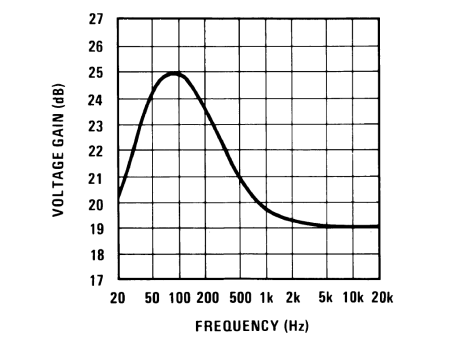
Do note though that the gain doesn't quite reach 26dB as the low frequencies are rolled off again by capacitor C4 in series with the speaker, which will have a -3dB (50%) cut off at 90Hz. If you really want boost below the 90Hz, increase the size of C4.
In a way, I actually recommend this circuit for most applications as it helps the sound a bit on those small speakers - i.e., you'll be able to pick out a 'little' low frequency there, instead of barely anything at all. Noise is also reduced. This is not a big bass boost, so it will still go quite loud before clipping, but not as loud as having no boost.
If you need to, you can still alter the gain, but you'll need to calculate or simulate the response curve with the adjusted gain. The suggested values however provide the minimum stable gain of 9x with the 10k resistor suggested. Do not go lower than 10k.
It's easy to adjust the basic stripboard layout above to add the additional components, see below for my suggestion.
Upon adding them, the result works as expected, and you can hear an improvement in low frequency response. It's also still able to go quite loud from a Smartphone audio source.
You can also use the bass boost circuit with the inverting configuration. Simply swap the connections to pins 2 and 3 around.
Performance
The LM386 isn't considered a Hi-Fi amplifier, and we shouldn't expect miracles. Certainly, the design in the datasheet and many other web pages is also focused for ease of build and low cost, and the design I've featured is also considering cost.
Into 8 ohms though, it sounds fine. With sensitive speakers, it'll go pretty loud too. As it has a very limited power output though (less than 1 watt RMS), it will not handle bass very well and clip on transients in most music types. With a 1kHz signal, I found the amplifier (an LM386-1) would deliver 483mW into 8 ohms with 9V with no clipping, reducing to 161mW when powered with 6V.
Into 4 ohms, the amplifier is limited. It just doesn't have the current capability on the output to drive such a low impedance load, and most of the power it draws trying to do so just becomes heat. You can see figure 3 in the TI datasheet for its poor 4 ohm peak-to-peak output voltage. If you do use 4 ohms, keep the supply voltage 6V or lower and bear in mind you'll get about 250mW into 4 ohms only (peak-to-peak is about 2.8V, therefore RMS voltage is 1 / (2 × √2) × Vp-p = 0.99V, RMS power = Vrms2 / RL = 0.245W).
For a small project though, where you are close to the speakers (like small PC speakers) or just need utility sound (not music, TV or games), it will have a use. I'd say this is a great beginner amplifier.
I don't own/play or know anyone who plays a guitar, so I can't comment on its merit as a practice amplifier, but it's well featured online with several designs.
LM386 building a 'system'
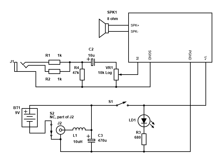
The schematics and layouts above deal with just the amplifier itself. If you want to build a speaker system though, you'll need a few more components to control the amplifier, ensure that the power supply is adequately filtered, and the system is properly grounded.
The amplifier is primarily intended for battery operation, so you'll probably want a battery box in your system. Do not use a 9V PP3 battery - they are supposed to power very low power devices and if you try to power the LM386 with it - it'll work OK at low volumes, but as you turn the volume up the battery voltage will drop considerably and drain quickly. Instead, use 6x AA or AAA batteries, or 4x batteries to get 6V (this will still go quite loud). If you want to use Li-Ion (i.e., 2x 18650s or 14500s), you'll need a BMS (battery management system) to handle charging and over-discharge protection.
When the batteries are flat though, you'll probably want the option of running from a PSU. 6V and 9V PSUs with DC 2.1mm or 2.5mm plugs are common and ideal. The schematic above shows an inductor (L1) and capacitor (C3) after the PSU input though to help reduce noise and improve stability. L1 can be 1µH to 47µH, with higher values doing a better job of filtering, but have a lower current handling (especially transients).
External PSU DC power should never be applied in parallel with the batteries so that both voltage sources are powering the circuit at the same time. Some DC jacks come with three pins so that the ground lead from the battery box can be connected to this third pin. When no plug is pushed in to this socket, the pin is connected to the ground output as a kind of normally closed switch. This will allow the batteries to power the amp. When a plug is pushed in to the socket though, this third pin gets disconnected, safely isolating the batteries from the external power.
The jack and its internal switch are shown as J2 and S2 on my schematic. The positives of both the DC jack and the battery box can connect together as you only need to disconnect one side (i.e., the negative) to safely protect the batteries.
System power should be switched on/off with a switch. A simple latching SPST switch, rocker or toggle switch in series with the positive power lead (S1) will do. Switch the positive side in case there is an external loop through the negative side and the power is pulled through the input ground instead.
To indicate power, an LED (LD1) should be added, with an appropriate current reducing resistor (R3) so it doesn't burn out. 680 ohms suggested should allow most LEDs to light up from 6V to 9V, though it may need to be reduced for the lower voltage or a brighter output. The resistor can be before or after the LED (i.e., at the anode or cathode), it does not matter. Some switches can have LEDs built in but check if the switch has a resistor included or not.
At the input side, most inputs are stereo, so I suggest a 3.5mm stereo jack socket (J1), and two 1k resistors (R1 and R2) to sum the left/right channels to mono. A capacitor in series with the audio (C2) blocks any DC offset from your source to the volume control, which will help stop it becoming noisy / scratchy over time. The resistor to ground before that (R4) provides a DC path in case your source needs a little load to work.
The volume control (VR1) is shown in the original schematic, but also again here as I did not add it to the stripboard layout. A single gang 10k log potentiometer should be easy to find, but they vary in sizes and mounting options. I suggest getting the larger ones as they are easier to mount, but even the thread on those is not long enough to mount through the thickness of most wood.
Try to place all input components, including the volume control as close to the LM386 board as possible.
For a stereo system you'll need 2x LM386 boards and a dual gang potentiometer. The 1k summing resistors would no longer be required, but you should have the DC blocking capacitors and resistors to ground before them for both channels. You'll need two speakers too, of course.
I suggest the TDA2822M for a simple stereo system, or TDA7266 / TDA7297 is even better if you can get either of these chips.
BTL Bridged LM386
Bridging the LM386 isn't something recommended, because of current limitation I've already mentioned (see performance into 4 ohms). If you need more power, use a different amp! The LM386 is old and inefficient and won't run happily bridged in most configurations as it's easy to exceed the limits.
However, if you understand the limits, and don't expect miracles, you can bridge it and be able to get around 1W of power into 8 ohms from 6V (at 10% distortion). To bridge it - simply make one standard (non-inverting) LM386 and a second inverting LM386 - schematics above. Connect the + speaker terminal to the output of the first amplifier, and - to the second inverting amplifier.
You have to consider power dissipation in the design. It's limited to around 600mW on a hot day (~35°C) and this is why the normal single ended amplifier should not have a power supply exceeding 9V into an 8 ohms speaker.
In the basic single ended application, if you've only got a 5V or 6V power supply and an 8 ohm speaker, dissipation is halved at around 250mW. The chip can give around 300mW RMS power to the speaker in this configuration.
Peak-to-peak output voltage is listed for 4 ohm speakers, in the datasheet, and it shows a shallow line so you can expect dissipation to more than double, and power output to be less than double as driving lower impedance is noticeably less efficient. In a bridge amplifier the 8 ohm speaker would appear as a 4 ohm speaker to each amplifier driving it (as current is doubled).
So, with power dissipation more than doubled to 600mW or higher, you can see that the power supply rail limit for the BTL amplifier would be 6V, for an 8 ohm speaker. Don't even think about BTL into a 4 ohm speaker (or lower!).
If your PSU is max 6V and speaker min 8 ohms impedance, each chip should just be within its limits and the power output should nearly reach 1W RMS (I measured 990mW). With 5V supplies being plentiful these days, it could be a useful USB powered amplifier.
As a battery powered amplifier, this may seem attractive too as it lets you use less cells. But bear in mind it's efficiency is considerably worse and quiescent will double too, so battery life will be less than driving an 8 ohm or higher speaker.
A small benefit of the BTL amplifier is you usually don't need the output capacitors for speaker. This is because both amplifiers are driven by the same supply voltage and will generate the same ½ DC offset (e.g., 3V from a 6V PSU). As both sides of the speaker should now have a 3V DC, no potential difference between the two sides of the speaker should be present and no DC current will flow through its coil.
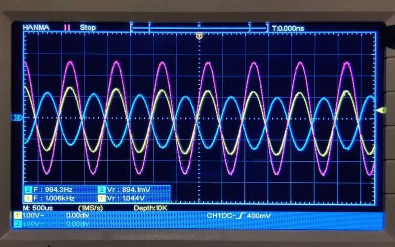
In my testing though, I found the DC offset at the output of the inverting amplifier to be 200mV DC higher than the non-inverting amplifier. This isn't ideal and I found performance better when keeping the DC blocking capacitors in both amplifiers, hence I suggest to include them. If you have closer matched amplifiers though, you might get away without requiring these capacitors.
The RMS power measured at each oscilloscope probe when referenced to ground was also different.
Note that in bridge configuration, neither speaker terminal can be connected to ground in this configuration, so I wouldn't recommend connecting an external speaker unless both speaker terminals are isolated from ground, or if a plug/socket is used, the two poles should not be allowed to short each other when inserting the plug (3.5mm connections can do this so best avoided).
Also note that gain doubles for a BTL amplifier as the same input voltage is now driven by two amplifiers, so the voltage gain will be around 40x (32dB).
The stripboard layout is basically above - take the standard layout, and the non-inverting layout. You can omit two ground pins from each board as the speaker ground is no longer needed, and the remaining one ground pin should be taken to a star ground. The star ground will be important. Connect the grounds from both boards to a single point, where the power supply/battery ground and the input ground also meet.
Split the source signal in two by using 1k resistors in series between the source and each amplifiers input capacitor C1.
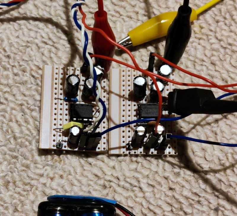
My test seems to work, however I found the inverting amplifier ran a bit hotter, probably because of the DC offset unbalance. Again - do not use a supply voltage above 6V, do not use 4 ohm speakers (8 ohm absolute min), do not connect the speaker to ground, and do not expect miracles - power will be limited to 1W and distortion will be worse at all power levels. Bear in mind these limitations when building a system - it may be a user connects a higher voltage PSU, or a lower impedance speaker and your amp dies as a result!
You also lose the frequency shaping bass boost with this BTL configuration. You could add it, but it adds more performance risk as the capacitor and resistor must be very closely matched or one amplifier will be doing more work than the other, forcing the other to sink current (which it's not supposed to do!). 1% resistors could be OK, but capacitors are typically +/-20% tolerance at best.
Not that it's Hi-Fi but also bear in mind that distortion (crossover distortion mainly) will be worse in a bridged amplifier. This would be noticeable on high frequencies, so it would make a poor BTL tweeter amplifier! I also found hiss worsened in BTL mode.
Despite the flaws, it sounded ok when playing music into a 4 inch, 8 ohm speaker and gave a bit more volume than it would have otherwise into the same speaker with one amplifier.
If you want BTL performance with more than 6V supply voltage though, seriously look at other amplifiers. The TDA7266 / TDA7266M are great alternatives that are already BTL to start with and they are very simple to build and much more capable.
Conclusion
I never properly featured this amp before because it didn't seem that interesting. Despite its ripe old age though, it is still produced, and you should be able to buy it somewhere all over the world.
If you build the circuit straight out of the datasheet, in any layout you feel like, you might be left disappointed though. The extra components I've suggested help, and the layout matters too.
Get these things right though, and it's an easy to build amplifier that should be capable for many 'utility' operations or small speakers that are near to you (such as laptop/PC speakers). It's a great beginner project that might get you into DIY electronics (particularly audio), just like it did with me (along with the TDA2003 and TDA7052) back when I was a teenager, late 1990's.
Of course, there are superior amplifiers. For a low voltage amplifier, a PAM8403 will give more power from a lower voltage. You won't learn as much though by buying a pre-made module and hooking it up. Many of the other chip amps I've featured may be interesting to you too (such as TDA7266M / TDA7266 / TDA7297)... still, it's worth buying the LM386 as it is cheap and interesting to build as a first hobby amplifier.
References:
LM386 TI datasheet
NJM386 New Japan Radio datasheet
Electrosmash - LM386 Audio Amplifier Analysis
Stephan's Virtual Shack - Engineer's Corner: Fun with Chip Amps LM386
JohnAudioTech (YouTube) - Make the PERFECT LM386 audio amplifier?
ESP - LM386, LM380 & LM384 Power Amplifiers