
Getting started with a ADAU1466 14 in 18 out board
I’ve been investigated DSP solutions for my home audio and whilst there are many options, what I wanted to look for is a DSP that could potentially replace and enhance the functionality of my DIY surround sound amplifier.
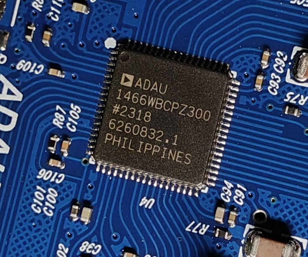
This blog entry is about the ADAU1466 version, but should be applicable to the ADAU1452 version. At the time of writing though, the ADAU1452 was only $4 cheaper, so hardly worth the saving for a DIY project.
The prospect of a DSP with many inputs and outputs allows me to achieve:
- A 5.1 channel analogue input
- Several stereo inputs
- Digital inputs such as SPDIF and I2S for connecting Bluetooth boards, CD Players etc.
- Multi-channel volume controls, input selectors, splitters and combiners
- 5.1 channel output
- Bi-amplified speakers – three-way or even four-way with subwoofer outputs, with the ability to test different crossover frequencies and curves
- Parametric EQ, Tone Controls, Room EQ
- Other DSP functions such as virtual surround, Midnight mode, Automatic Volume Control
The ADAU1466 is a big step up from the common cheap ADAU1401 / ADAU 1701 boards which often have just one stereo input and two stereo outputs. They’re ideal for simple 2.1 systems, or a simple bi-amplified speaker, or boom box as they only cost about £12, but not much more.
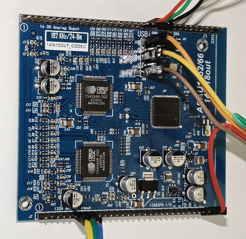
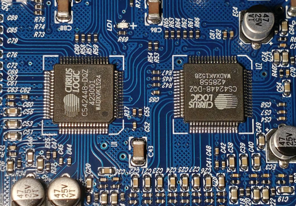
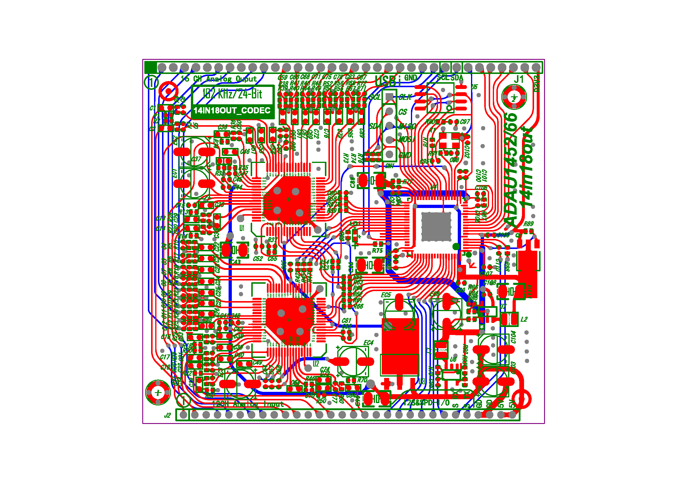
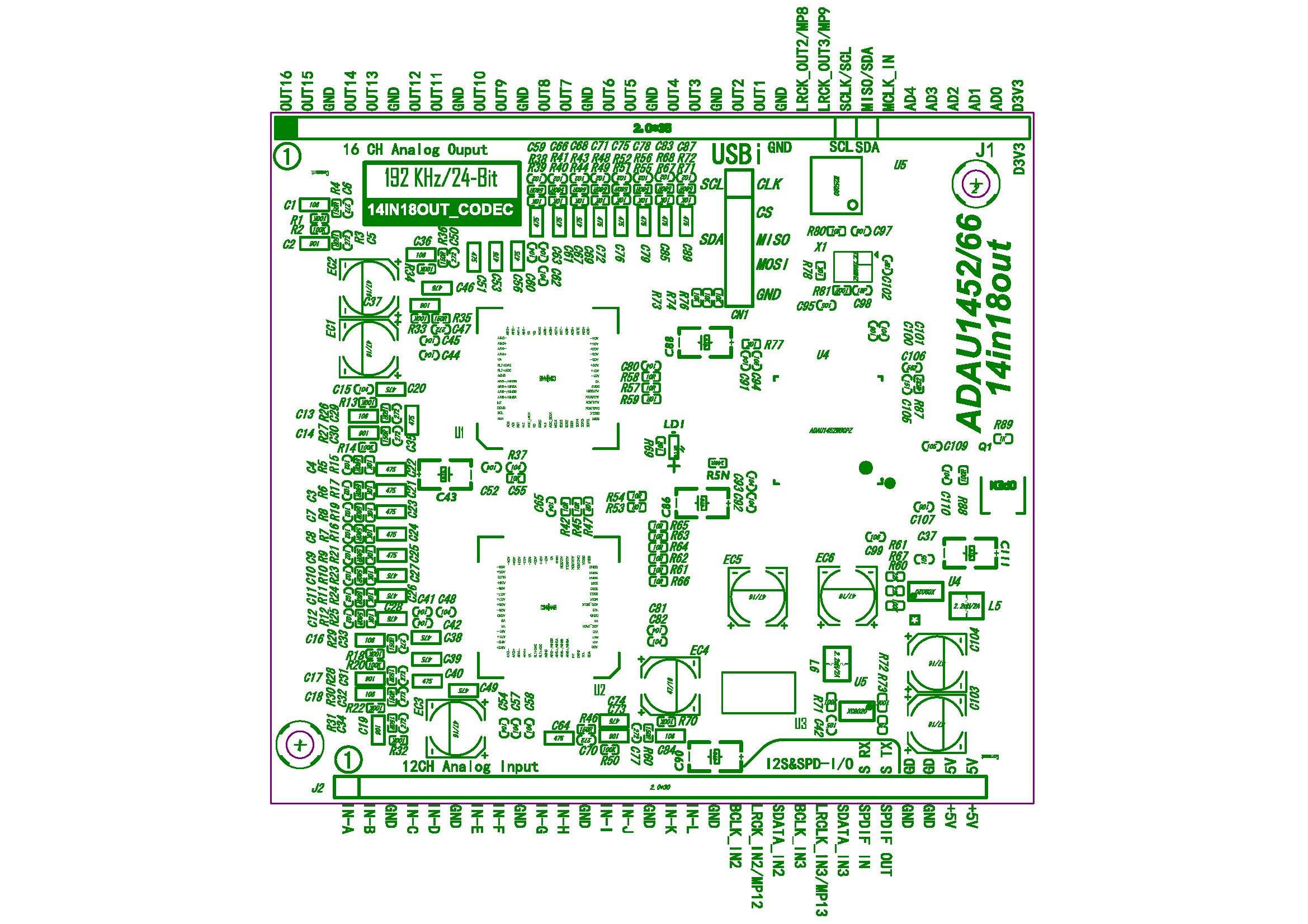
ADAU1466 on the other hand supports 192kHz sampling rate with 24-bit resolution and has much more processing power and memory, but if you need analogue inputs or outputs than you need to look for boards with added ADCs and DACs (analogue-to-digital and digital-to-analogue converters). The board I brought has two (now obsolete) Cirrus Logic CS42448 chips, each having six ADCs and eight DACs. They should be good quality.
All analogue inputs and outputs are AC coupled via capacitors. I'm unsure of their quality or precise value as I measured them in circuit. A schematic of the inputs and outputs is below.
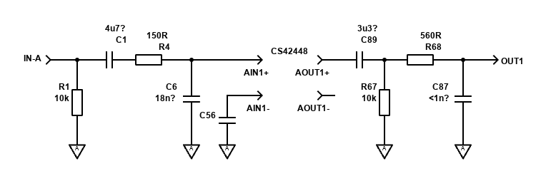
Note that there are 12 analogue inputs (the other 2 are digital), and 16 analogue outputs (other 2 are digital). They are all wired up the same way.
The cost of the board was about £45, but be prepared to spend more because:
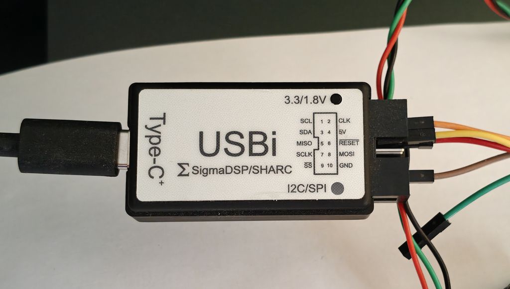
- You’ll need a programmer, which is usually not less than £27 itself. I got the "USBi Emulator ADI SigmaStudio USB C version"
- All the headers are not standard 2.54mm ‘DuPont’ connectors. They are 2.0mm instead. Unless you fancy soldering the cables directly, you’ll need a “Dupont 2.0 Housing Plastic Shell 2.0mm Pitch” kit, and “2.0mm 40 Pin Male Single Row Pin Header Strip”. I got this for about £6 when combined with other things to get free shipping. These are hard to find, but AliExpress store “excellence electronic” has both.
- Once you receive the above and start crimping cables, you’ll realise the smallest 0.25 (AWG28-24) tooth in the tool is too big. One for JST connectors (0.08 should work. Another £10.
If you want to control the DSP too, you’ll need various switches / potentiometers and potentially a microcontroller for the most versatile control (this is what I’ll be using).
For testing, the DSP board worked fine from the 5V power off the USBi programmer. For the end project though, you’ll want a 5V PSU to power it. It’ll need about 350mA but aim for something capable of giving more.
Still, it’s worked out cheaper than a Mini-DSP or other options and being its own board means you can integrate it directly in your project. But bear in mind to buy what you need first because shipping takes a few weeks from China.
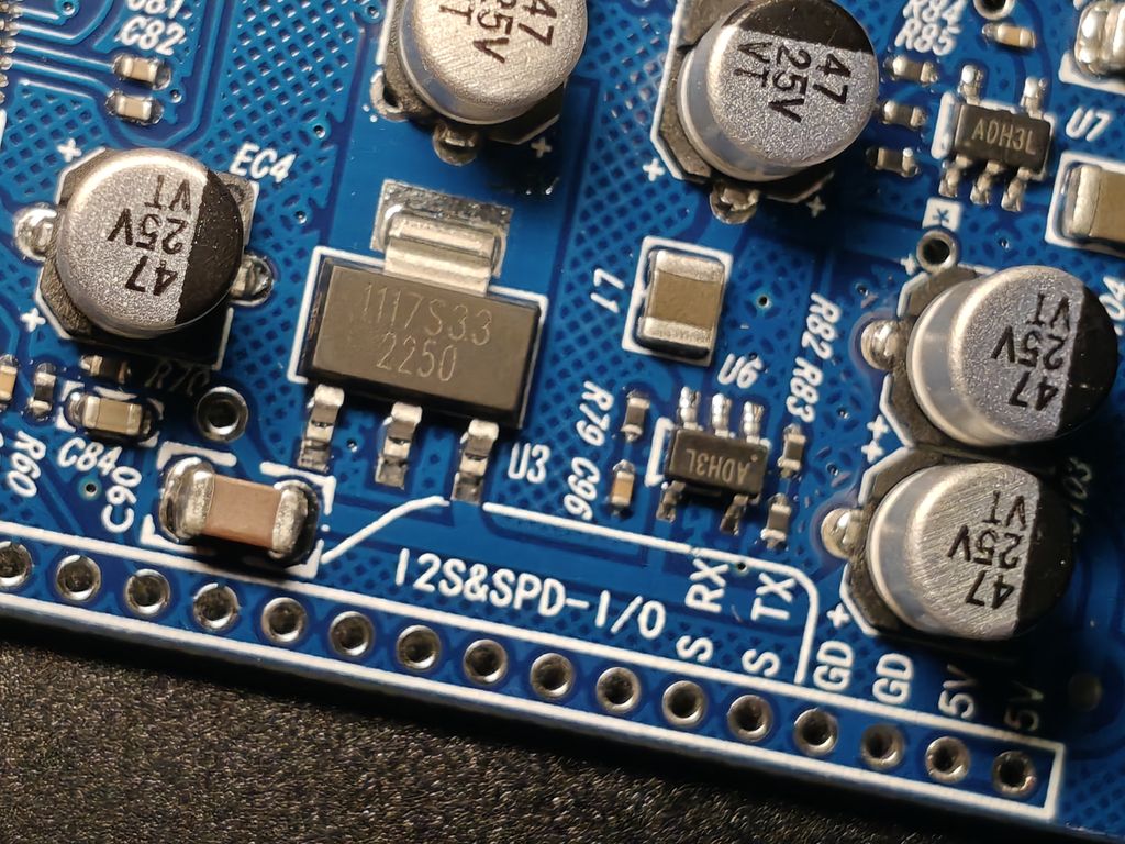
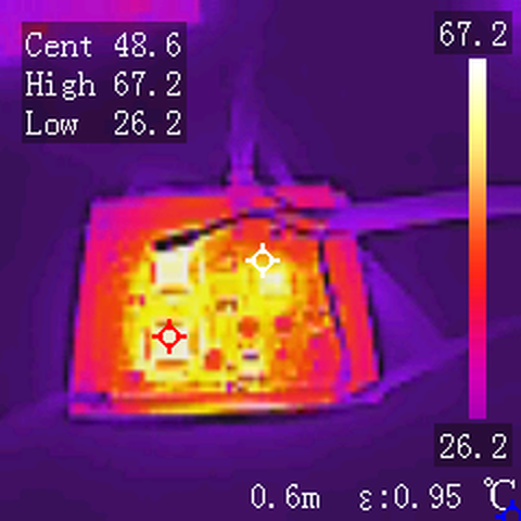
One other note is the chips run quite hot. You might want to buy some small heatsinks (like those RAM ones) to stick on to improve longevity. Grounding unused inputs might help with this. I've not tried though.
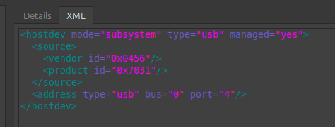
To program it, you’ll need SigmaStudio. Fortunately, it’s freely available from Analog Devices. It does need Microsoft Windows however, so to make it work on my desktop that runs a Linux OS I made a quick Tiny 11 VM using KVM / Virtual Machine Manager and passed through the USB programmer (USB 0456:7031) as a USB Host Device.
I brought my DSP from the "Deyin Professional Audio Store" and, after asking, I was given a google drive link which provides various information in Chinese and English for various DSP boards.
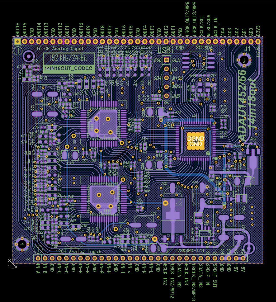
I could not find schematics for this one though (only PCB prints / layouts), see links below to see these for reference.
- ADAU1466-cs42448.avif
- 14in18out1466lines.png
- 14in18out1466parameters.png
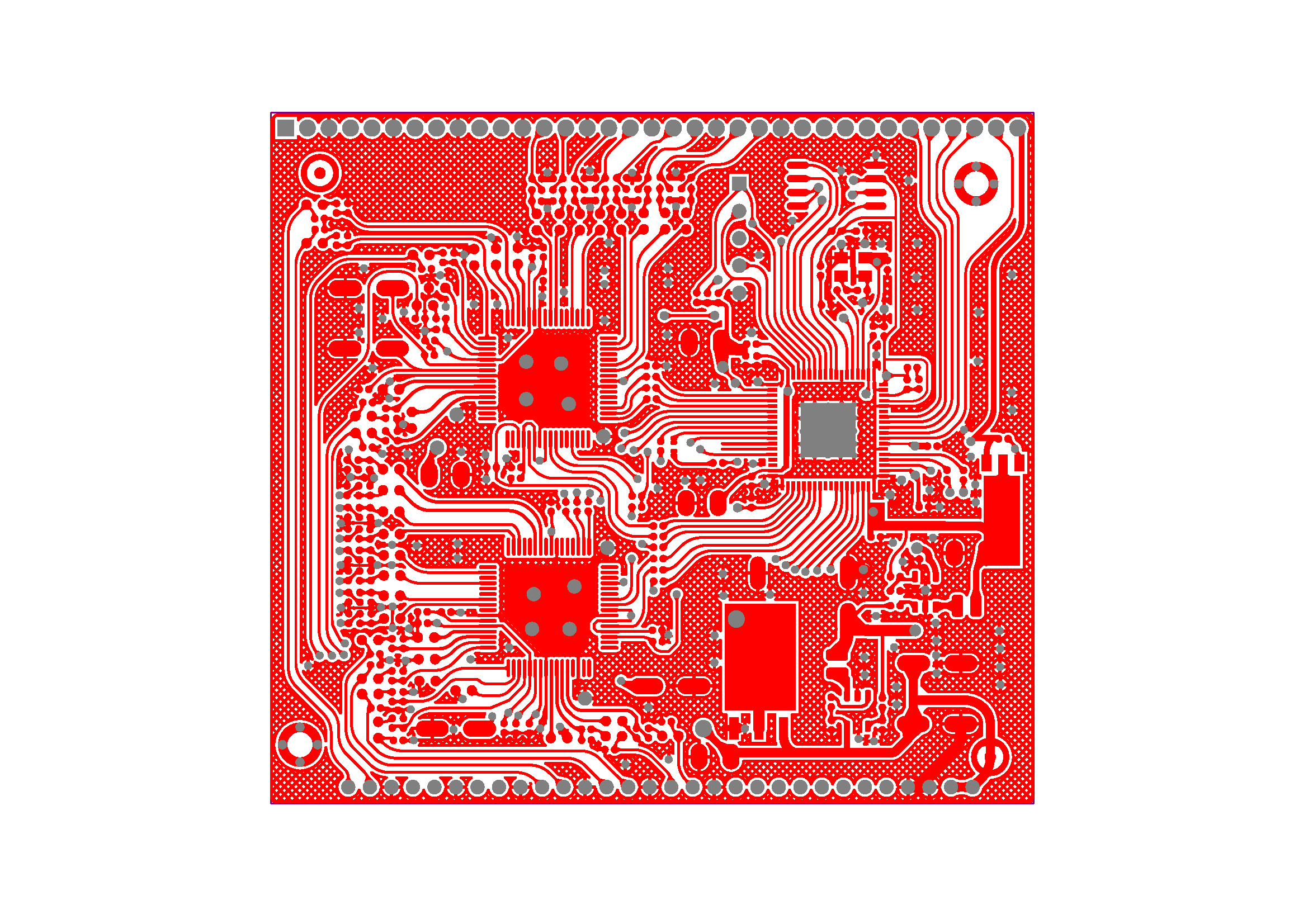
- 14in18out1466top.png
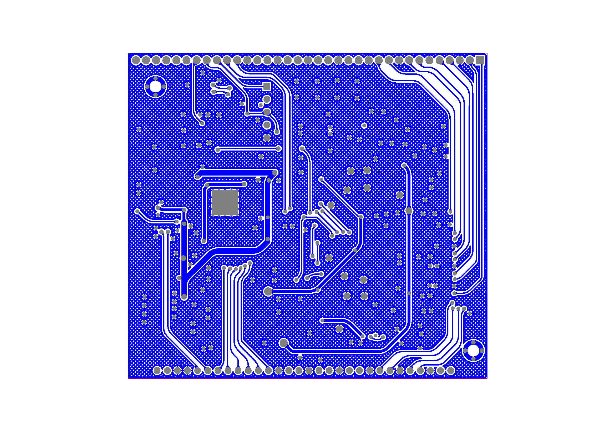
- 14in18out1466bottom.png
The useful SigmaStudio sample file for this board is 1466_cs42448_18out.dspproj. Click here for a quick English translated version.
The sample correctly labels the inputs A to L and analogue outputs 1 to 16. There's also digital inputs and outputs, but I have not tested these.
Simplified Sample
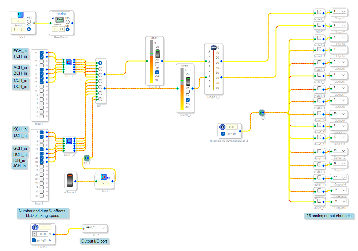
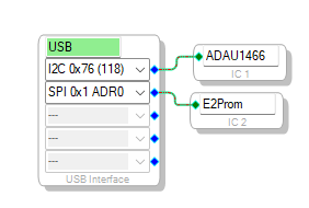
I’ve simplified the sample down to just the analogue inputs and outputs though, and a test tone / white noise with selectors. I also found I could not use default SPI for programming, but I found I could talk to it using I2C 0x76.
To hook up the programmer using I2C, only four wires are needed. Link SCL(1) to SCL, SDA(2) to SDA, GND(10) to GND and 5V(4) or VBUS to +5V pin (this is not on the USBi header). Unlike the ADAU1401/1701 boards, there is no separate header to short to enter programming mode. The board also has 10k pull up resistors on board for the I2C data and clock.
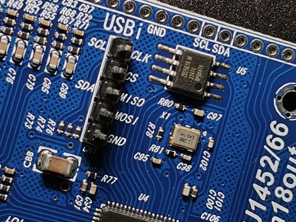
There’s a ZD25Q16 memory chip on the board too. It is not written to directly by the programmer as the DSP chip writes and reads from it via SPI itself.
To self boot your program (without USBi), you need to write to the flash through the DSP. To do this, ensure you've added the E2Prom in the Hardware Configuration with address SPI 0x 1 ADR0 as IC2.
Right click the DSP IC1, select "Self-boot Memory", then select "Write Latest Compilation Through DSP"
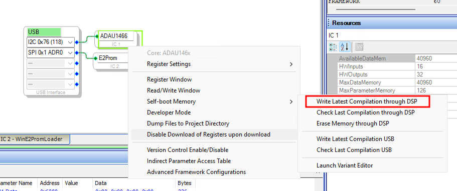
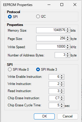
A popup will appear. The default settings seem to work fine.
Note that the "Check Latest Compilation Through DSP" does not seem to work, but if you now boot the ADAU1466 board without the USBi, it will start up with your program fine.
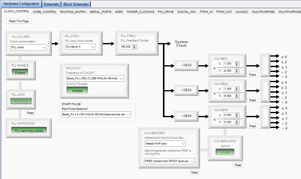
Update: My previous advice to set CLK GEN 1 higher is wrong and probably overclocking it which can lead to instability. The screenshots below and updated sample seem to get the best out of it within its limits.
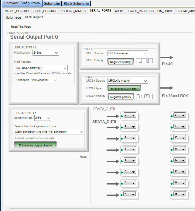
The sample file runs at 48kHz sample rate, but the DSP is capable of more. To change the sample rate, you need to update all the nodes but also change the hardware config, so CLK GEN 1 is N=1 / M=6 with the start pulse set to Base Fs × 4. The CS42448 seems to not handle 192kHz but runs at 96kHz ok (select Fs*2 for serial inputs 0 and 1 and serial outputs 0 and 1).
For my setup, my decoder is converting digital to analogue, so converting back to digital and analogue again before sending to the analogue amplifiers should be done at the highest rate as each conversion will lose accuracy of the original signal. Using 192kHz / 24-bit takes you into Hi-Res audio land and this means it will be hard to recognise and degrading of the original signal (which most of the time would have been sampled at 48kHz anyway).
You can download my simplified sample here.
SigmaStudio is available at Analog
For more research, there’s a great YouTube channel about Sigma DSPs - @HowtoSigmaDSP by David Thibodeau.
I'm at the beginning of my project for now, and life is busy, but as I explore more the SigmaDSP's capabilities and how to control it with an ESP32 or Pi Pico, I'll write further updates.