A frequency function generator using AD9833 and Raspberry Pi Pico
Now the owner of an oscilloscope for a few years, I often need to generate a frequency as an input to check the performance of amplifiers or other audio projects that I build.
An old smartphone with 3.5mm output is battery powered and does a good job with a tone generator Android app for generating sine waves. Generally, it does the job, but it's maximum output is limited, and I usually need an inline volume control to get a fine adjustment of the output voltage. Though I don't use them, the smart phone also cannot do triangle or square waves properly.
I decided to research methods to make a tone / frequency / function generator as a DIY project.
My requirements were that it should be quite small, not cost too much, and be able to push waves of 2V RMS or more.
There are quite a few others that have done it, but the best project I found was How to Build Your Own Function Generator Using Analog Devices’ AD9833 by Cezar Chirila at All About Circuits
Though there are pure analogue ways to make function generators, a digital way provides the best functionality and uses the less space.
Modules with the AD9833 are available on auction sites such as eBay, Amazon, AliExpress etc. and they are tiny! The chip uses a normal SPI bus to communicate, which is available on hardware in most microcontrollers as well as some SBCs.
Electronics
The AD9833 alone doesn't provide a strong output though and I'll need an amplifier to boost it to a higher level. The All About Circuits article covers that too, using an LM318N to boost the signal. It also provides a linear PSU for powering the digital and analogue components, and mine will be similar.
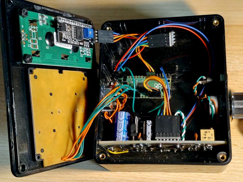
Providing input to the AD9833 is a Raspberry Pi Pico - a small microcontroller based on the RP2040. This is the edition without Wi-Fi, which makes it really cheap (for hobby builds).
An unused 16x2 character display (HD44780-like) with a PCF8574T based I2C adapter on the back will form the display.
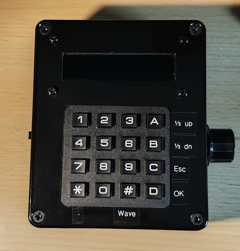
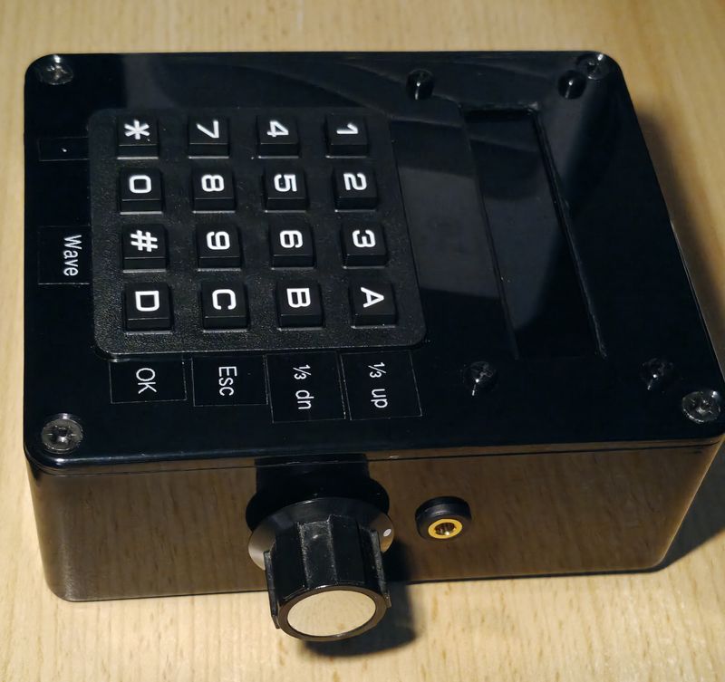
For input - I didn't like the idea of turning rotary encoders to get the frequency I want so I decided instead to buy a cheap 4x4 keypad. Just like the Android app, this would allow me to enter the exact frequency I want numerically, with the spare buttons used to 'OK' the new frequency, Cancel, add a decimal place, change the wave type (sine, triangle, square) and make ⅓ octave up/down jumps through the audible range.
The PSU would be a linear PSU made from existing parts I have, those being an external 12 V AC plug (this must be AC out, not DC), positive and negative 12V regulators, and a 5V regulator.
For the amplifier, to have a good slew rate for high frequencies, I went with a TLE2082 dual op-amp from Texas Instruments (found on eBay for £2).
The PSU schematic is below. It takes 12 V AC and uses a Full Wave Voltage Doubler (details at ESP link) to get the rectified DC required for the linear regulators. 2x 2,200µF capacitors smooth the ripple, and overall current draw is low, so a full wave voltage doubler works fine in this application.
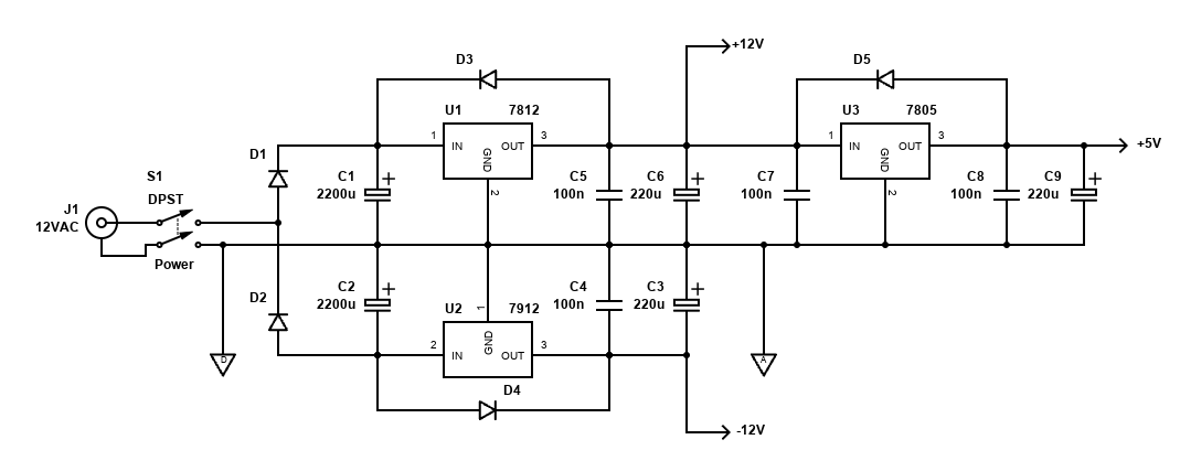
The positive 7812 gives +12V and the 7912 gives -12V for the op-amp TLE2082. Take care with the pinouts because the 79xx series regulators are different (i.e., pin 1 is ground, not pin 2). The 7805 provides 5V for the Pi Pico and the LCD.
Since the DC after rectifying is about 18V, the drop to 5V means 11V needs to be discarded as heat. Fortunately, the Pi Pico and LCD draws only 36mA, which is 0.18W at 5V. This means it will also draw 36mA at 18V, so some heat is generated in the regulators.
The heat is shared by making the 7805 follow the 7812. The 7812 will drop 18V to 12V (6V drop), so generates 0.22W of heat. The 7805 will drop a further 7V, generating 0.25W of heat. This allows both to share the load and small heatsinks is all that's needed.
The amplifier is per the All About Circuits article and as the TLE2082 is a dual op-amp, I separated the gain and offset sections. However, I didn't read and think too carefully and adjusting the gain like this affects the DC offset, which is quite inconvenient. As a result, I fixed the gain with an 18k resistor, adjusted the DC offset with the trimpot and followed the output with a standard potentiometer to ground, in a standard volume control format. It'll go noisy after time because of some DC involved in a function generator, but that's ok.
The output is from a stereo 3.5mm jack. This is because I'll most likely be testing audio amplifiers, often in stereo.
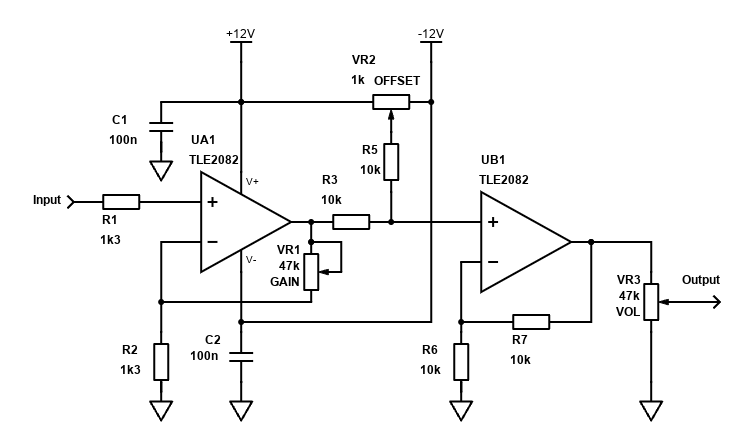
I did want to power the project from a standard DC power supply, but this becomes a challenge when dealing with the amplifier section. This is because op-amps require a dual power supply and whilst some charge pump or switching PSU modules can generate the -ve PSU, these are parts I don't own and I wanted to keep this project cheap for myself.
What about converting the amplifier to single supply using a virtual ground? I do this for a few audio circuits, but it requires AC coupling (a capacitor in series with the inputs/outputs) and whilst this would work fine for most sine waves (lower frequencies would have a roll off), for square waves it would not.
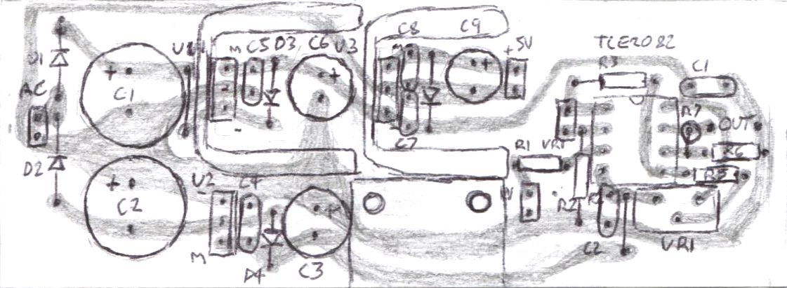
I made the PSU and amp sections on a PCB, with a little room for mounting the AD9833 module too. This was designed to fit nicely into the grooves of my ABS project box. Below is a scan of my layout (top view). Invert the image for a bottom view if drawing yourself. I made this using techniques in my PCB building guide. The layout was designed, drilled, drawn, etched and soldered within a day.
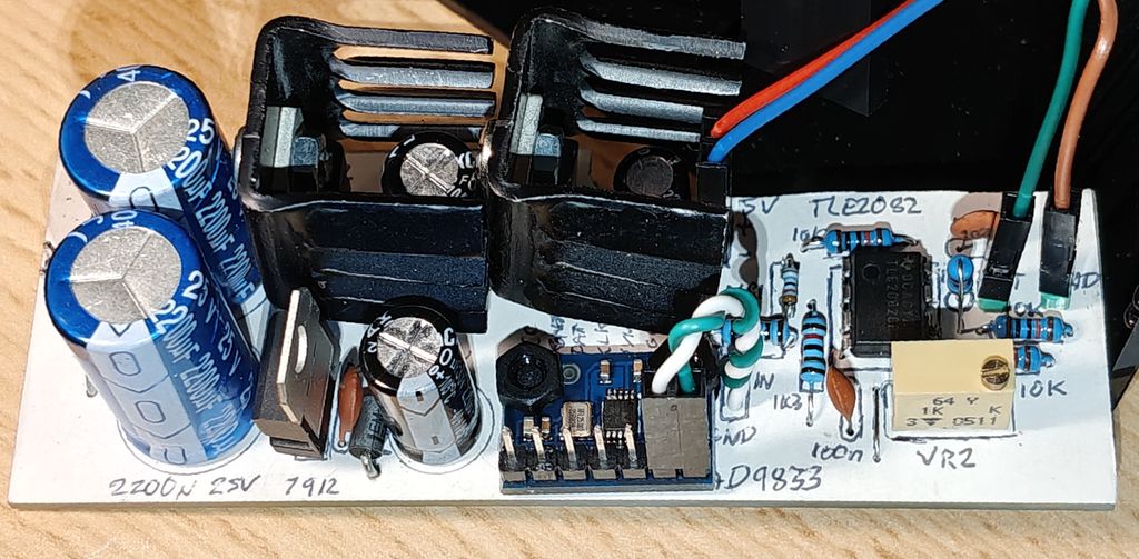
Here is a photo of the built PCB:
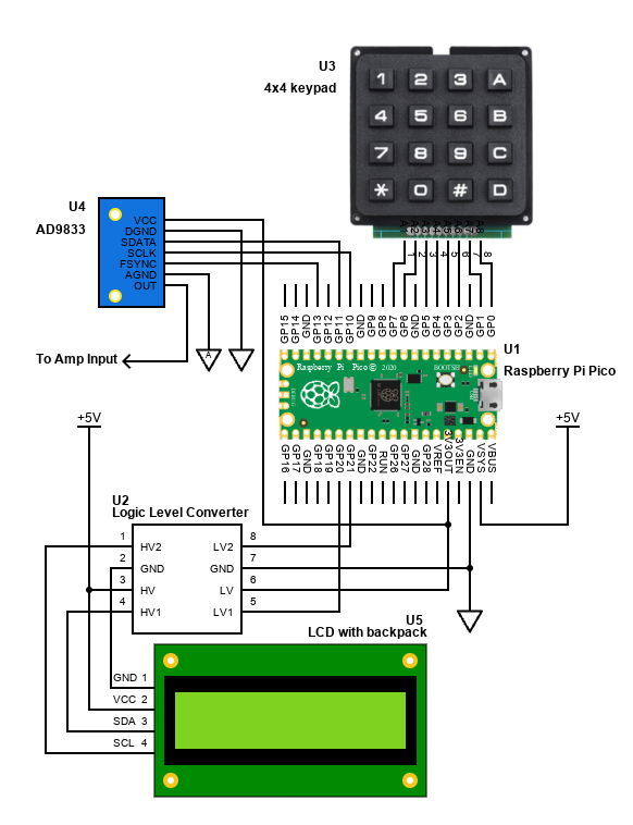
Finally, the diagram below shows how everything is connected. Since the LCD is designed for 5V operation I decided (rather than any other tricks / risks) to use a cheap logic level converter board to convert the I2C signals for safe and reliable operation. This could also be done with a couple of 2N7000 MOSFETs and resistors.
All of the components, except the external AC adaptor, fit inside an ABS project box - I think it's a Multicomp MB3 118x98x45mm. It's the usual shiny, easily scratched, fingerprint magnet, but it's cheap, easily drilled and filled to make the holes required. I should learn 3D printing one day though.
Code and operation
I wrote the code in MicroPython. The speed of C++ isn't needed here, and the available libraries made the code simple. It was only a few days' work.
The code is available on my github.com
Operation is easy. Switching on remembers the last frequency and wave type and activates the output within a second.
Changing the frequency is as easy as inputting the desired frequency via the keypad and pressing OK. There's a cancel in case of a mistake.
Alternatively, ⅓ octaves frequencies are programmed in and the up/down keys (A and B) jump to the next ⅓ octave.
The # button toggles the output from sine wave, to triangle, then square and back to sine again.
The only thing it lacks is a soft 'off'. I did try setting the frequency to 0, and whilst this stops any wave being generated, the output of the AD9833 isn't perfectly central and it floats somewhere between the maximum or minimum voltage. Since it starts up quickly, I'll use the power switch to turn on/off. Alternatively, a switch to short the output to ground would work too.
Conclusion
The monetary cost of this project was very small. I already had the box, Pi Pico, LCD and almost all the components and only had to buy the keypad, op-amp and logic level converters - so that's just over £10 recent cost. Of course, if you were buying everything it would be a fair bit more but still possible for under £50, especially if prepared to wait for a few things to come from China.
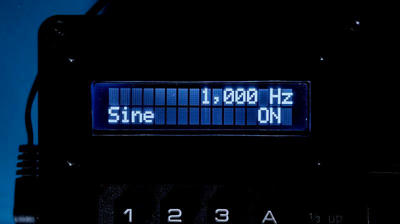
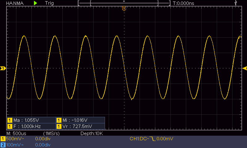
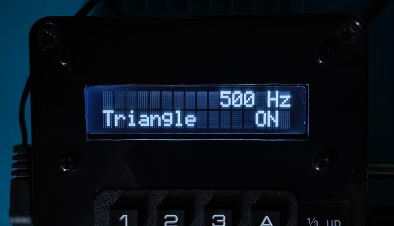
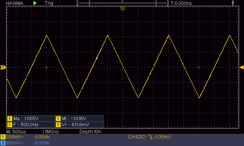
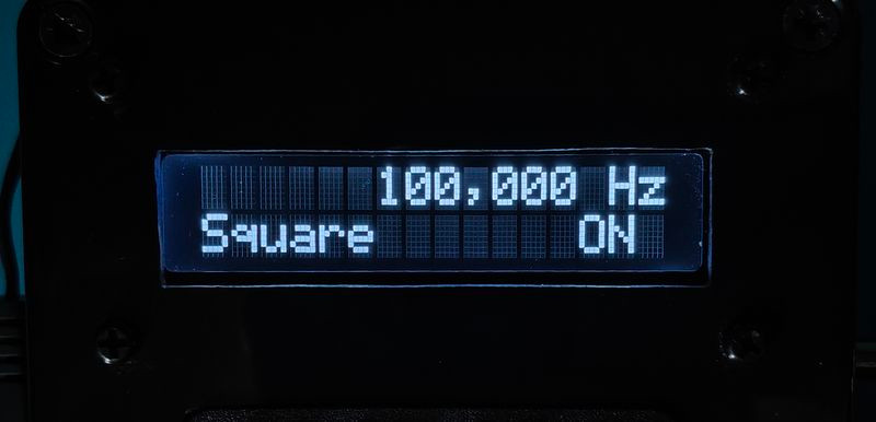
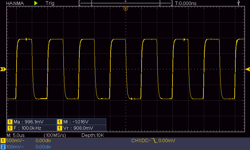
It works well, and below are samples of different wave types at different frequencies. As I post these, I realise I could have done a little better with the DC offset adjustment as max voltage is more than the min. Adjusting the 10k trimpot would fix it.
Here is a picture of the side, showing the volume control and the 3.5mm output socket.
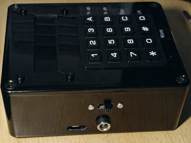
This is the other side, showing the AC input socket, power (slide) switch and there is also a hole for the Pi Pico's USB port (this saved time whilst programming and testing, but now it's a bit useless).
