
Nobo Heating Electric Radiators Battery Repair
I've been in my flat since it was built in 2009. There's no gas, so our water and air heating are all electric only.
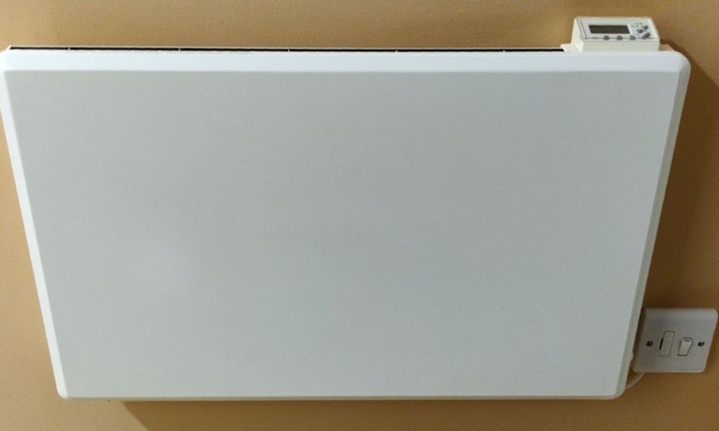
The place came with four of these Nobo (Nobø) heaters / radiators of various sizes and they heat the room fairly well. Models include Nobo E4EU203-152A1X, E4EU103-077A1X and E4EU 073-062A1X for 2kW, 1kW and 750W sizes.
A while back we just hit a cold spell of below zero temperatures even in London, I found out I've now got a third heater dead out of the four, and this one is the largest one used in the living room / kitchen.
Replacement is somewhat costly, and then you've got to get the broken one to the recycling centre after as well as drill new holes in the wall, fill old ones and paint. Repair is even more costly assuming you can find replacement boards. So, I checked if I could DIY repair.
If the battery runs flat, switching on the heater for a while (perhaps 24h) might be enough to revive it and charge back up. This can happen because in the UK (south east anyway) as we typically don't need any heating 6 months in the year, so the heater gets switched off at the wall spur permanently to reduce idle power consumption.
Unfortunately, unless you maintain them, these batteries don't last forever and either get discharged too much or overcharged.
Symptoms of a dead battery were different per heater. One did nothing at all, another would just switch on, with a flicker of the red LED, and another could be switched on, but it was in permanent heating mode - completely ignoring the timer and thermostat temperature.
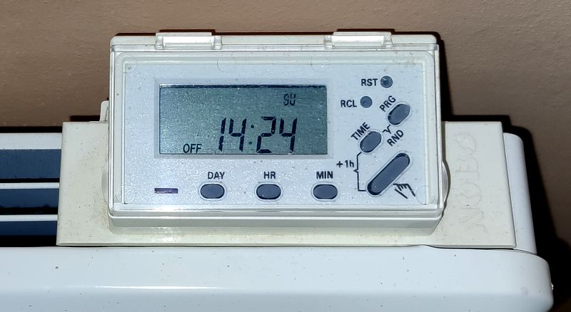
The timers on top also had problems. Two were off and displayed nothing, and a third doesn't display the time either (only programs) and turning the thermostat setting and pressing the main button to activate heating on demand does nothing.
I decided to dismantle and see if they could be repaired. I had one working heater left which thankfully I could use to understand the circuit and reverse engineer it.
They've all got the same electronics / PCBs in them.
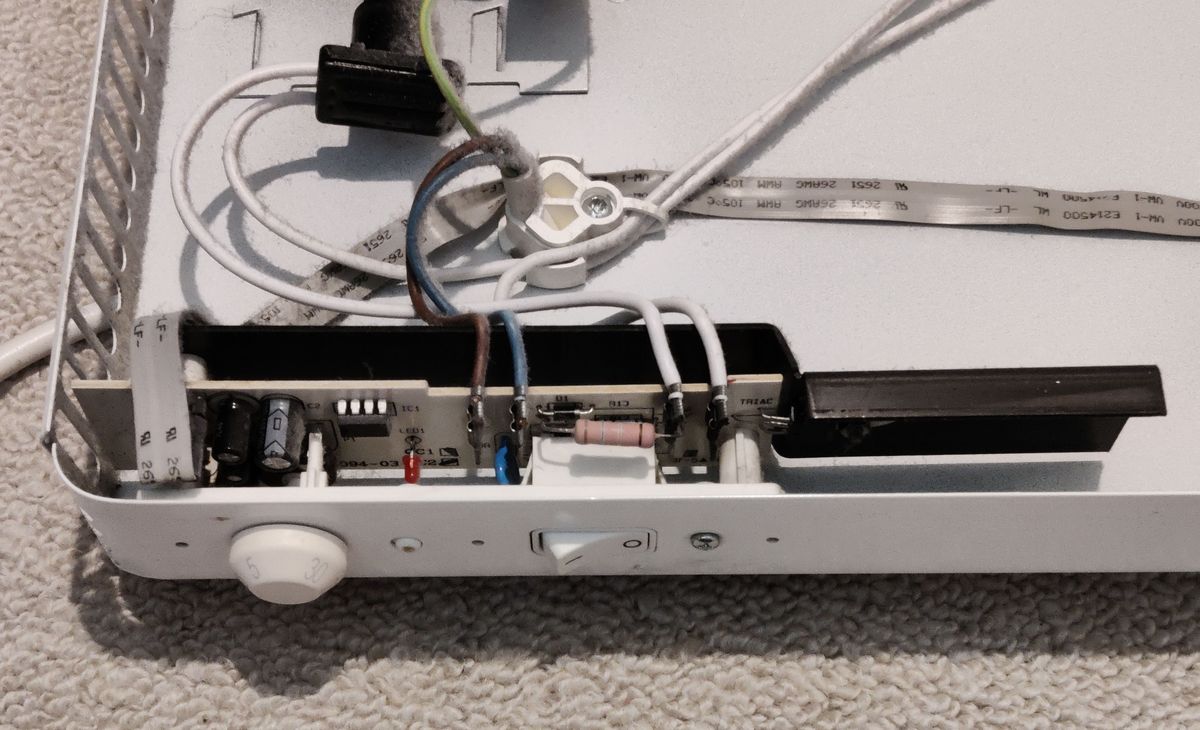
The main circuit (a.k.a. regulator unit) is in the side near the thermostat and main power switch.
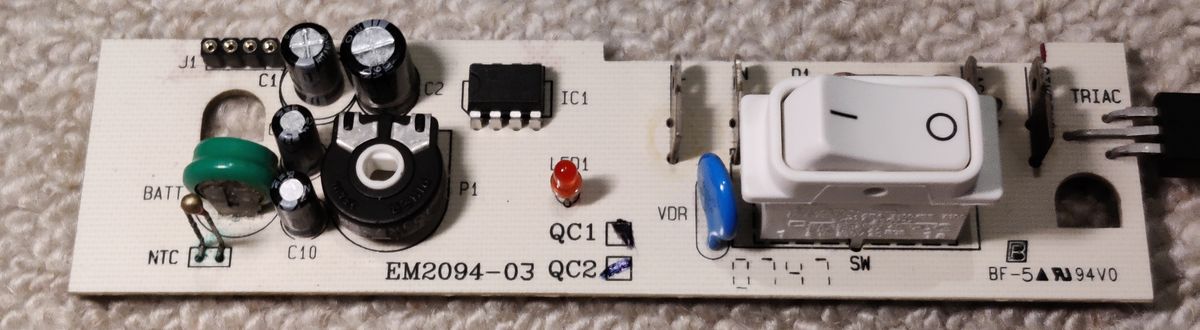
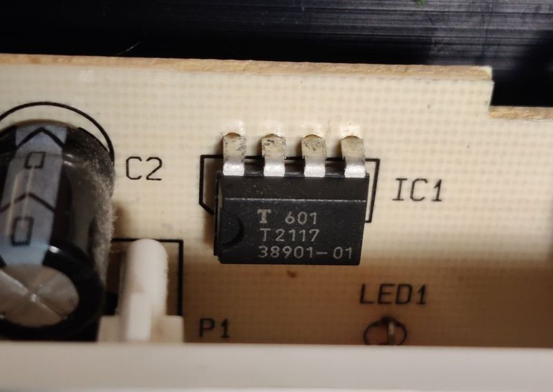
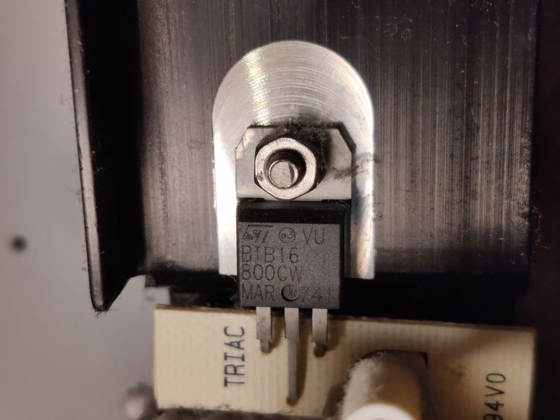
The basic function of the temperature controlled heater is by the T2117 DIP IC by Atmel. This is a Zero-voltage Switch that triggers a snubberless TRIAC (BTB16-800CW by ST) based on the resistance of an NTC thermistor.
As the chip produces a reference voltage, this can also be used to charge the battery and power the timer. It does this directly from the mains, so there's no transformer.
Additionally, the regulator unit board has a rechargeable battery and a bunch of surface mount NPN transistors (BC847C) and switching diodes (BAV70) with accompanying resistors sit on the solder side of the control board to interface the timer board and battery charging.
On top is a chip-on-board microcontroller and LCD with buttons is in the top - but in most cases you don't need to access that.
This timer that can enable or disable the heating based on programs or override. The programs and LCD clock are kept running by a rechargeable battery - and that's the reason for problems.
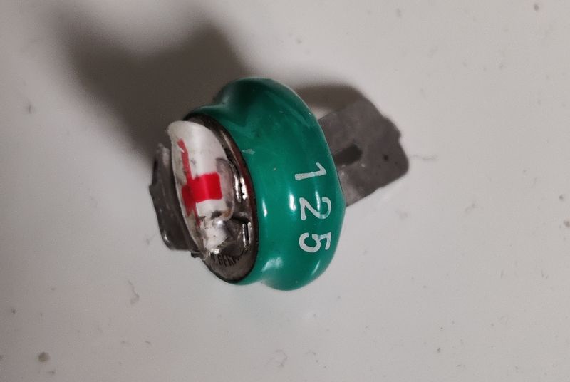
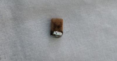
The battery in my sole working heater gives off 1.358V when there is no power. The only marking is 125, but a standard Ni-MH 1.2V 40mAh rechargeable battery with solder tags (spaced about 5.5mm apart) seems to be a suitable. A reader with the same problem found the batteries made by "vhbw" in Germany.
Make sure you are getting a battery of the same size as the large 80mAh alternative won't fit (due to height/diameter). Diameter should be around 11.7mm, total height no more than 16mm (including tags).
However, it's not easy! It may be difficult too, as was the case for all of my heaters that stopped working.
Before I say anything more - opening this heater exposes DANGEROUS MAINS VOLTAGES.
NEVER power it from the mains whilst open. This is particularly true of transformer-less appliances such as this as probing even the low voltage areas of the circuit is dangerous. The Traic is also not isolated so even its heatsink is live.
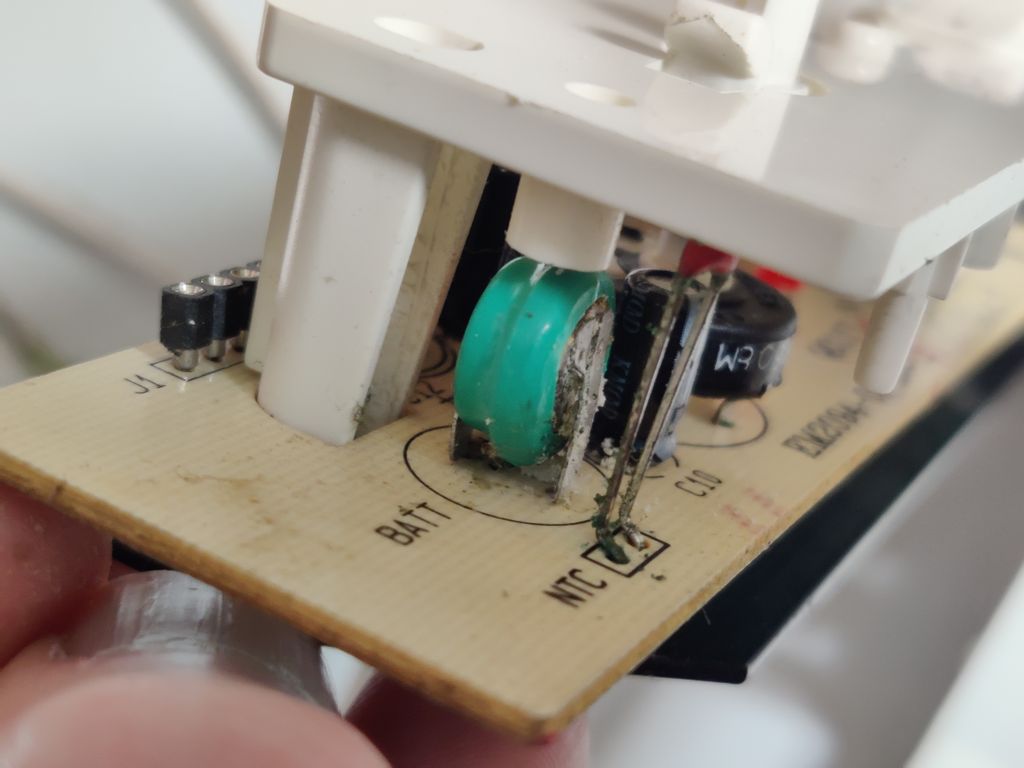
Secondly, the battery is soldered so you need a soldering iron. Between the terminals is a surface mount capacitor C8 which you'll probably destroy too whilst de-soldering, or it may already be destroyed by battery acid. So, I suggest to get replacement capacitors too. A 10nF ceramic capacitor will work and you can either re-solder a surface mount in place (size 0805), or alternatively solder a through hole one 10nF on the back, keeping the leads as short as possible.
Finally, there's a high chance that the battery has leaked and took out some of the circuit board in the process.
This happened to all my heaters. The acid leakage was severe enough to eat some of the PCB traces to the point where they were no longer conductive.
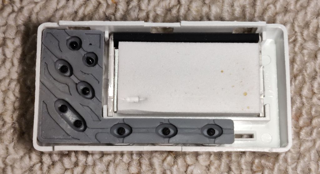
Opening the heater is easy enough. There are two or three screws on the bottom which can be opened with a normal pozidriv screwdriver and the front levers off. Have a duster / vacuum cleaner handy as you'll have an opportunity to clean off probably years of dust meanwhile!
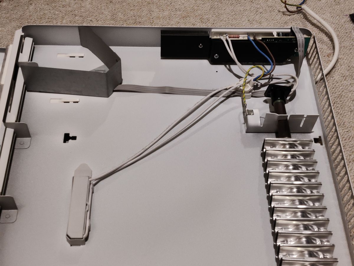
You can leave the timer LCD in place in most cases, this is tricky to open, and you'll likely break the plastic (I did). Just remove the four pin cable to it, remembering its orientation.
To remove the regulator unit circuit board, remove knob for the thermostat (pull straight - don't wiggle it). If your heaters are like mine you may see a screw just beneath the switch which can be unscrewed with a smaller screwdriver. It then levers out.
Another reader kindly reported that instead of a screw, a white peg is there instead. The inner end this peg has a head with a flat underside so cannot be forced out without splaying the holder. Use something like a large screwdriver to put in the gap and turn through 90 degrees with another small screwdriver to free on side of the peg from the holder can help remove it. To reassemble after the repair, push the splayed ends back together and it should lock back in place securely.
You can then unscrew the heatsink off the back of the board which can be gently tilted back for assessment. Be gentle and don't tilt too far otherwise the legs of the triac will break off. For easier repair, it is better to unscrew the heatsink from the traic too - you'll just need to clean off the existing page and reapply fresh non-conductive thermal paste once the repair is done.
Once the heatsink is fully removed, you can then remove the plastic cradle too but be aware that there is a snap-in peg next to the battery you'll need to squeeze first to remove.
Once you can see the traces, you can assess the situation. With luck, it's all ok. Clean up with isopropyl alcohol (isopropanol / IPA) if required. Then desolder the old battery.
Since its lead-free solder, the easiest way to desolder is to add rosin core leaded solder which mixes and provides better heat transfer into the lead-free solder, then you can heat again and mop up the solder with desoldering braid.
If unlucky, the battery acid did damage and you'll need to clean up and re-create parts of the circuit.
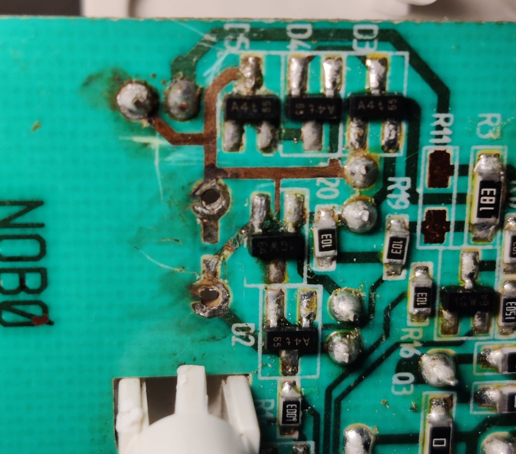
This happened to the capacitor due to acid damage, so that also has to be replaced:
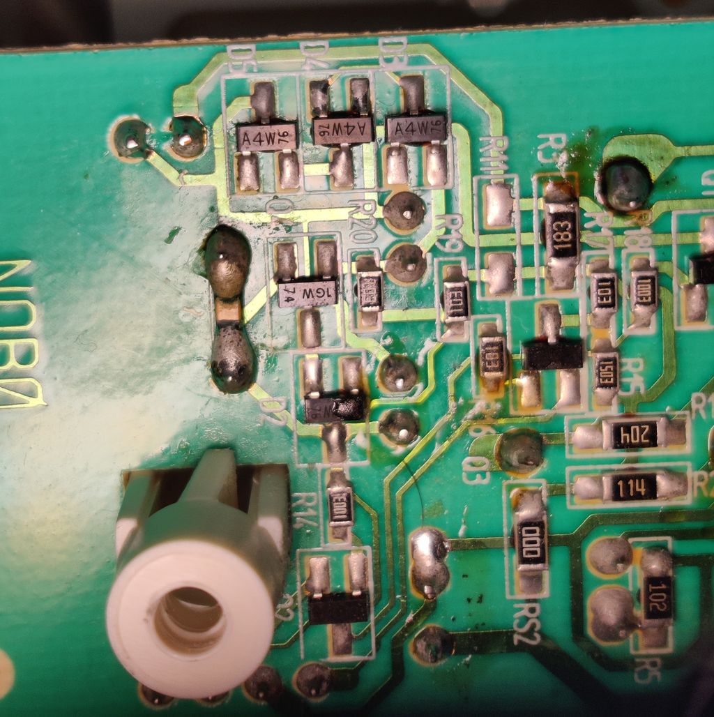
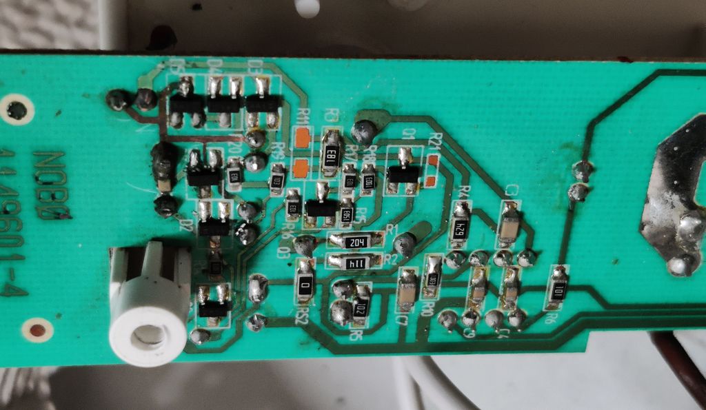
Below are pictures of my three successful attempts to use component lead offcuts and wires to recreate the approximate path of the PCB traces affected by acid. It's not pretty, but it works. Use wire with 105°C insulation.
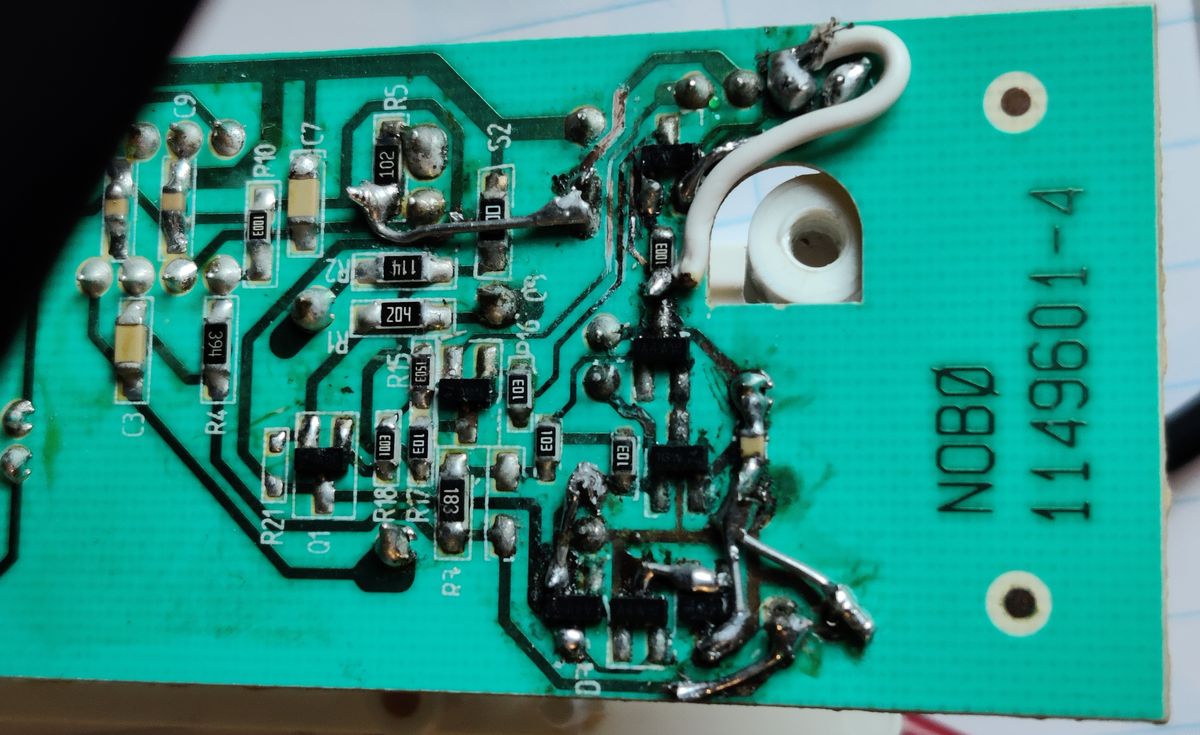
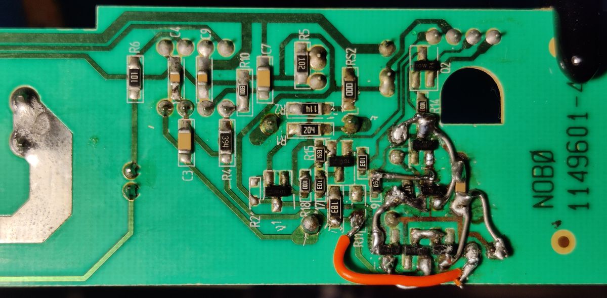
The damage to all was quite surprising and two were particularly bad - needing many traces replaced. Still, only traces needed repairing and the battery and capacitor across it were the only two components that needed replacing.
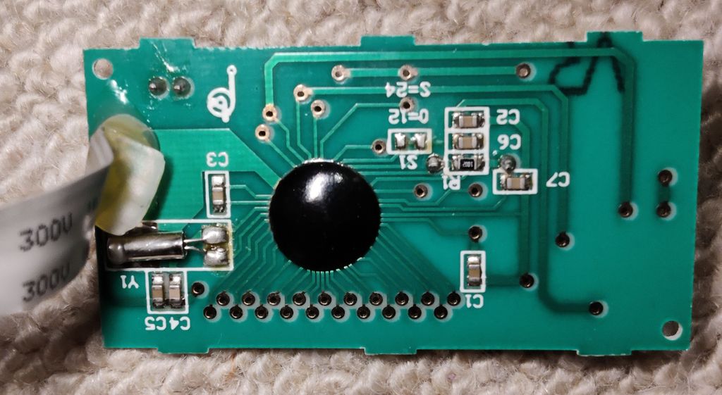
To help recreate the circuit, below is a reverse engineer of all the traces, and a schematic. Most of the issues will be with traces close to the battery, but on one board even traces close to the timer header and Q2 had damage too.
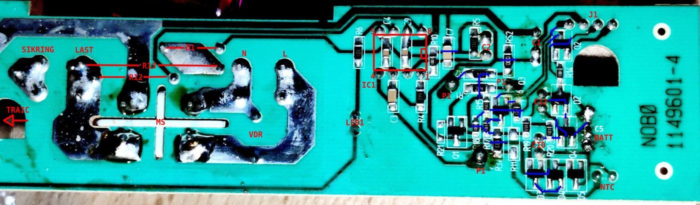
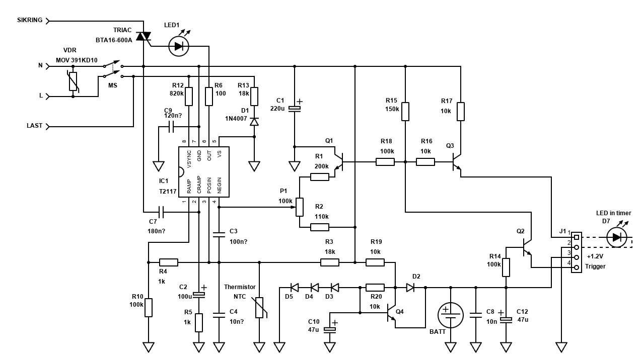
Note: Capacitors C3, C4 and C7 are a measured in-circuit - shouldn't be too far off but it's possible the IC or other components affected my reading.
Timer problems
After repairing the regulator unit boards for three heaters - two were now fully working again. One could still not be activated.
Swapping the timer from another working heater confirmed that the regulator board repair was fine, so there had to be a fault with the timer too.
To attempt to repair this - I had to disconnect the timer. The timer unit is attached with only one small screw inside the heater, and two plastic latching tabs.
After detaching the four pin timer cable from the regulator board, you can thread that through the holes and completely remove the timer from the heater.
Now you need to detach the module from the cradle. This was tricky and I did not manage it without breaking two of three plastic tabs. It's old plastic, right? That's what I told myself anyway...
Then you can remove the PCB from the front cover by bending the side forward so the protruding parts of the PCB exit.
Clean the buttons and contact area with isopropyl alcohol, but that might not be enough so order a button repair kit to re-apply the conductive layer.
If the LCD isn't working or is missing segment, also clean that zebra connector.
Unfortunately for my timer, cleaning the buttons did not help and even when I manually shorted the pads on the board, there was no response. As these pads go straight to the chip there is nothing more that can be done.
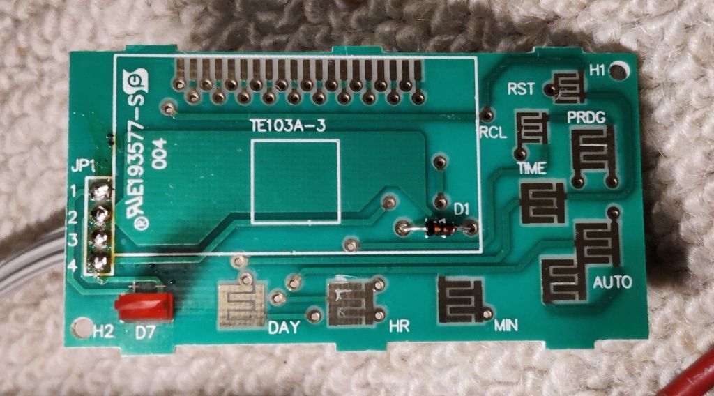
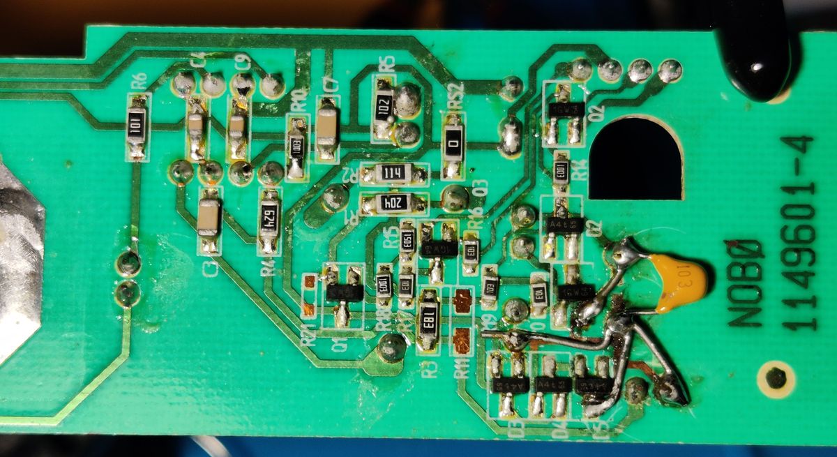
So, if the timer is beyond repair or you don't want to use the timer at all, you could just bridge pins 3 and 4 of the header on the regulator unit board. See below - the orange line indicates what to bridge (top right).
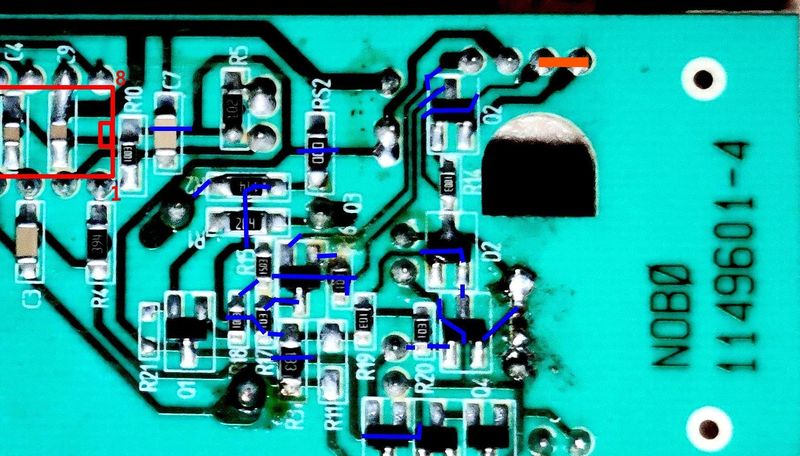
If bridged like this - the heating would be on when you manually switch the master switch at the side and per the thermostat setting. In this configuration, the 1.2V battery is not required, so remove it. You get the added benefit of knowing that in future battery leakage isn't going to part destroy the regulator board.
There is potential to convert these to "smart" heaters by replacing the timer with a Raspberry Pi Pico or something similar - just keep it isolated via a relay or opto-coupler and power the Pi separately to stay safe!
Part 2 shows a solution using the Pi Pico as a web interface to activate and control the heating, all from the convenience of your desktop or Smartphone.
If the repair is too complicated, there is also an option to have the heater in a permanent on or off mode. This can be done by bridging pins 1 and 2 of the Triac (A1 to A2). In this set up, the master switch will still switch on/off the heater, but there will be no timer or temperature control at all and leaving it on accidentally would leave you a hefty electric bill!