
Shared 12V to 12V and 5V Output PSU for Power Amp and Bluetooth with Protection
With more and more phones (sadly!) coming without a 3.5mm headphone line out, connecting your earphones or amplifier to your phone without wires is a common modern day convenience we're getting used to.
There are many pre-built amplifier + Bluetooth modules that have the necessary electronics and ground layouts to work effectively, but what if you want to build your own amp or add Bluetooth to an existing system?
Plenty of Bluetooth audio modules are available on auction sites such as AliExpress, Ebay, Amazon and the like. They are very cheap for what they are and if you have an Android phone at least, they work well (although some might be vocal about their status in poor English).
They can be powered from a 5V power source, and they'll only need around 20mA average when working.
The challenge is, unless you are very good with the grounding layout, using the same power supply to supply both the Bluetooth module and the amplifier becomes a challenge, and one that would probably involve changing the existing amplifier design and grounding scheme. The telling symptom of bad grounding is a varying high-pitched whine/noise that can be heard through the speaker when the module is powered on. It might be less noticeable when music is playing, but in-between tracks or music paused, it's clearly unacceptable.
You might be able to cure noise just enough by star grounding and using only one ground wire to the Bluetooth module and have this connect to a single point (either the PSU or the amplifier input) and ensure the amplifier signal ground and PSU ground connects to the same point. This may not be effective enough on its own though, especially if you have multiple sources and different ground layouts.
Another way could be to use small signal 1:1 transformers to isolate the L/R audio out from the Bluetooth module to the input of the amplifier. This can help cure the noise, but the transformers do take up some room and unless you buy very high quality audio isolation transformers, you might be unhappy with the degradation of the audio signal cheap ones cause.
The way presented here is to make the Bluetooth module 'appear' to be powered from a separate PSU by using an isolated DC-DC convertor.
For low powers, these isolated DC-DC convertors are fairly cheap, and they can also do voltage conversion at the same time.
In my case, the amplifier and the rest of the electronics is powered from 12V, so I used a DC-DC convertor with a 12V nominal input that supplies a 5V output. Specifically, I used the Traco Power TBA 1-1211 having being the best balance between price and performance for my STA540 amp when I brought several of them at the time.
This can only provide 1W of power output (that's 200mA at 5V), but this is more than enough to power the Bluetooth module. As it's a switching power supply, it will also do it efficiently - give or take 80% typically. Compared to a linear regulator like a 7805 which would burn [12-5]*0.02 = 140mW as heat, an efficiency of just 41%.
If your PSU isn't 12V, there are many different models for different voltages, such as 5V to 5V, 24V to 5V and even ones that can step up e.g., 3.3V to 5V.
There generally aren't any options with a variable DC input though, and also nothing between 12V and 24V so if you have an input voltage of say 19V, then you can knock the voltage down to 12V with a 7812 linear regulator. At 12V, the current in will be ~10mA, so the 7V difference producing 70mW of heat is reasonable unless battery powered. You can use a normal switching regulator like LM2596 or 7812 compatible switching DC-DC convertor if the efficiency matters to take any input and produce 12V output or go all the way to 5V with the standard DC-DC convertor and use a 5V to 5V isolated DC-DC convertor after.
Assuming a 12V input though, the schematic below shows components that should be precede and follow the DC-DC convertor for both protection and additional filtering.
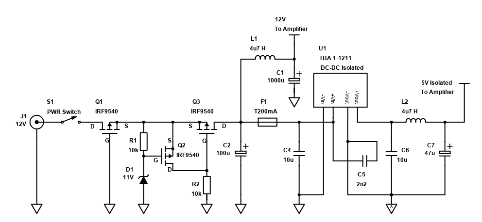
Although not too expensive, the isolated DC-DC convertor isn't super cheap and doesn't protect itself from over-voltage or reverse polarity. P-Channel MOSFETS Q1, Q2 and Q3 along with Zener diode D1 and resistors R1/R2 form a protection circuit which has reverse polarity protection (handled solely by the backwards connected Q1) and over-voltage protection (Q2 will switch off Q3 once the voltage is ~1..5V above the Zener D1 voltage under testing).
The 11V Zener diode is based on my own testing with the IRF9540 MOSFETs I had. I found the over-voltage protection started to work around 1.7V above the Zener voltage (I expected it to be around 2V), meaning the power was cut once the input voltage exceeded 12.7V. With a 12V Zener, the power cut happened at 13.44V (just under 1.5V difference).
With the 12V Zener, that cut off is a little above the threshold supported by the DC-DC convertor, so I used an 11V Zener in the final build, giving a cut off at 12.7V. Different MOSFETs will have a different performance though so you'll need to measure (as VGS(th) varies).
A 12.7V cut off means only a regulated PSU can be used. Non-regulated will likely trigger the over-voltage protection.
If you want more flexibility and can use a higher input voltage for your amplifier, I'd actually suggest using a 7812 (or switching alternative) or equivalent 12V LDO before the Isolated DC-DC, or consider a 5V to 5V Isolated DC-DC and a switching compatible 7805 (such as RS Pro K78xx-500R3) as this will take an input voltage range of 15-36V for the 12V one, or 6.5-36V for the 5V one .
The MOSFET protection circuit above is also limited to a maximum of 20V, so if your user can connect a PSU with a voltage beyond this, it won't add complete protection. Most PSUs with a common 2.1mm or 2.5mm DC jack do not output voltages beyond this though. This limit is from the Gate-source voltage maximum rating of ±20V of the IRF9540 and many other MOSFETs.
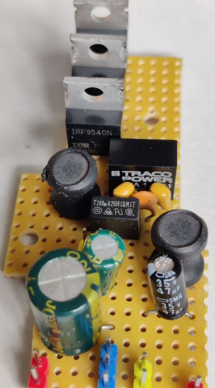
The IRF9540 (IRF9540N) was picked as it's what I had in stock. It's overkill, especially for Q2, but since smaller through-hole P-Channel MOSFETs in a TO92 case are not common at all (the common 2N7000 is N-Channel), I suggest you get a bunch of the same ones or similar TO-220 P-Channel MOSFETs as they are useful. Be aware of different Source, Gate, Drain pins though if you get different components.
C2 provides some basic PSU smoothing for both power supply paths. L1 with C1 provides a low pass filter and further PSU smoothing for the amplifier to be connected to. This well help reduce any noise from the input side of the isolated PSU, as well as filter any noise from the mains DC power supply connected to J1. You may not need L1, but it's advisable.
F1 is a slow blow fuse in a Radial package that can be soldered to the PCB (I used RS PRO Non-Resettable Wire Ended Fuse, Radial 200mA, 250V). Again, you can skip this, it's just for extra protection of the DC-DC convertor should the load pull more than 200mA.
Before and after the DC-DC convertor, you should put low ESR capacitors as close to it as possible. I used some 10uF MLCC. In combination with C2 and C7 which can be standard electrolytic capacitors, this seems to provide the stability required. L2 is also optional, but this provides some PSU noise filtering before passing the 5V output to the Bluetooth module. The 2.2nF C5 between the +Vin and -Vout should be a ceramic capacitor and it provides a lower impedance return path for noise (following advice published by Recom Power).
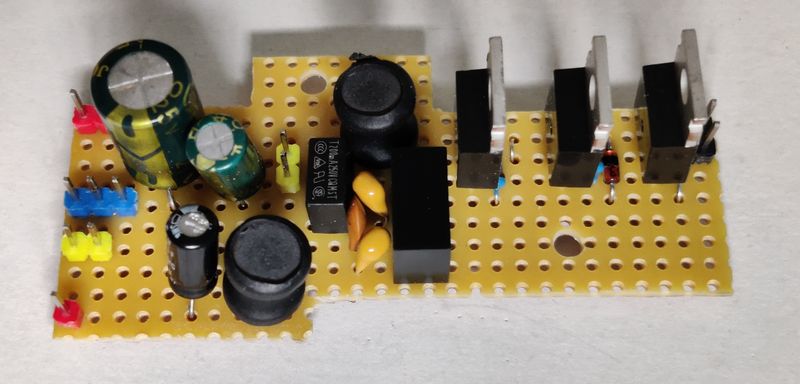
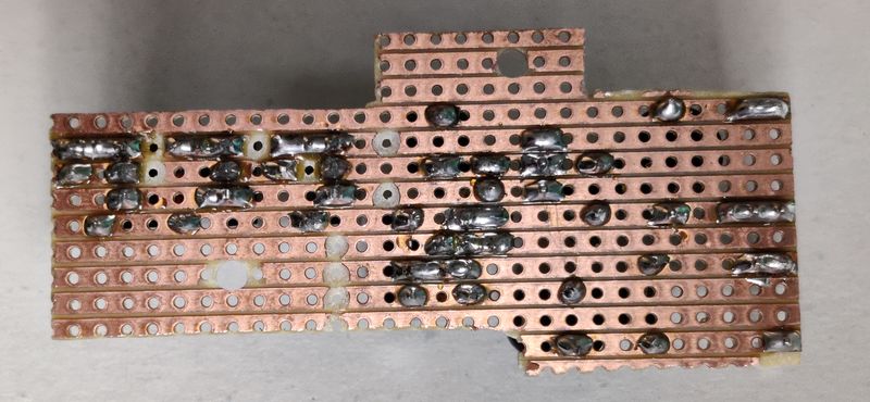
That's all there is to it. These components fit standard 0.1 inch / 2.54mm spacing so it was fairly easy to design a Stripboard layout with only a few track cuts and jumpers required. Soldering the Stripboard took a little over half an hour and apart from forgetting to solder one leg of my DC-DC convertor (you can spot this in the underside picture below!), it works well with no noise.
Here is a diagram of the Stripboard layout:
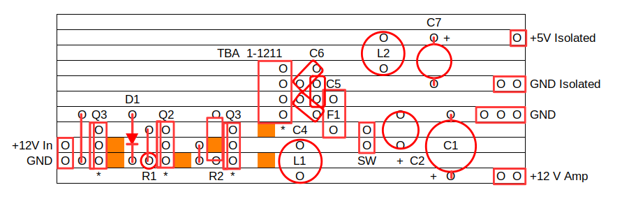
Note that the jumper labelled SW is for a switch that would allow you to switch the power to the Bluetooth module on/off separately, e.g., in cases where the amplifier has switched inputs and may support other sources.
Some further pictures below. The weird PCB shape is because it is offcuts from other projects, and somewhat messy soldering is because it's a quick late night build, without flux or cleaning the board first! Quick and dirty - but I'm confident it will work for years!
EE StackExchange Answer - Zener + MOSFET overvoltage protection
Recom Power - Very low noise filter for isolated DC/DC converters
Traco Power TBA 1 Series Datasheet