
TDA1514/TDA2040 Surround Sound Amplifier - Mark 3 - Surround Sound Amplifier 2020 Remake
1 - Ideas and Design, 2 - PCBs, 3 - Amps, PSU and Grounding, 4 - Digital Control and Software, 5 - Results and Pictures
Part 5 - Results and Pictures
On this page...
Gutting the previous build
Originally I was only going to change the preamp and add digital control to the existing amplifier, but after tearing it down and feeling a bit displeased with the state of it, I decided that the improvements would go much further!
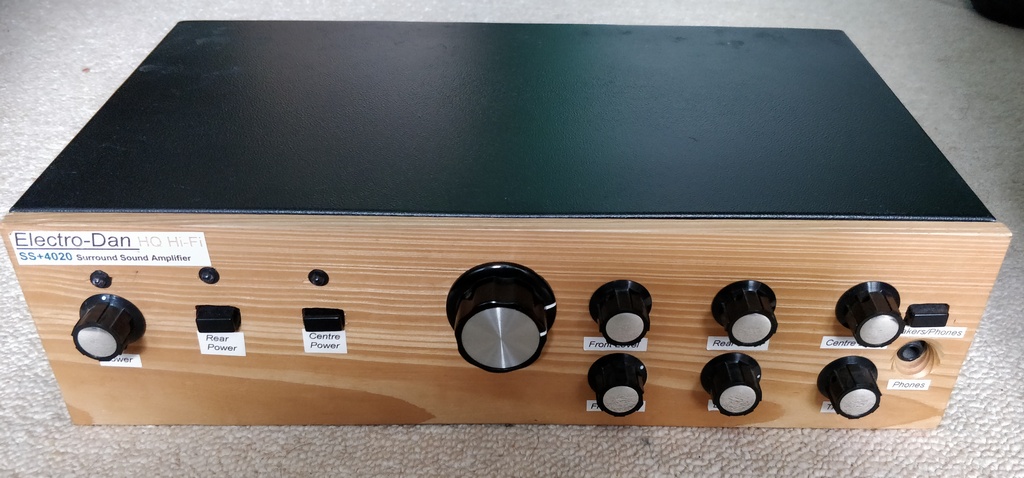
Above: Last picture of the amplifier before its teardown!
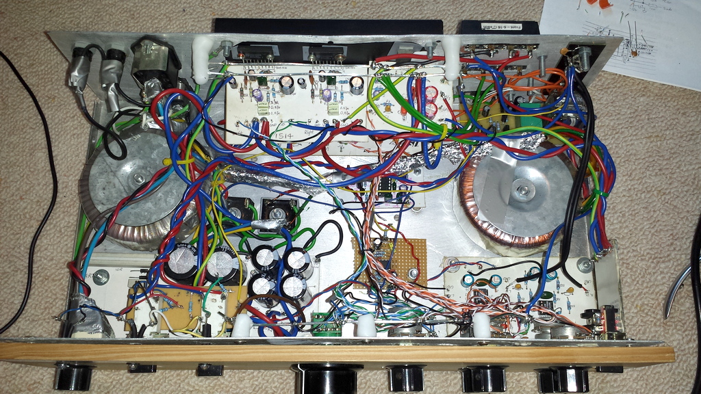
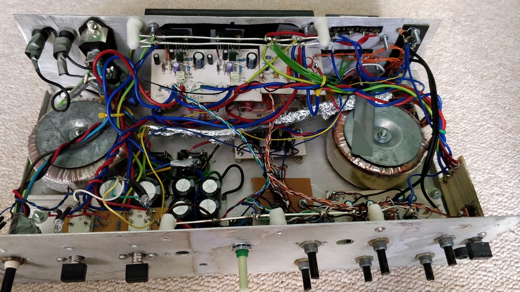
Above: Inside picture of the amplifier before its teardown
Above: Front panel removed
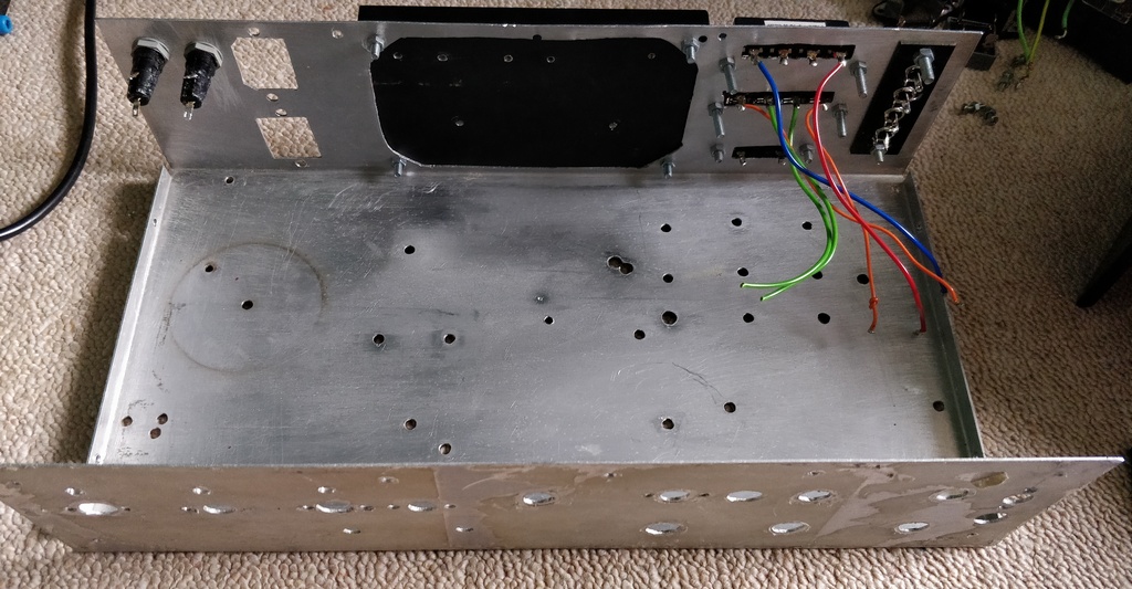
Above: Completely empty
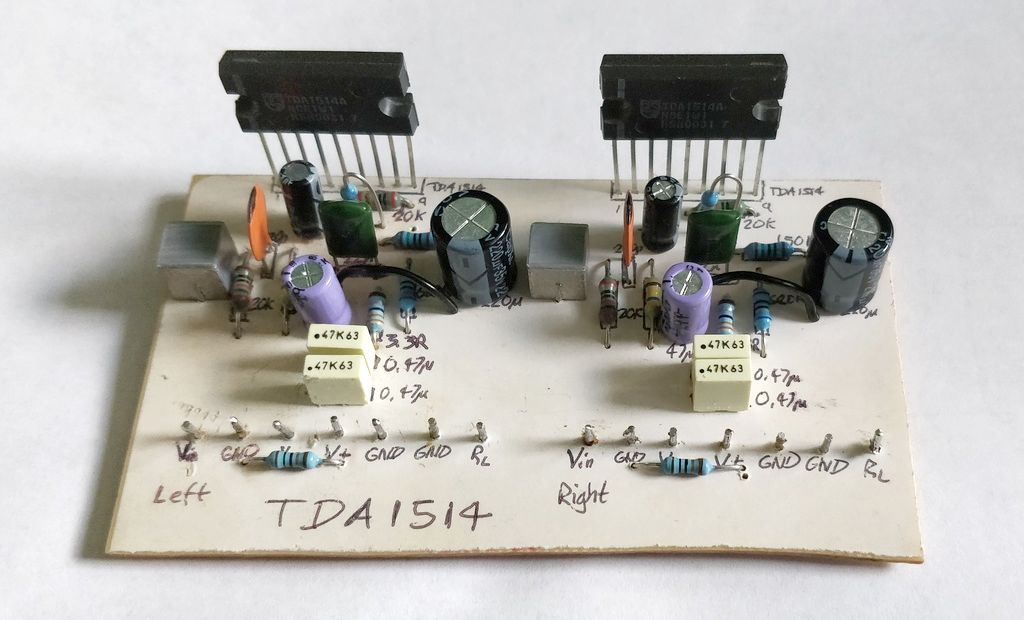
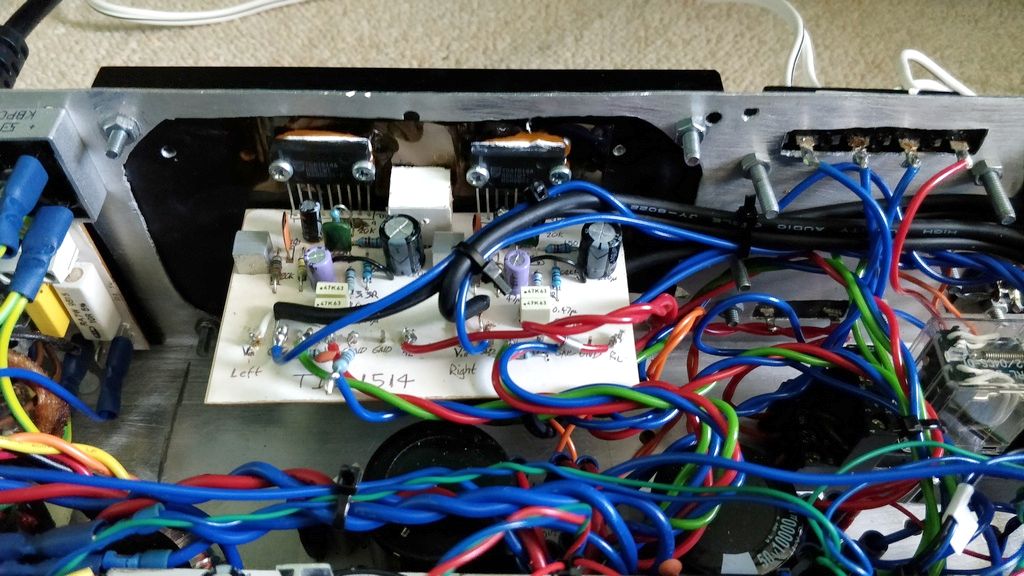
Above: TDA1514 board - I'll be adjusting and reusing this
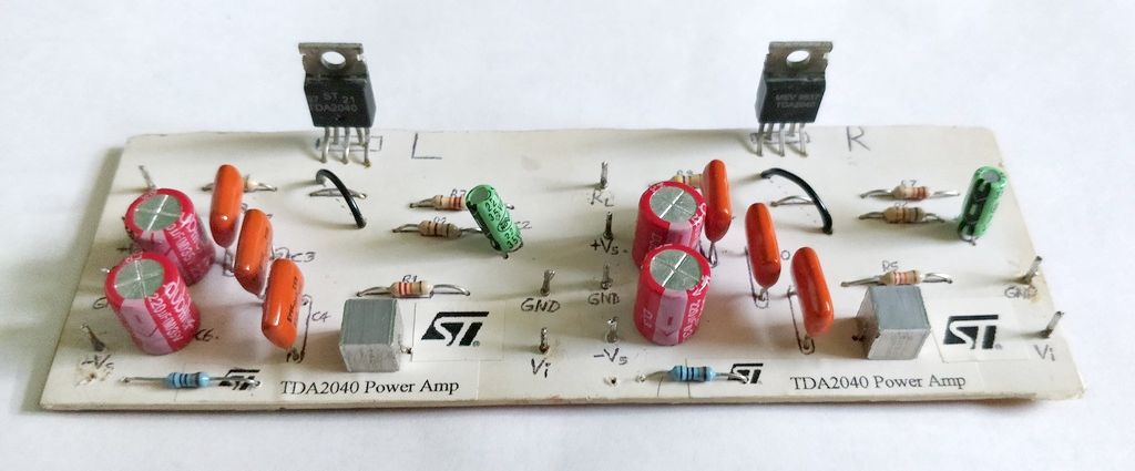
Above: TDA2040 board - originally aiming to reuse, but replaced
New and refurbished boards
Below are a few pictures of the new PCBs I built
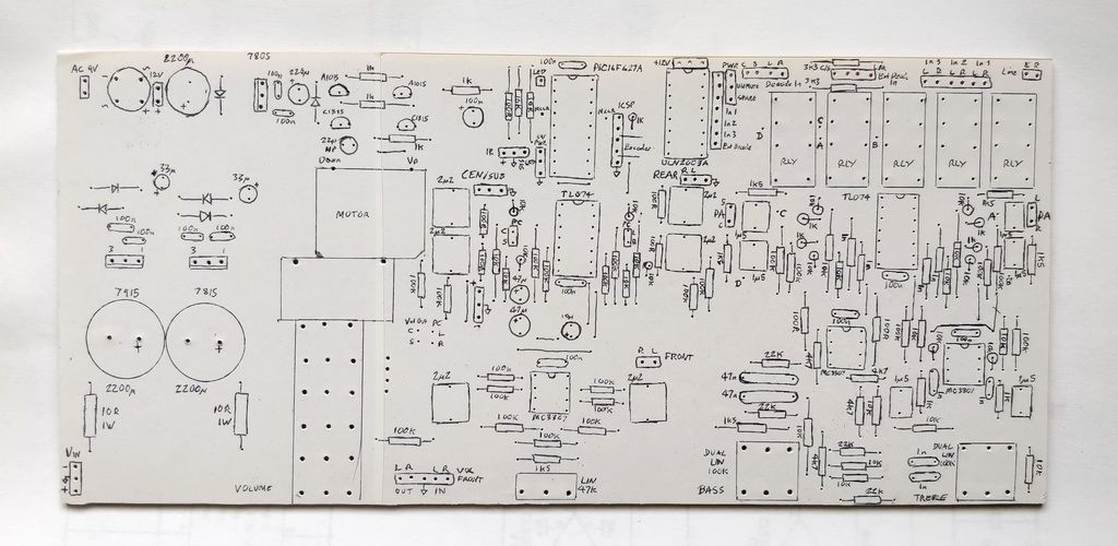
Above: Preamp board before components added
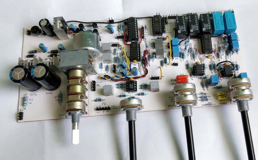
Above: Preamp board after components added
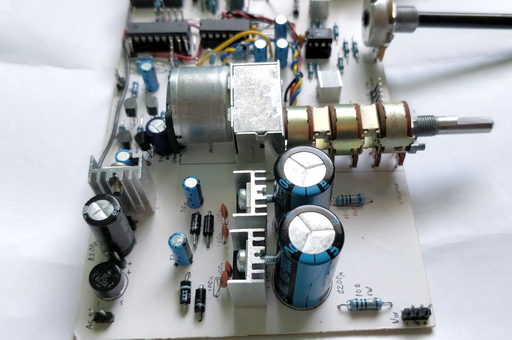
Above: Preamp board showing voltage regulators and motorised volume control potentiometer
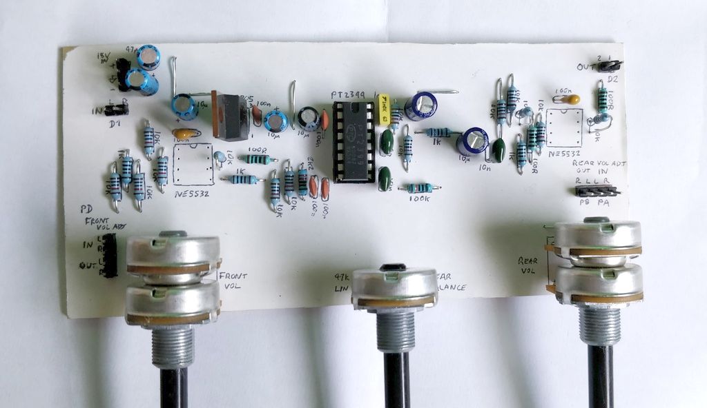
Above: Surround processor board
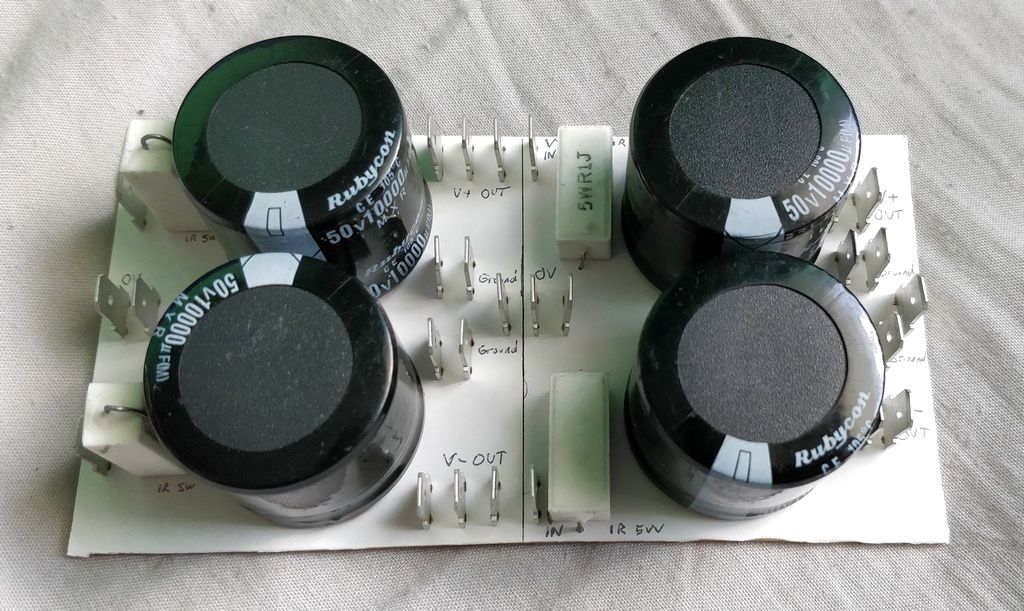
Above: Power supply capacitors
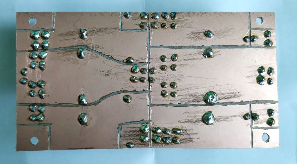
Above: Capacitors board underside
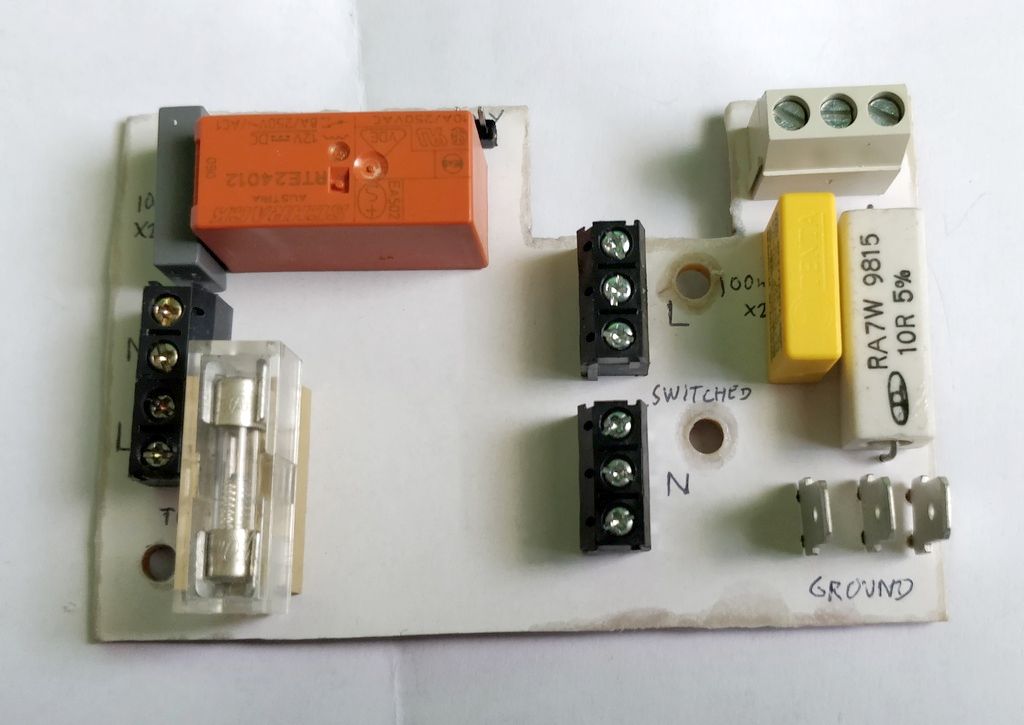
Above: Mains input and switching board
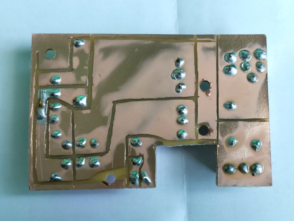
Above: Mains input and switching board underside with lacquer
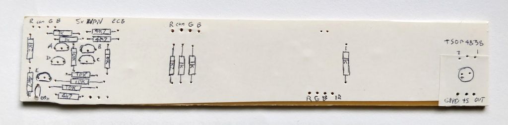
Above: LED and IR sensor board before components
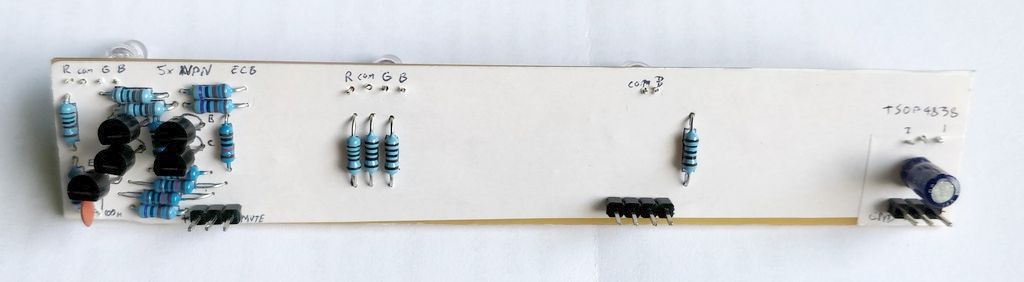
Above: LED and IR sensor board after components
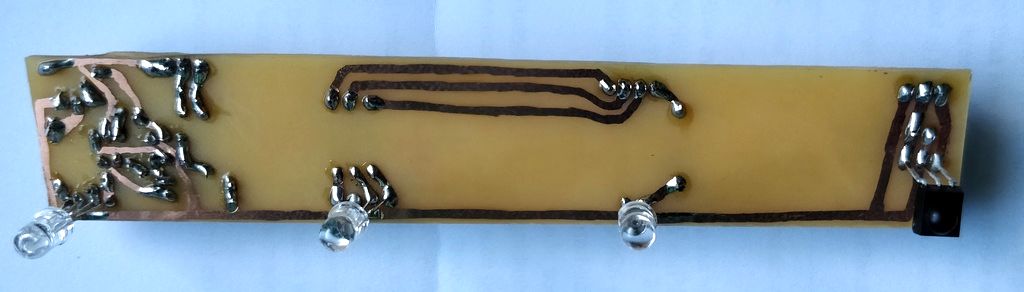
Above: LED and IR sensor board after components, back side
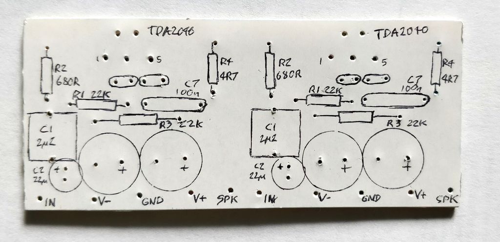
Above: TDA2040 board before components
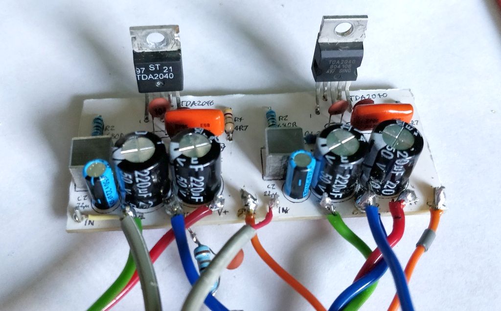
Above: TDA2040 board after components and wires
Building and results
Some pictures of the build and overall pictures of the completed amplifier.
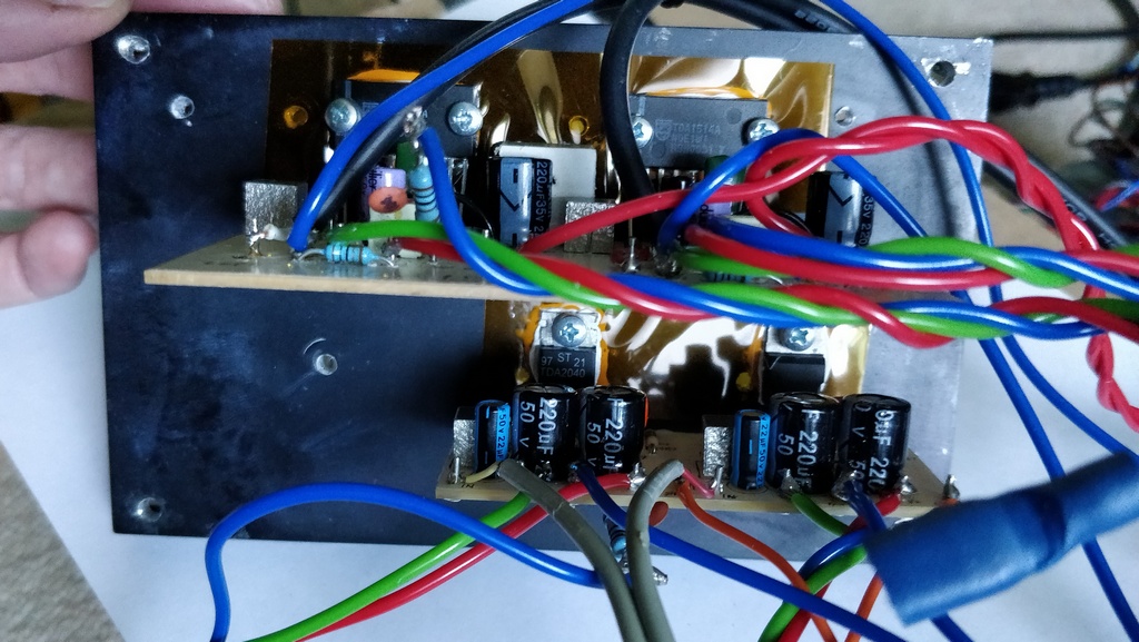
Above: TDA1514 and TDA2040 boards mounted to the heatsink
Above: TDA1514 mounted in the case. I used a square corner of chipboard to reinforce the mounting of the board to the heatsink
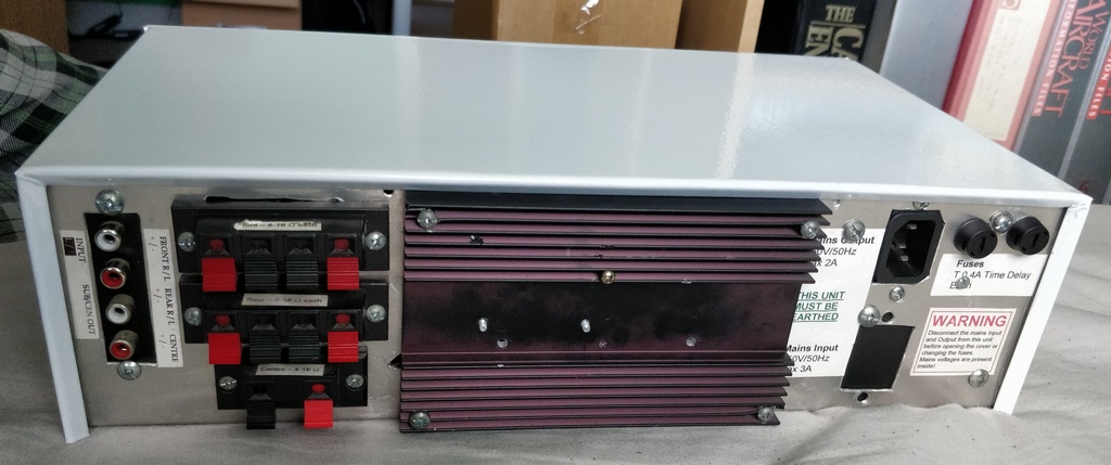
Above: Rear of amplifier - basically as it was before!
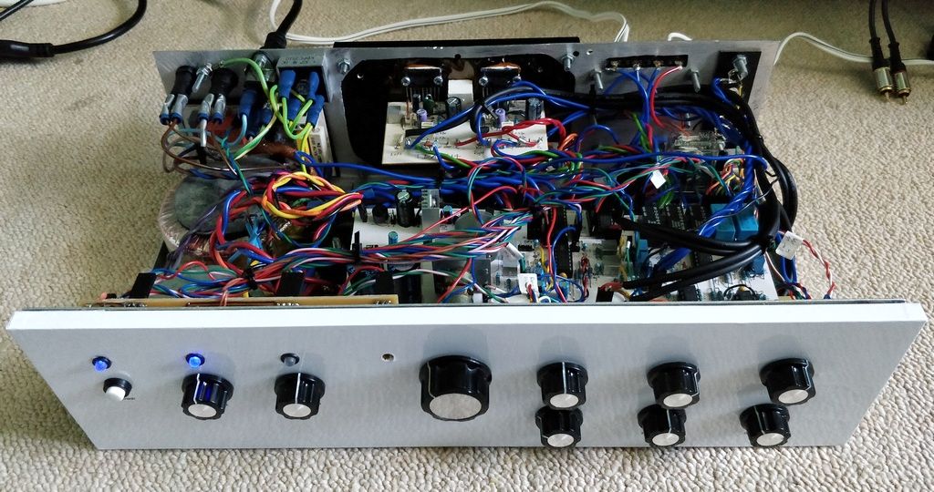
Above: Top/front view with cover off
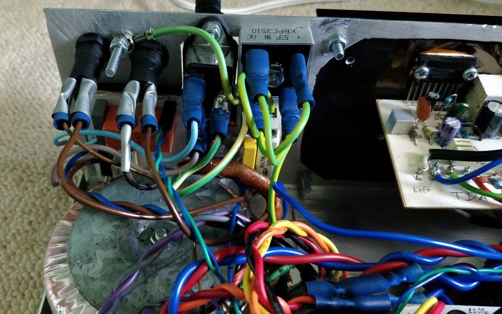
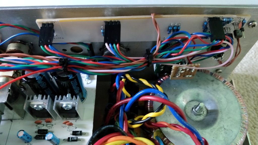
Above: Mains connectors and board. All connections made with spade terminals now instead of soldered. The 80VA transformer is below.
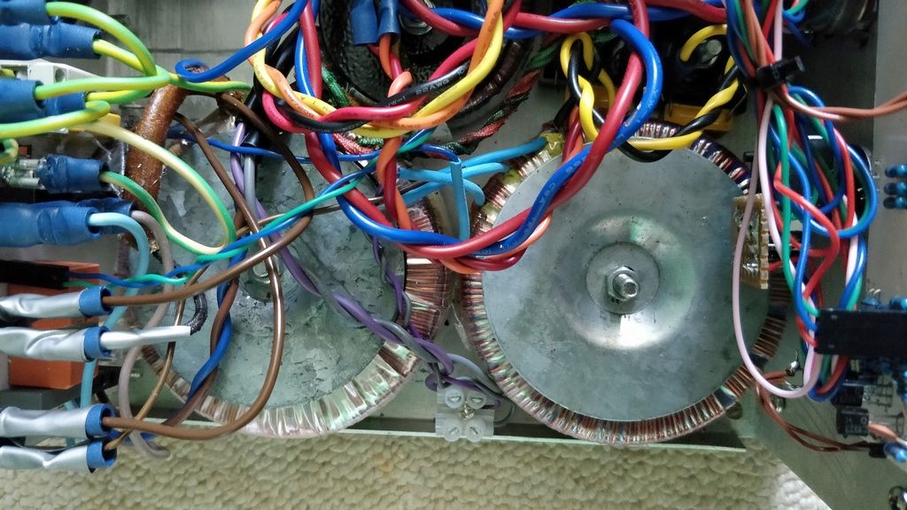
Above: The toroidal transformers. Left is the 80VA 18V one, right is the 60VA 12V one
Above: LED/IR sensor board mounted to the front of the case. The stripboard shown middle right is for the rotary encoder. On the left is the
voltage regulators for the preamp
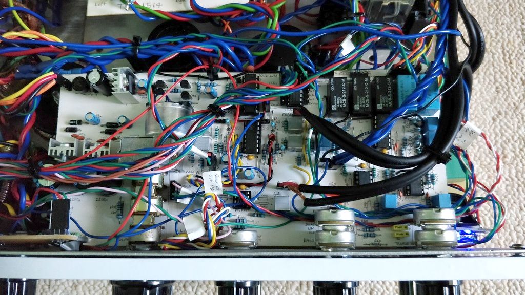
Above: Preamp board in place, showing many wires connected to it!
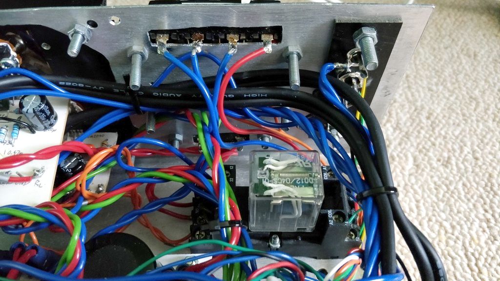
Above: Speaker terminals speaker muting relay and input connectors
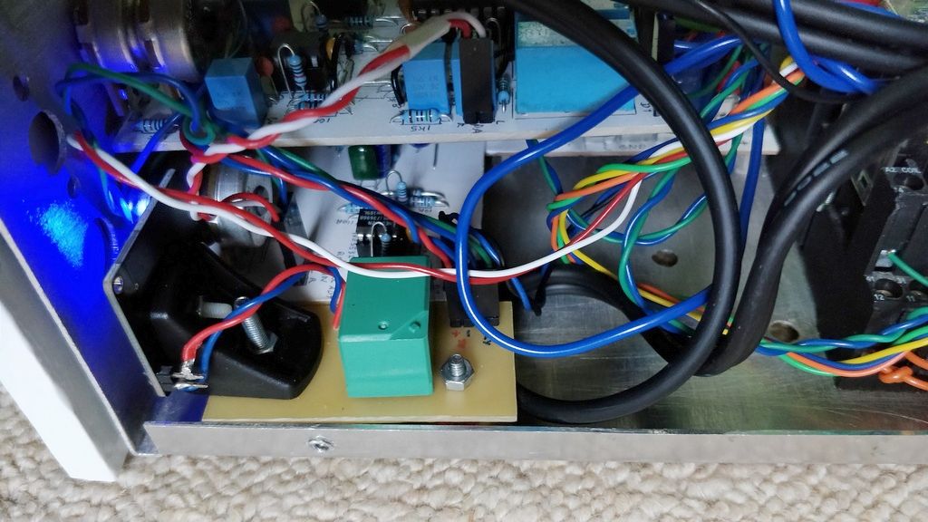
Above: Bluetooth board with L bracket to mount it vertically. The green relay switches on/off the power to this board.
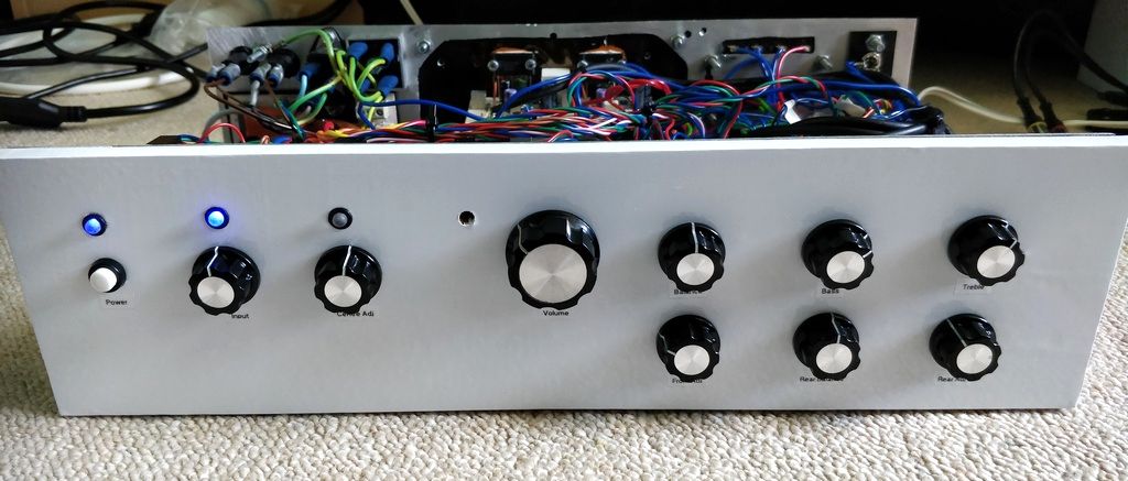
Above: Amplifier front, with labels.
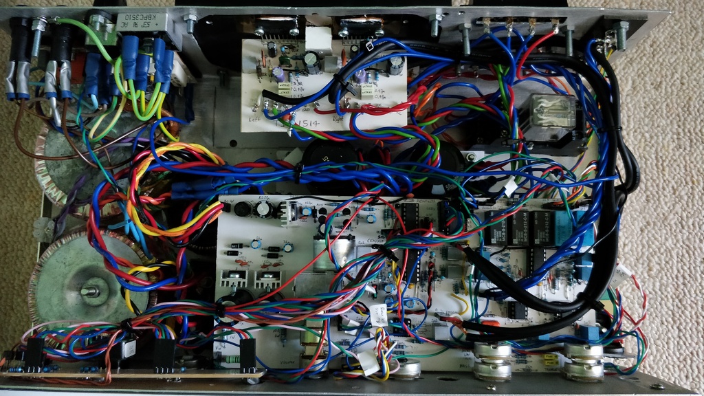
Above: Top down view with cover off.
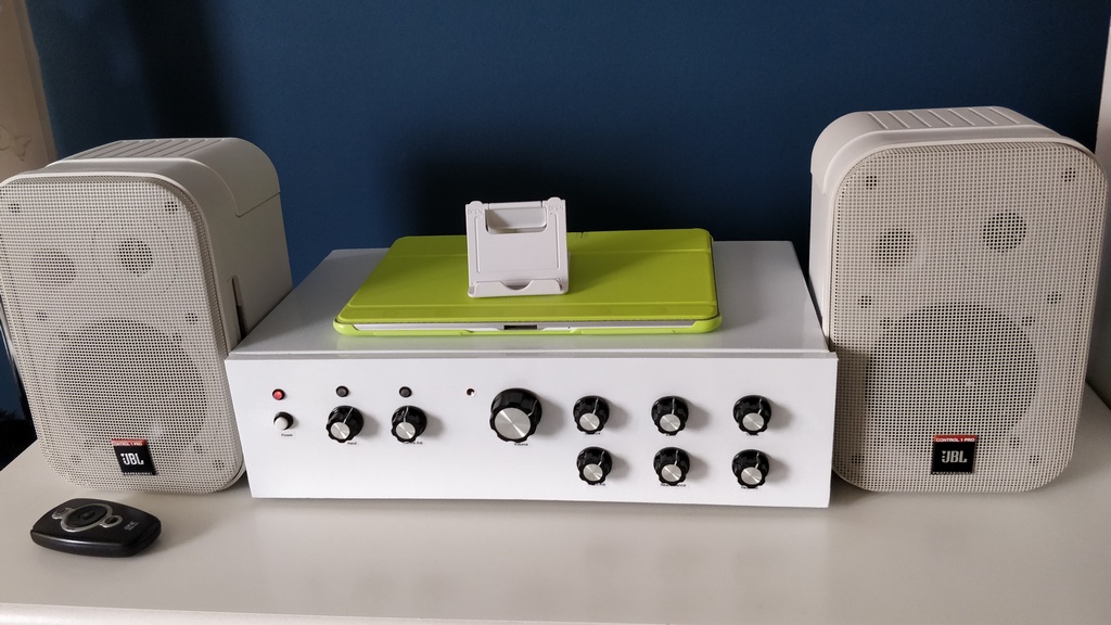
Above: Completed view, in place. I know it's not ideal placement of speakers, but they still sound pretty good there for the bedroom!
Overall, I'm happy with the rebuild. The white sticky back plastic gives it a refreshed look, but most importantly the improvements in the electronics give it remote control, improved safety and it still sounds really great! Here;s hoping it stays with me and works for the next 18 years and beyond!