
TDA1514/TDA2040 Surround Sound Amplifier - Mark 2 - Surround Sound Amplifier Remake
Part 3 - Further Building
Construction brought me up to the stage below:
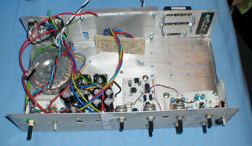
Most of it all was accommodated now. The rotary power switch went in on the left, where the old latch switch used to be (it fit in the hole rather snugly) and the mains wires go to it from the IEC 3-pin mains input socket and leave from the switch to an IEC 3-pin mains output socket. This means if I require it, I can have another device switched by this amplifiers' power switch. From this outlet socket were to be the mains leads trailing to both transformers, with each of the fuses in series with the live mains lead (one fuse for each transformer). Only transformer is shown in the photo above because the other was on order at the time. The transformer AC outputs were to be wired to the bridge rectifiers that are bolted to the bottom, just above the PSU board.
Speaker connectors and input phono sockets where put in place, but these would not be wired until later. All the potentiometers were mounted at the front also, but to be wired. From left to right, the top 4 are main volume, front volume, rear volume and centre volume. Further right the old headphones out board found its new home, which was ideal because most hi-fi devices have the headphone out in the far bottom right corner, so I was happy there :)
Switches and LEDs
A small board was made to house my rear and centre amplifier power cut-off switches and LED's to indicate their power and the unit's overall power. This was a simple board to build, only requiring the latch switches and resistors for the LED's. The result is below:
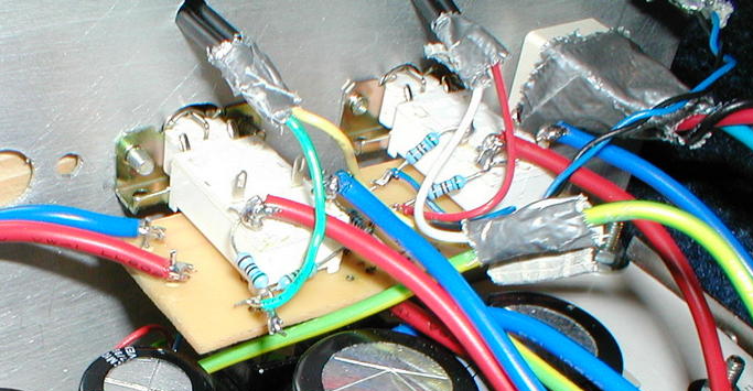
Well, the resistors were originally on the board, but I had to experiment a great deal because those blue LED's are far brighter than standard LED's, especially when viewed head on. It soon got irritating when the blue glare got in the way when watching a film in a darkened room, I had to do something to reduce the glaring brightness :(
Final wiring
From this point on, it was a matter of wiring before the main part of the amplifier was complete - the electronics. I had already tested part of the circuits separately to see if they worked, but once the wiring was complete, testing them altogether was the big moment!
As far as my success goes - it was a success. All parts worked together quite well, but there were some issues:
Strangely, the rear right wasn't working like the rear left. I took the circuit board out the amplifier and examined it again and very carefully checked everything for short circuits or breaks where there shouldn't be, but all seemed perfect. In desperation, I ordered new op-amps. I replaced them one by one and noticed that the problem was fixed after a while. Dud op-amp then, hmm, glad I gave them all sockets so I didn't have to de-solder and re-solder now!
As mentioned, after about 20 minutes, that 35V capacitor across 50V said enough is enough and went out with an alighting bang! So that was another replaced component, this time with the necessary 63V rating.
The replaced parts didn't stop there. I had a few noisy potentiometers that made an awful noise when turned - so they were replaced.
Finally, my wiring became an issue when one volume control went the opposite way then the de-facto standard, an issue easily solved, and one of my LED's was not working because I had it wired in the wrong way. Don't know how I managed to do that!
Front panel
I brought some wood to begin on a new front for the amplifier. This was aimed to hid those nuts and bolts that held the switches and potentiometers to the front, and also to hide the holes that were left from the old design. And also, cheap fablon (black sticky back plastic) was not going to be accepted anymore by my higher quality demands!
My first attempt was ok, but my measurements were a bit off and the wood was too thick. At this time, my mate was round and he does carpentry at a local college, so he said he would do me a new front using better tools and a nicer bit of wood that he could get for free and plain down to my exact width needs.
This new bit of wood went on quite nicely, though I did have to make some holes wider myself, but it was a nice attempt going on nasty measurements (my fault).
I didn't want to use the cheap method of labelling like I did on my old amplifier - printed labels from the PC. But in the end, that's what I did and it actually looks quite alright. The wooden front, silver knobs and black switches gives it a nice retro look :D
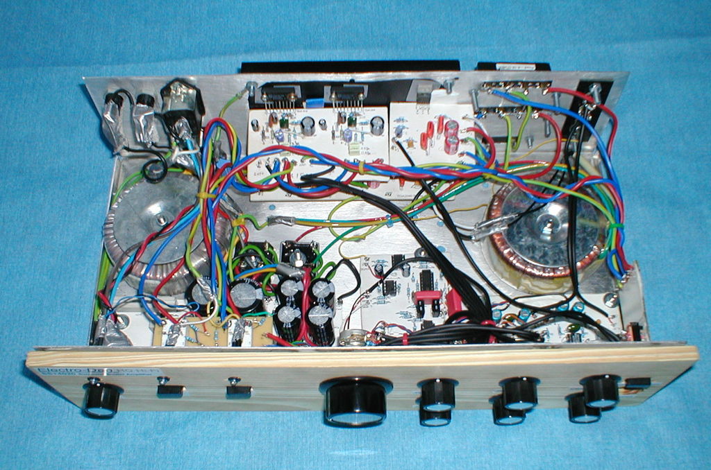
Above is the completed amplifier. You can see how it all went together and how the new transformer went in on the right (this was not actually here at first, but I only have a recent picture) and all the amplifier circuit boards all mounted nicely on the back heatsink. The wiring was much neater than my old amplifier I feel and it met most of my standards.