
LM383 / TDA2003 / TDA2002 / TDA2008 DIY Guide - 10W to 12W Single Supply (Car Radio) Amplifiers
This article now combines information for all these chips - you may been redirected here from the TDA2003 article.
Warning: These chips have all been discontinued and are susceptible to fakes. If you're buying, make sure it is from a good supplier (i.e., not auction sites) to get the genuine chip otherwise performance will be bad, the chip may be easily damaged and create a hazard, or hum/buzz may be worse than the official chip.
Recommended Experience : lower intermediate, knowledge of amplifiers, PCB etching, heatsink attaching, and (optional) mains qualification
Comparison
All of these chips are 5 pin Pentawatt (TO220 similar) devices that basically operate in the same circuit, with minor differences in component values.
Quick facts
- Class B
- Speaker support down to 1.6 ohms (3.2 ohm for TDA2008)
- Short circuit protection
- Frequency Response 20Hz to 100kHz
- Gain: 40dB using datasheet components (adjustable ~24 to 40 dB)
Performance difference
The table below is a comparison of key performance differences. Note that the voltage range is from absolute minimum to the absolute maximum limits - for reliability, you should aim to use a voltage supply that is 2V under that limit.
| Package | Voltage supply range | Power at 10% 1kHz THD - 4 ohms | Power at 10% 1kHz THD - 2 ohms | Power at 1% 1kHz THD - 4 ohms | Power at 1% 1kHz THD - 2 ohms | THD at 2W 1kHz - 4 ohms | Peak current limit |
|---|---|---|---|---|---|---|---|
| LM383 | +/-6V to +/-15V (+12V to +30V) |
5.5W from +14.4V | 8.6W from +14.4V | 3W from +14.4V | 5W from +14.4V | 0.2% | 3.5A |
| TDA2003 | +8V to +18V | 6W from +14.4V | 10W from +14.4V | 5.2W from +14.4V | 8.5W from +14.4V | 0.15% | 3.5A |
| TDA2002 | +8V to +18V | 5.2W from +14.4V | 8W from +14.4V | 4.3W from +14.4V | 6.6W from +14.4V | 0.15% | 3.5A |
| TDA2008 | +10V to +28V | 12W from +18V | - | - | - | 0.12% | 3A |
The TDA2008 is an odd one out in that it supports a higher voltage and shows a performance of 8W into 8 ohms from +18V (not shown above), but it has a lower peak current handling, but also slightly lower distortion.
Otherwise, if your build is for lower voltages, than the TDA2003 is the best of the rest.
The TDA2002 is the predecessor to the TDA2003 from SGS, dating to the late 1980's. It's still intended for the same use - car radios but could be used anywhere a simple single supply amplifier is needed. The performance is not as good as the TDA2003 above, but if you have it, it could still be useful as an amplifier.
The LM383 sits between the original TDA2002 and the updated TDA2003 chip. Again, it's old, dating to the mid 90's. It's still intended for the same use - 'automotive' applications (car radios) but could still be used anywhere a simple single supply amplifier is needed. The power performance is between the TDA2002 and TDA2003, but the distortion performance is worse.
Datasheets
Guide
The TDA2003 was my first amplifier build on a PCB, way back in 1996 (I was just 13 years old), thanks to a Velleman kit from Maplin. Add one speaker and 9V worth of batteries and I was playing music off my own and other peers cassette and CD players and annoying other people on the bus long before the current generation do from their smartphones!
The TDA2003 and its older brothers TDA2002 and LM383 are cheap amplifiers that are designed to run on single rail power supplies only. It has many applications including in car systems (if you do not need to show off down the high street with your high power subwoofers!) and is protected against short circuits.
It is a mono amplifier and single ended (not bridged). The TDA2005, TDA2004 and TDA2009 are stereo/bridge alternatives (not covered here). TDA2004R and TDA2005 are still in production too!
The TDA2003 is the only amplifier I've actually built (three times in my life), but for all the chips, here are some applications it would be happy to work as:
- A pair can form a capable amp for a stereo system (i.e., a homemade or upgraded midi system or 'ghetto-Blaster', although battery operation may not be the best).
- A pair can be used to improve the sound from a TV.
- Beefing up those 400W+ amps in PC speakers (seriously)!
- Bi-amp or tri-amp systems.
- Bluetooth speakers.
- Music instruments i.e., Keyboard, Theremin.
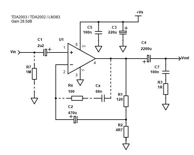
This amplifier schematic is based on the typical application in the ST Microelectronics datasheet, however, the high 101x gain of the original has been reduced to a more reasonable 26x by adjusting the values of R1 and R2, as well as Rx and Cx. I've also increased the value of C3, C4 and C1 for better power stability and bass performance, as well as added an optional resistor R7 which may be needed if your source has its own DC blocking capacitor.
The performance from this circuit is satisfactory and with sensitive speakers this amp can give you loud music, but its power output isn't amazing. Output power into 8 ohms isn't shown anywhere but expect it to be about 3 to 3.5W at 10% distortion - about half the 4 ohm power.
The TDA2003 can drive speakers with impedance down to 1.6 ohms, where it can produce 12W (high distortion). I've never heard of a 1.6 ohm speaker though, but 2 ohm speakers do exist, and they might have an impedance approaching this in reality. 10W can be expected in this case, again with high distortion. Two 3.2 ohm speakers in parallel is another scenario, or maybe an 8 ohm speaker plus two 4 ohm speakers all in parallel!
For best power, I suggest the bridge circuit is used. In BTL form, you get nearly four times the output into the same impedance. For example, a single TDA2003 can give 6W into 4 ohms, but two TDA2003 chips bridged will give 20W into 4 ohms. BTL needs two TDA2003 chips and more components, but doesn't need that 1000µF (or higher) output capacitor which is costly, space consuming and reduces bass.
The circuit is very simple, and design isn't too critical, however you will have problems with Veroboard / Stripboard mounting due to its pin layout. It is possible, but you will find this amp a lot easier to build on a PCB. The PCB layout suggestion in the original datasheet is a mistake copy of the bridge version, so don't use that, however a more up to date TDA2003A datasheet does have the correct layout but note that C3 (the 100uF) bypass capacitor is not included. I suggest extending the board further right and locating C3 to the right of C5. It needs to go from +Vs to ground.
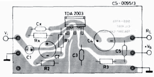
Note: The above image is copied directly from the datasheet and is not mine, nor is it likely to be 1:1 scale. To achieve this scale, the best idea is to print to PDF file to A4 paper. Please use the datasheet to view the schematic and the component values.
Components
| # | Type | Quantity |
|---|---|---|
| U1 | LM383, TDA2002, TDA2003 or TDA2008 | 1 |
| R1 | 120 ohm Resistor, ¼W Metal Film, 1% | 1 |
| R2 | 4.7 ohm Resistor, ½W Metal Film, 1% | 1 |
| R3 | 1 ohm Resistor, 1W Carbon, 5% | 1 |
| Rx | 100 ohm Resistor, ¼W Metal Film, 1% | 1 |
| R7 | 1M ohm Resistor, ¼W Metal Film, 1% | 1 |
| C1 | 2.2µF Capacitor, Polyester Film/Box (Best) or 16V+ Electrolytic (100nF or higher is also fine) | 1 |
| C2 | 470µF Capacitor, 25V+ Electrolytic (use 35V+ for TDA2008) | 1 |
| C3 | 220µF Capacitor, 25V+ Electrolytic (use 35V+ for TDA2008) | 1 |
| C4 | 2200µF Capacitor, 25V+ Electrolytic (use 35V+ for TDA2008) | 1 |
| C5 | 100nF Capacitor, 50V+ Ceramic X7R or MLCC | 1 |
| Cx | 68nF Capacitor, 50V+ Polyester Film | 1 |
| C7 | 100nF Capacitor, 50V+ Polyester Film/Foil/Orange Drop (Best) or Ceramic X7R | 1 |
| In, +Vs, Spk | 2.54mm header 2-pin | 3 |
| Heatsink, cable, connectors | ~ |
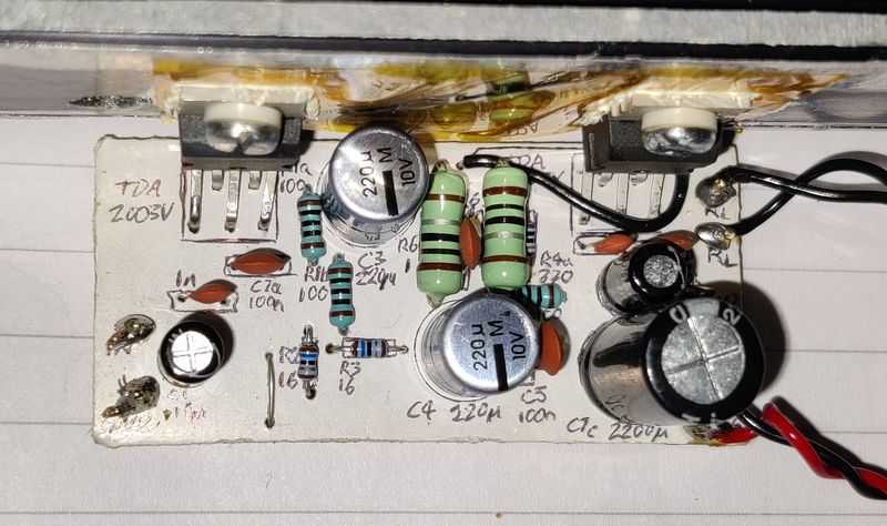
Resistor are recommended as 1% metal film, but as the picture of my prototype shows below, 5% resistors are capable. R2 and R3 are low value resistors, and you should try and get close tolerance resistors for these, as well as using ½W or 1W resistors to ensure they'll comfortably handle heat when larger current is drawn.
Capacitors should be electrolytic above 1µF and rated at 25V minimum, or higher for applications where the load dump surges may momentarily peak (e.g., 35V to 50V). They must all be connected the right way round or failure and possibly injury will follow when the amp is powered up.
The gain is set by R1 and R2, which is 1+(R1/R2) in gain voltage. Using the default values in the datasheet that is 1+(220/2.2) giving a gain voltage of 101. In decibels, that is 20*log(101) = 40dB. That's a very high gain! At this gain, a 50mV RMS signal will output 6W into 4 ohms, which is pretty much its maximum power. It means this chip is unlikely to need a preamp and is probably intended to be hooked directly to an FM output or tape output, which is what all car radios had in those days!
Reducing R1 will reduce the gain. To get it to a more standard 30dB, R1 needs to be reduced to 68 ohms. That's a really low value for a feedback resistor though and drain current will be increased. Alternately we can raise the value of R2 above 2.2 ohm, however this degrades supply voltage rejection (SVR).
A reasonable compromise would be to reduce/increase both to say 120 ohm for R1 and 4.7 ohm for R2. This gives a gain of 26.5x, or 28.5dB.
Rx and Cx are needed for stability/high frequency cutoff and must be worked out using the data sheets mathematical calculations. Calculate Rx first, which is 20 times R2, giving 44 ohms (39 ohms is the closest). Cx is 1 / (2 × π × B × R1) where B is the frequency cut off and R1 is 220 ohms by default. Using 20kHz; 1 / (2 × π × 20000 × 220) gives 3.6E-08 - that's 36 nano farads (nF). 33nF would be fine, giving a cutoff around 22kHz, or 39nF would give us 18.5kHz.
If you went with less gain and picked 150 ohm for R1, 4.7 ohm for R2, then Rx/Cx will be different. Rx would be 20 × 4.7 = 94 ohm (pick 100 ohm) and Cx would be 1 / (2 × π × 20000 × 120) = 66nF (pick 68nF).
For accuracy, use a 1% resistor for Rx. The capacitor Cx can be a ceramic capacitor.
For C3 (bypass capacitor) and C5 (Zobel capacitor) - these should be ceramic or multi-layer ceramic (MLCC) capacitors.
A heatsink is important. The one shown in my prototype is actually too small and you should obtain something bigger for improved operation.
Power Supply
12V single supply power supplies are plentiful, and 16V can also be found which will give more power. I don't recommend going higher than this. You can purchase a great deal of 12V to 16V external power supplies that will happily provide the TDA2003 what it needs. Make sure they are rated for audio or video, otherwise noise and ringing will be heard through the amplifier. Laptop PSUs work well but be sure their voltage isn't too high as most are around 19V.
The power output of a PSU will vary depending on your load, and the number of amplifiers. At the highest end of the scale, you're pushing 1.6 ohms with +16V Vs, which will put 15W into the speaker and more than 6W of heat, so (because we need some margin) 30W would be required - go for a 2A 16V PSU. Into 8 ohms from +12V, power output is unquoted, but will be small (less than 3W) - so an 8W PSU or higher would work (that's 12V at 0.67A).
Double the power supply current / power for a stereo amplifier, or bridged amplifier. Quadruple it for a stereo bridged amplifier (i.e., 4x TDA2003s)!
Alternative, you can build your own PSU, but before wiring a power supply, take note of this:
THE POWER SUPPLY REQUIRES MAINS VOLTAGE WIRING. DO NOT WIRE IT UNLESS YOU ARE SUITABLE QUALIFIED, DEATH OR SERIOUS INJURY MAY RESULT.
If in doubt, do not wire your own PSU with transformer and get a pre-built one.
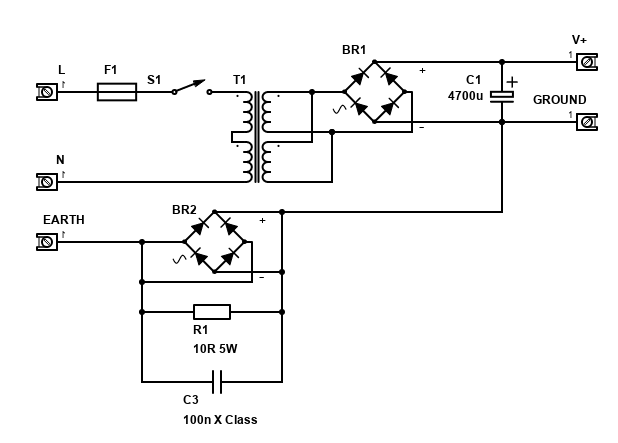
The transformer should not be rated above 12V AC. This will give a 17V DC output (give or take) unregulated.
You could get away with a small transformer such as around 30VA with 2-wire AC outputs, for one amplifier. Double that for a stereo pair, or mono bridged amplifier, and so on.
The components on the earth and ground connections form a loop breaker. This is recommended construction because it can eliminate an earth loop. R1 is a 5W or better wire-wound resistor. The 100nF capacitor must be a Class-X rated for 250V AC, you cannot use a 250V DC cap as it would fail open and burn if there ever was a fault causing mains to flow to earth. Check your country's rules and regulations before constructing this as it may be illegal. If so, omit all these components and connect the earth directly to ground but never disconnect the earth lead... it could save your life or somebody else's!
Bridge Versions
There are two bridge versions available in the ST data sheet. A 20W version, and a low-cost 18W version. The LM383 also has another alternative.
The benefit of the bridge version is you'll get nearly four times the power output into the same load for not much extra space and cost - for example the 6W output into 4 ohms now becomes 20W (both with a VS of 14.4V). The large capacitor on the single chip version (C4), required to block the DC current flowing through the speaker is no longer needed as both sides of the speaker now have the same DC voltage, hence no DC current flows through it.
In bridge mode, driving 1.6 ohm or 2 ohm speakers are no longer possible - but 3.2 ohm still is. Most speakers are 4 ohms or 8 ohms anyway.
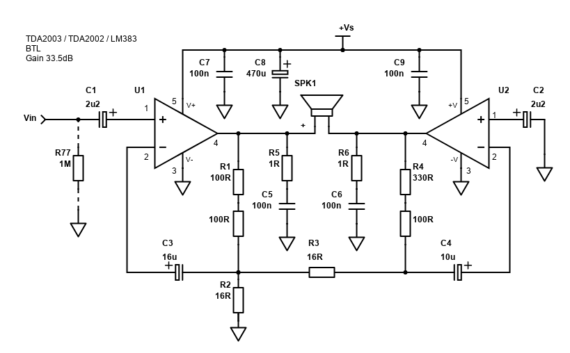
The circuit above is a bit more complex but should not pose any great layouts challenges. Again, PCBs are recommended as there are now two TDA2003 chips.
The values suggested in the datasheet may be hard to get, but they may be made up of series resistors, which I've shown above. You'll probably still need to get the 16 ohm resistors though.
Given the need for series resistors, and the some components missing from the datasheet layout - I did roll my own PCB layout based on the rough datasheet version.
I measured a gain of 47x (about 33.5dB), but in less than perfect conditions. This is a reasonable value for the gain, hence I've not suggested to adjust the resistor values.
The disadvantage of all these bridging approaches to bridging is that any distortion from the first amplifier will be feed into the second via the resistor that sits between the output of the non-inverting amplifier (U1) to the inverting amplifier (U2).
I also found my amp gave a quite seriously loud hum with no input connected. Even stranger, the hum reduced when I touched ground with my finger whereas normally it increases! With the source properly connected though, it behaves fine with only a little hum.
I would say though that the BTL version is more suited to an integrated system, i.e., a powered speaker with radio or Bluetooth all integrated rather than a separate amplifier unit.
An alternative (though I wouldn't consider it!) BTL circuit is the 'low-cost' bridge amplifier which has a smaller component count and an output power of 18W. All you need is several 0.1µF caps, plus a 1nF and a 10µF electrolytic. Put in one resistor, and there you have it - supposedly! I must add though that a did try wiring this circuit years ago on stripboard and the amp refused to work. You may have more luck than me, especially if you used a PCB instead since the ST Microelectronics datasheet does contain a stereo layout for it.
This circuit does appear to be using the TDA2003 in open-loop gain though, and even if it works, expect it to be noisy. Because it's hard for me to recommend, I'm not showing it here!
Really though, with so many BTL chip amplifiers available that operate off 8V to 18V DC, my suggestion would be to use these instead unless you happen to have several of these chips already and want to use them! Examples: TDA2005, TDA7391, TDA7297 (stereo), TDA7375 (stereo).
Performance and Prototypes
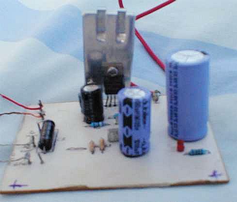
My original prototype (around the year 2003) worked well. Above is the best of the awful photos I still have of it! This board not only includes the amp, but its power supply and a very simple passive crossover (that's the axial electrolytic you can see bottom left). This allows a woofer and tweeter to be added with ease in the proposed system. You may notice the pins on the TDA2003 chip - they are spread out like they have to be when stripboard mounting. This is because this chip was used on my stripboard bridge version that failed.
Inputs are also on the left and the AC is the green and white wires appearing at the back. You can also see an LED at the front, this was to ensure me that everything in the supply was fine. The large 4700µF and 1000µF capacitors hide a few of the components.
The sound is pretty good, with response across the audio spectrum. This amp will not go very loud though, especially into 8 ohms, turn it up and it will clip.
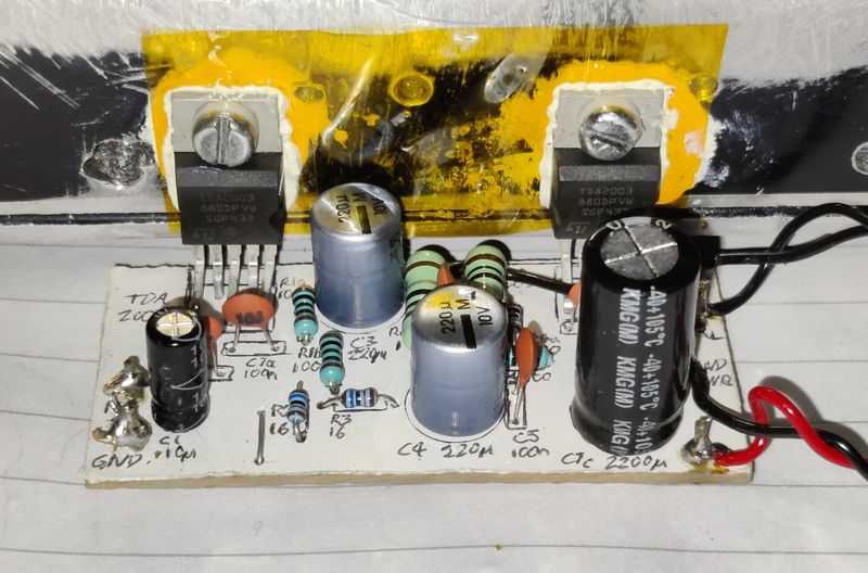
I also built a BTL version around 2011, which I still have today and still works. This also performs fine and can drive 4 ohm speakers with ease, but I never really used it. One day it might serve a purpose though!
LM383 notes
The schematic above and the advice is pretty much the same, so just read it all! National Semiconductor don't include the stability components (Rx and Cx) in their schematic, but my advice is to include them. They also, strangely, use 200nF as the value for C5 and C3 - 100nF will be fine here, but 220nF is also a common value if you want to feel better! They also show 2000µF output capacitor (C4) - you can use 2200µF here, or 1000µF is OK for a 4 ohm speaker (cutoff will be around 40Hz).
Finally, National Semiconductor have not shown a bulk electrolytic on the power supply line for decoupling. I suggest this is added too. 100µF or higher should be used in parallel with the 100nF (0.2µF capacitor in their schematic) connected between pin 5 and ground.
The typical bridge application is different from both bridge configurations that the TDA2003 suggests and includes a 100k potentiometer which is used to adjust the DC voltage offset. If you build this circuit, before you connect a speaker, measure the DC voltage between each terminal and ground - they must be the same and adjusting the 100k potentiometer (this should be a trimpot) to make the DC voltage on the right most terminal equal to the left.
Again, if you build National Semi's BTL application, add an additional 220µF capacitor (or higher) from the power input to ground. The 200nF (0.2µF) capacitors can be safely substituted for 100nF.
If you obtain two LM383s from the same system or supplier, they are probably well matched enough to work in the TDA2003 bridge circuits above.