
PC Fan Controller
This page has been updated...
The following article is a supplement to an article already on the web at the following address:
http://www.bit-tech.net/article/32/
I have built mine own version earlier this day and my findings and suggestions are presented below:
The circuit shown includes a power LED, a power switch, 4 controllers each with their own LED. Although this will give a nice setup for serious PC modder's who want control over each of their 4 delta fan's :-)
Myself, well I only have extremely cheap 80mm fans (they came out of dead AT PSU's), and I decided that one LM317T regulator would do all 5 fans with no trouble. So I have adopted a much cheaper approach to the solution and also smaller too. I will also show you how I connected the circuit board to the spare blanking plate in my last 5.25" drive, and give a sample layout for stripboard PCB.
Update: Note that an LM317T regulator is a linear regulator and has a drop-out voltage of up to 2.5V. This means even at the maximum adjustment, the fans will receive only 9.5V, not 12V.
First, this is a list of what I needed...
- An LM317T IC (maplin now sell these for £0.49) [UF27E]
- A 1k miniature potentiometer (closest to 2k as you can get - £0.49) [JM69A]
- I thought a yellow LED would look nice (£0.10) [WL30]
- Resistors (I had a 270 ohm and a 220 ohm so I used these values) [M270R] [M220R]
- The other components I used (and that I had already) were an aluminium heat sink with mica washer and nylon screw/nut, a DPDT slide switch, a power connector for the PC motherboard and some wire.
- I plan to get an aluminium finish knob for the potentiometer to improve its looks a bit (£1.29) [YR64]
This gives me a total of £2.37. For others the bill wouldn't exceed £5-£7 depending on the need for wire etc. This makes this circuit a very cheap and useful addition to your PC. I have the fans set on low at the moment as my desktop is just being an internet server at this moment as I am writing this article in bed on my laptop. Its nice and quiet and you don't realise how loud it used to be until you switch the fans to full.
The circuit I used is below, its a simplification of the one on the page above using only 1 controller:
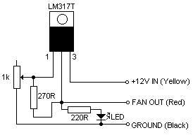
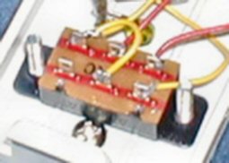
Because of the simplicity of this circuit, it can easily be laid out on stripboard as shown by the pictures below - this board is indeed very small and gives me plenty of room. The stripboard circuit shown does work, but the potentiometer is wired differently as I found that anti-clockwise speed up the fan and vice versa - I wanted the opposite. Note: The schematic above should be the correct way round, unlike the stripboard layout:
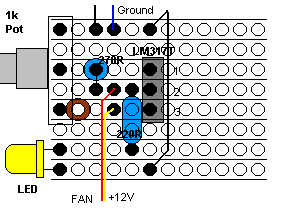
Viewed from above
If you want to use this layout, which works well except for the reverse directions on the potentiometer, then below are further details you will need to know.
It horizontal line is the break in the strip of copper, with each circle obviously being each hole in the board. Where a circle is filled black is where you would insert component pins and solder them the the copper strip behind. When soldering, do not use much heat, the components are not very forgiving.
The brown circle is where you need to break the copper track behind. You can buy special tools to do this neatly - but I just used a 2.5mm drill bit and went it slowly until the copper had been removed. Do not go through the whole board. Another alternative is to chop that un-needed pin of the potentiometer - a bit like it is done in the article. It will then not need to be soldered at all and two pins should give you enough stability.
Resistors are the blue coloured ovals. The 270/240R one is wired vertically, just insert the first pin, the bend the next one through 180 degrees and insert it in the hole next to the first pin.
The resistors are not fussy about which way round they go, however the rest of the components are. It is unlikely that you will get the potentiometer the wrong way round, however the LED is easy to get wrong. There is an anode and a cathode - the anode must (longer lead) must connect to the resistor, whereas the cathode (short lead) goes to the wire that leads to ground (that's the bottom strip on the board).
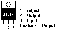
The regulator must also go the right way round, pin numbers are shown on the board diagram and pinouts are shown below, viewed from the front of the chip:
Finally, connect the wires. They will need to be stripped of the insulation by about 3mm, then soldered to the board, carefully. Don't forget the wire that runs on the right of the board or the LED will not work (its needs ground).
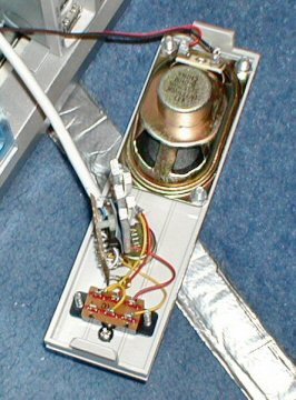
Pictures of the board I produced are below:
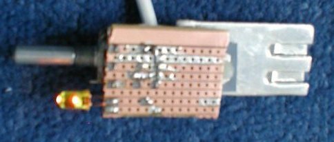
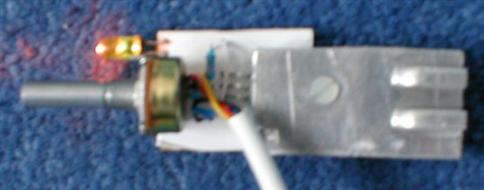
The heatsink I used was fairly big in size and it is unlikely that something would be needed quite this big, the device seems to run cool. The pictures also show the yellow LED glowing.
Tests
I used an unregulated PSU at 9V (which gave me around 12-13V under little load) to see what this circuit can do. At maximum voltage I got the following reading:
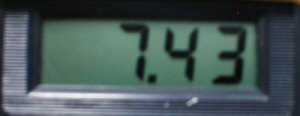
This voltage seemed a little low considering the article says it should reach a maximum of 10.5V. I suspect that the different value components would have something to do with this - such as a 1k potentiometer rather then 2k and a 270 ohm resistor rather then 240 ohm (didn't have one of those). At minimum, the voltage became this:

This is almost as expected - and at this voltage, the LED does not glow and any 12V will definitely not spin. Adjusting the voltage seemed quite linear and the circuit does give you a good degree of control between these two voltages.
Mounting the circuit in my PC
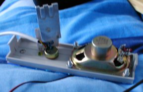
I decided to "mod" the spare blanking plate I had since I am unlikely to need that forth 5.25" drive bay. You may also notice that I have mounted a speaker on this too. This is because my case came with no speaker or anywhere to attach one and instead came with a very small piezo sounder mounted on some leads for the normal bleeps a motherboard sends. However, my motherboard also talks (Asus A7V333) and it is handy to here the voice clearly when diagnosing faults. I may also plan to put a mono amplifier in place so I can switch to sound card output amplification in case I would ever need it. Here are some pictures of all the holes I drilled for my plate:
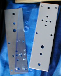
All separate - the silver backing, the blue acrylic and the grey plastic
blanker.
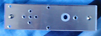
All three parts mounted together.
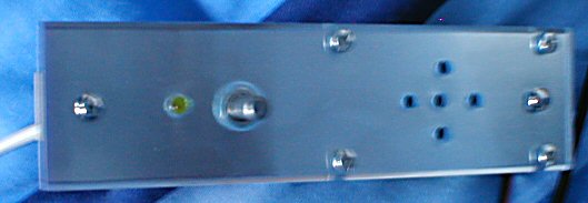
With speaker and fan controller added.
View from the back.
When drilling holes for blanking plates similar to mine, you need to make sure that you mark and drill on the front. I wasted one of my spare plates as I found out that the acrylic is easily cracked when it is drilled from behind. Also, the potentiometer will not reach through the plate fully, so I had to sink a larger hole in the front to recess the mounting nut. I used a high speed drill bit to do this - if you do too, make sure you do the recess before the hole, other wise you will have a 7mm hole which does not provide anyway for the high speed drill bit to guide into (it makes it own, smaller initial hole). Once the recess is done, you can then widen the hole it leaves with a drill bit.
Adding a bypass switch
After installing the device in the PC, I decided that at maximum speed, my fans were not spinning anywhere near as fast as they used to. I found a spare DPDT (Double Pole Double Throw) slide switch and decided it would be a good idea to install that to bypass the fan controller and give me maximum speed when desired. Wiring it up is shown below:
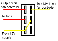
Making the hole for a slide switch is much more difficult then a toggle switch, so if you are going to maplin, or your local electronics retailer, get a toggle switch, you can wire a DPDT one in exactly the same way. Pictures of my wiring and handy-work for the slide switch are below:
The back of the whole plate with extended wiring for the switch.
Wiring on the switch itself.
Conclusion
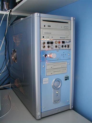 The picture on
the left is my PC tower case with my new mod in and working great. At the moment
the switch is selected up - which enables the fan controller. At maximum speed,
it is enough to make all the fans almost inaudible compared to the processor
fans and hard drives.
The picture on
the left is my PC tower case with my new mod in and working great. At the moment
the switch is selected up - which enables the fan controller. At maximum speed,
it is enough to make all the fans almost inaudible compared to the processor
fans and hard drives.
When my CPU temperature starts to get to a point which I am not happy with (about 55 degrees perhaps), I can throw the switch and my fans will speed up to maximum speed as they get the whole 12V they need to run fast. This switch also turns off the fan speed controller and the LED goes off.
I am also happy with the speaker, 5 holes is enough to hear the diagnostic voice audibly and it sounds clearer then I have ever heard a PC speaker before - maybe I will do an amplifier mod to allow me to connect the sound card.
It looks great, there are a few light scratches where I slipped unfortunately, but nothing that stands out much. I am happy with the look of the plate.
The picture is updated showing a picture of my PC with the silver knob connected (I ended up getting the medium sized one as there was none of the small ones in stock at my local maplin store).
My next plan is to also get an 80mm fan for the CPU heatsink and a 60mm to 80mm converter so that it can be mounted. Bigger fans provide more airflow per rpm, and I can run the CPU fan slower and make my machine nice and quiet.
05/07/03 UPDATE:
I have changed the the 270 ohm resistor to 240 ohm as specified and so far I see no difference in fan speed at maximum power and the bypass switch is still needed. I also changed the schematic, which is incorrect, the new one should be right.