
TDA7297 PC Speaker
This was a project for my wife who is now setting up a business and working from home. We built a small desktop PC together based on components and peripherals I brought for her, but sound from the monitor was lacking and playing it through the TDA1514 amp the other side of the room didn't feel natural.
I wanted to DIY build a speaker that would both meet her wishes and fulfil my desire to make something useful and actually build something out of wood and use the tools I have, and also learn how to put a decent, almost professional looking, surface on it.
The requirement and plan
The requirement is pretty simple really - build a small but good sounding speaker. She didn't want separate stereo speakers either side of the monitor, or anything hanging off the wall and preferred something sitting under the monitor stand itself. Aesthetics is also important, and in this project, it took a priority over sound quality. Size also should not be too large.
The use case is mainly listening to podcasts or videos, and some music listening, but not at loud volumes. The speaker didn't even have to be stereo, but since it would be wide enough for two speakers and buying two speakers is barely any more expensive than one it made sense to make it stereo.
The electronics is simple and minimal. It's a simple powered speaker - power from an external DC PSU (no batteries), input from the 3.5mm PC audio jack (no Bluetooth) and controls on the front would just be power and volume, with an indicator LED to clearly show that it is powered on.
It does not need to go loud or produce heavy bass, but it should of course absolutely trounce the monitor speakers, or laptop speakers!
I had quite a few amplifiers that would fit the bill that I built and wrote about for this website, but many I've not actually used. Whilst a small amplifier like a TDA2822M or TDA7052A would actually give enough volume, I thought this was a big enough project to consider using a slightly larger amp that would comfortably handle a 12V power supply and give close to 10W per channel.
Initially I planned on using my BA5417 amp, but it's a little big and awkward to mount on an external heatsink. Likewise, for some TDA7056A chips I have. I decided to use the TDA7297 amp, as this is an extremely common and simple power amplifier that's already bridged, mounts easily to a heatsink and worth writing about!
The speakers are off AliExpress. They are 3 inch speakers capable of handling 10W and considering they were shipped from China, they were cheap in cost and arrived in the UK a little over a month. I picked them based on their power handling, price, and (mainly) colour.
Like most speakers on AliExpress, little is known beyond their size, impedance and power handling. So, I had no Theile-Small parameters to work with and rather than put the effort in to measure them, I figured I wouldn't gain that much in sound quality by calculating the dimension and port size for a ported enclosure, so I decided this would be a sealed box.
Whilst a sealed box won't have the bass response as a well-tuned ported box, it is easier to make and won't have a sudden roll off of bass below the port tuned/speaker resonance frequency. Bass response rolls off more gradual in a sealed enclosure and I can restore it by adding a bass boost circuit.
All of the electronics came from my stash, including switch, LED and knobs and a heatsink offcut from my STA540 amplifier. What I did have to purchase was the materials.
I went with MDF. Love it or hate it, it's quite good for speaker boxes as it's flat, uniform, quite strong and dampens sound vibrations better than plywood or particle board. It's also quite cheap! I went with 9mm MDF for all sides except the front where it's 6mm MDF (originally this was going to be 9mm too, but the speakers are mounted behind and they would be too far back).
The MDF cost around £16 for the two boards, but I have spare for other projects. I also brought plywood edging to use for internal structure (£5 worth), Evostick wood glue (£4) and Ronseal wood filler (£3).
Obviously MDF looks terrible on its own though and must be finished. I briefly considered sticky back plastic wrap, but it would end up showing badly at the edges, as I wanted to round them a little.
Therefore, the finish would be primer + paint and lacquer. After reading around, I went with Zinsser B-I-N Shellac primer in a spray can, Gloss White Plasticote Spray paint and Hycote clear spray lacquer. These were the highest cost of the project as I ended up needing two cans of spray paint so it's around £35 worth. Better technique and lessons learned, and one can would have been enough.
I wanted to round off the edges, so I brought an edge plane for this, which to be honest isn't a great tool and if you have a router, that will do a better job.
The rest of the tools I already had - mains powered drill, hole saw bit for making the speaker holes (these need a drill with decent torque, hence the 20 yr. old mains powered drill!), jigsaw for cutting the wood (a small circular saw would have been better as every cut was straight), various drill bits, screws, and a face mask (every household should have them now since 2020!).
There are of course my tools for electronics too - soldering iron, solder, crimper, wire stripper etc.
The box
The box size was set to be only a little larger in width and depth than the monitor stand. The monitor I brought her has one of the biggest stands I've seen for a 24 inch monitor, so it should adapt to other monitors if we ever need to change it. The height needs to be low, otherwise the monitor will be too high from eye level, hence 3 inch speakers were picked over 4 inch.
That translates to a box size of 260mm width, 220mm depth and 100mm height.
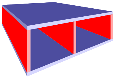
The system is still a stereo system, so to ensure the response is predictable, as well as to add structural integrity and bracing to the quite thin MDF, a partition to divide the two halves was added.
I'm aware that the design isn't optimal for the best sound quality - reasons why it is less than ideal is because the speakers won't be at ear level, the speakers are mounted behind the panel (so they'll be some wave-guided reflections) and the box is not optimally designed to fit the speaker response parameters. Normally you should use Theile-Small and a speaker box design program to design the box.
As this system is not designed to be Hi-Fi though, it's OK. It does what it needs to, which is to outperform monitor speakers / laptop speakers etc.
To improve the appearance, I planned to round off the side edges with a plane. This would cause a problem if the joins were mitred, so I just used straight edges throughout. After sanding and filling with wood filler and priming with a shellac primer, there should be no evidence of the joins.
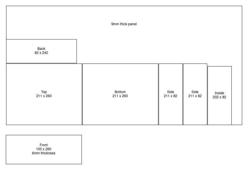
I figured the most obvious place where I wouldn't want any edges showing up would be the front panel. Therefore, this sits in front of the box sides and the size of the panel is easy to calculate as 260 × 100mm.
The top/bottom then sit in front of the two sides. This gives structure strength that would allow objects (i.e., the monitor) to be placed on top of the box. This will leave two speaker cavities of just over 2 litres each (2.016l), though in reality it's a fair bit less than this as the electronics, speakers and the plywood edging will eat into that volume.
For the sides, the depth needs to take off the thickness of the front panel, therefore: 220 − 9 = 211mm. The height needs to take of the thickness of the top and bottom panels, therefore: 100 − 9 − 9 = 82mm.
For the top/bottom panels - the depth would be the same 211mm, and the width would be the full 260mm. The final speaker depth actually turned out to be 217mm - 3mm less than planned because I swapped the front from 9mm MDF to 6mm MDF, but it's not a problem really!
The inside panel is 82mm × 199mm. 18mm is taken off the overall height to get to 82mm (same as the side panels). The depth would be 202mm, allowing for the front panel and the rear panel to recess inside the top/bottom/side panels.
The rear itself should be removable for servicing. This would be 242mm × 82mm to allow for it to sit inside the box.
When marking out, I considered the width of the cut. For a jigsaw metal blade I used, that's about 2mm, but to consider adding another millimetre or two because you can always sand it back if it's too big after, but if it's too small you can often not add material back on!
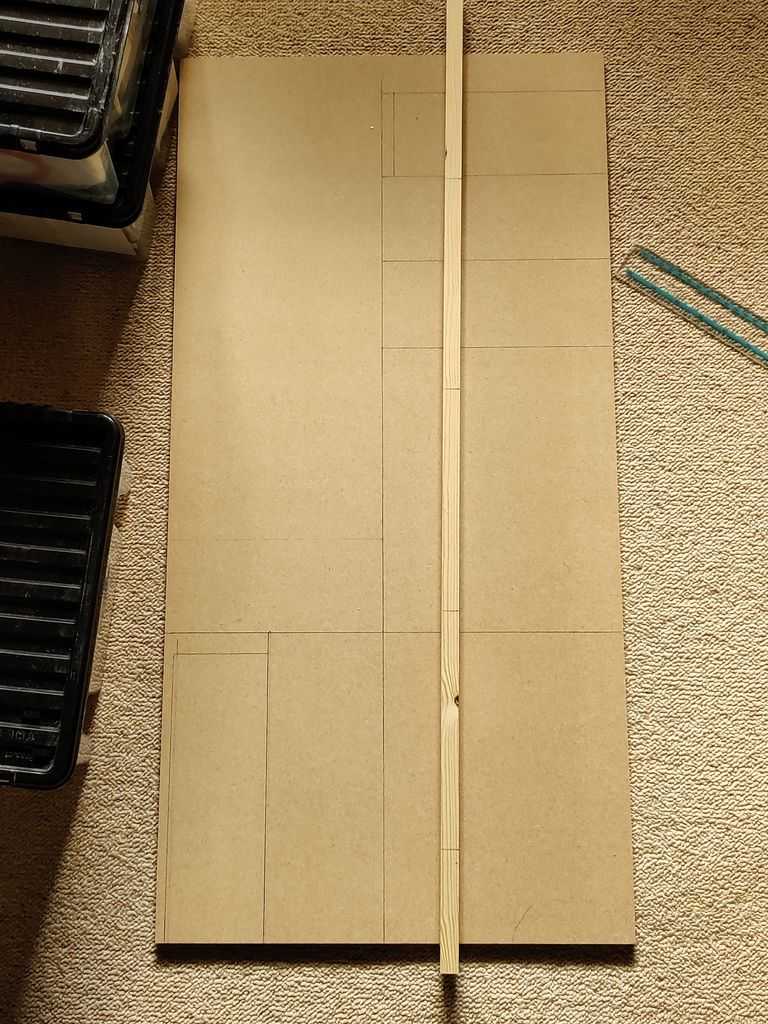
Above: Picture of MDF marked out. I included the front panel in my original cuts, but then changed my mind and got thinner MDF for the
front later
Cutting and drilling the sheets
MDF is quite easy to work with. There are no knots or grain to worry about so you can cut it without rigorous planning ahead.
Its disadvantages though are that it is very dusty. Because it is also quite dense, it does blunt blades and drill bits sooner than natural wood. It also tends to tear easily when cutting and especially drilling, so think about what side can be rougher when cutting/drilling. The side facing you will be the best side as the exit side will have tear out.
For cutting, I used a jigsaw and a slow speed and using a metal blade. This helps reduce the amount of dust chucked out and the tearing. As I needed to cut straight lines with a jigsaw, I went slow and steady, following a clearly marked line and gently blew the dust off as I went so it did not obscure the line.
I strongly advise cutting outdoors on a dry day. As I still live in a flat at the time of writing, I had to do it indoors, but I wore a face mask to reduce the dust I was breathing in. It's horrid dust, and even carcinogenic. Despite taking it slow, fine dust was still everywhere in the room after! The same advice applies to sanding and drilling.
An oblong hole in the back needed to be made for the amplifier to sit on the heatsink (which is mounted on the outside). To do this, I drilled two rough 10mm holes first, and then used the jigsaw to cut to the other two corners, straightening up after with the jigsaw and a file.
The two cuts for the speakers would be made with a hole saw. They could be done with a jigsaw too, but cutting a tight, perfectly circle 3 inch hole would be difficult, whereas the hole saw cuts a perfect circle.
Go slow with the hole saw and stop several times to allow it to cool down, otherwise it will start burning the MDF. Stopping allows you to check the depth of the cut around the circle too to see if it's uniform. If it's deeper on one side of the circle then the other, that means the drill is not held straight (at a perfect right angle to the wood in both axis).
The hole for the potentiometer was done with a flat (spur) 12mm wood drill bit, but not all the way through. This creates a 12mm recess for the nut since both the potentiometer thread is not long enough to fit through the 8mm MDF front, and this also allows the volume control knob to be mounted flush to the front after. Once the cut from the lip of these bits is deep enough, the hole made by the spur needs to be widened by drilling it with a standard 8mm drill bit.
The switch hole was also done with one of these flat drill bits, but this time all the way through the wood. These drill bits tend to cut rounder holes whereas standard large drill bits can end up making a hole that looks like a rounded triangle in thin material!
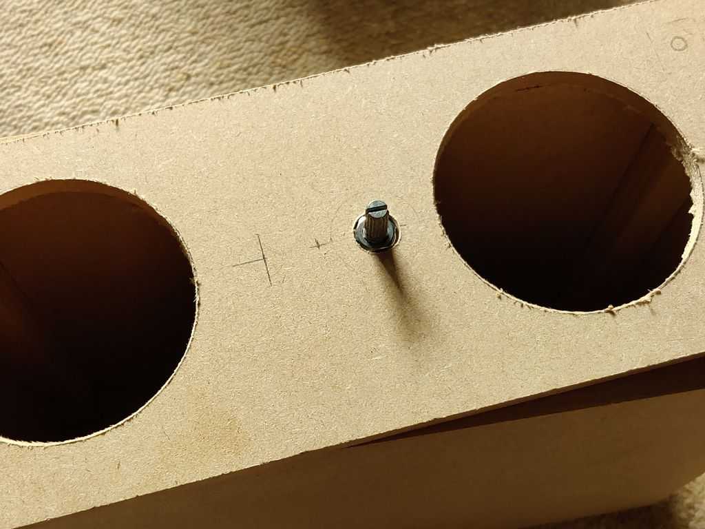
Above: Partially cut front panel showing speaker hole cut-outs and potentiometer cut-out with recessed mounting
The rest of the holes are done with standard drill bits - that's a hole for the LED, and holes in the back for the power socket, phono jacks and screws.
Assembling
Once I had all the pieces, including any holes cut and drilled, the next stage was to assemble the pieces in to a box.
I didn't want to have nails or screws showing on the outside which would make the surface finishing harder, so I used plywood edging 15mm × 15mm in the corners to give it strength.
I used some short 20mm length screws which were the ideal length for screwing through the plywood and into the MDF. I did test it on some spare MDF first to ensure no bump was formed on the surface of the MDF the screw was behind to make sure this wouldn't be an issue. I both the test and real build I drilled a 1.5mm pilot hole for the wood screw to enter.
After an initial test screwing it together (without applying too much force), I then disassembled again and used Evostick wood glue on the entire length of the sides and screwed it back together. Evostick wood glue is pretty good and adds the necessary strength to the box that screws alone would not provide.
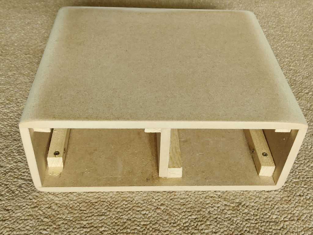
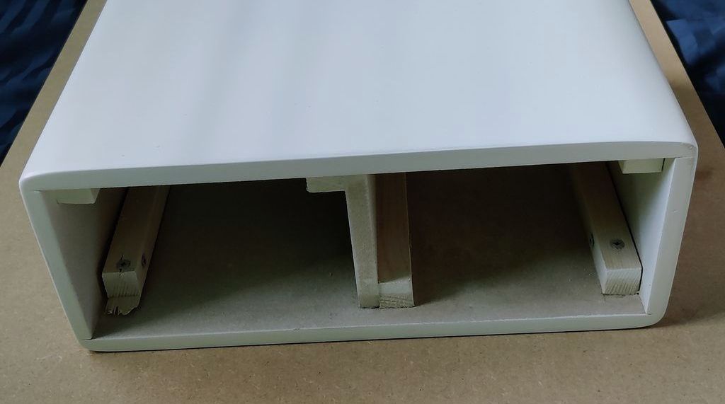
Above: View of bare speaker box from the back (after rounding/sanding) - showing the assembled bracing
Rounded corners and Sanding
Like all DIY assemblies, the box wasn't completely perfect. I actually intended to assemble it with a bit of overhang so that I could knock the excess back with sandpaper.
To make it perfectly square, I took some rough P80 sandpaper and placed it in a sanding block and hand sanded down all sides until the box was square.
To make the edges round, a router would be ideal, but I opted for a cheaper option and brought a wood chamfer edging plane that can create either flat 45° angles, or rounded angles up to ¼".
The tool I don't recommend as I found it cheap in quality and not easy to use. The bits were also not sharp. I got it to do what I needed eventually by slowing adjusting the rounded bit further out from the tool each time, but I did end up pushing it out too far and going deeper into the wood than I wanted to. This needed excessive sanding to correct, and I ended up making corners that represent a ¼ of an oval instead of a circle! Looks OK and a little unique in practice though.
After rough sanding, I then went to lighter sand paper - P150 and then P220 if I remember correctly.
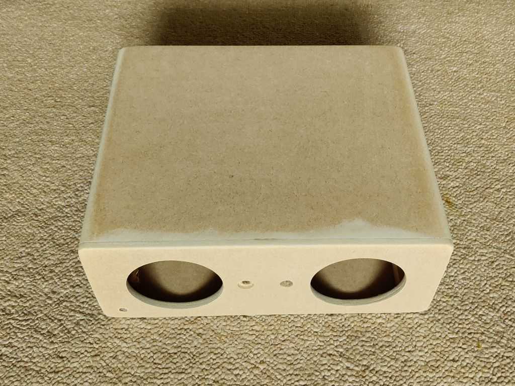
Above: View of bare speaker box from the top front
There were some gaps where the wood was not cut and sanded perfectly straight, so I used Ronseal Wood Filler to applying in any gaps and sanded it back after it dried.
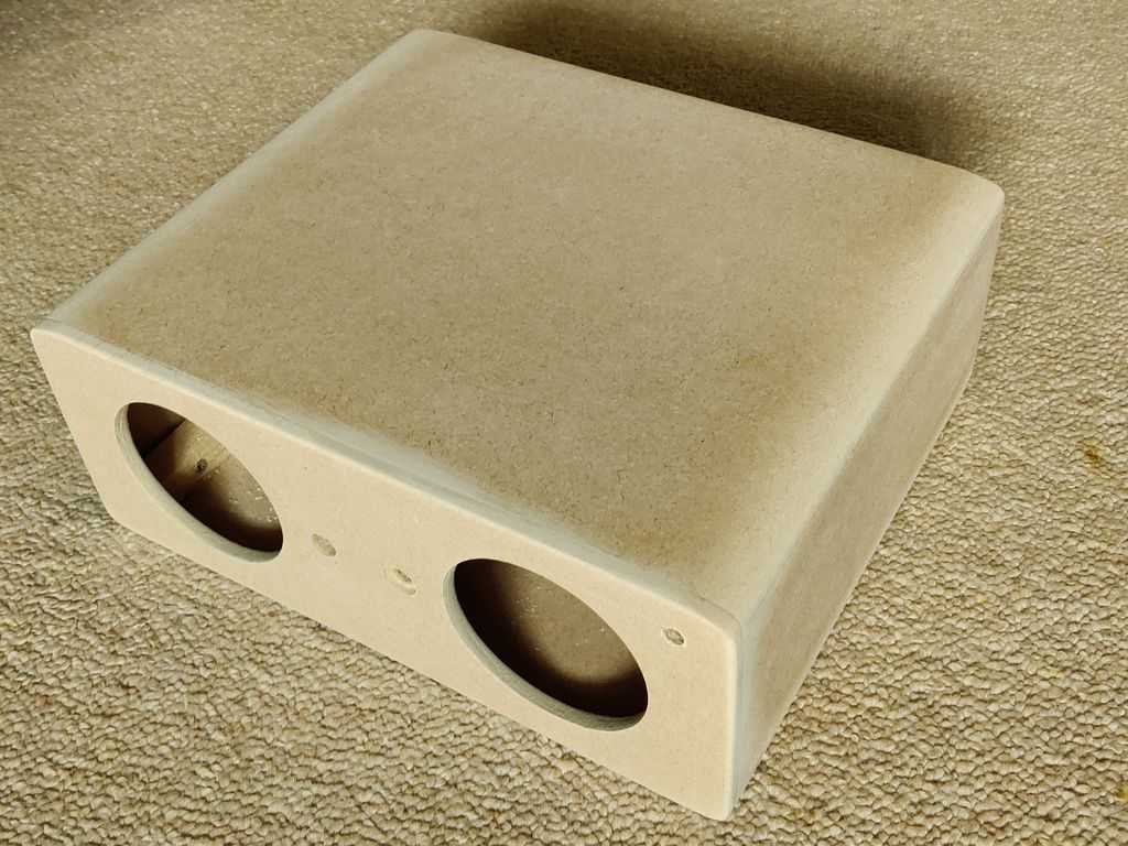
Above: View of bare speaker box from the top side front
Surface finish
Most boxes I've built previously years ago I finished off by wrapping it with sticky back plastic. Even this was done for my subwoofer build.
For this build though I wanted to make it look nicer and I ended up spending far too many hours than I would have liked to try and make a perfect surface. I must say I got pretty close and unless you look really closely, it looks pretty much professional.
As mentioned above, I sanded back the MDF smooth before doing any work on the finish. In hindsight I did not do this pre-sanding step well enough which cost me time and extra cost in primer and paint to later correct.
Assuming that's done well though, the wood should be dust free by wiping with a dry cloth. The primer can then be applied.
As it's a small build, I didn't want to spend much on primer. Shellac primer is great, but it has a short shelf life so I didn't want to store excess that would end up bad before I could use it. So, I went for the small spray can of Zinsser B-I-N.
In a larger build, it would make more sense to get a paint can of Zinsser 123 or Zinsser B-I-N though and paint it on and sand it back after.
The spray can version is a bit different to use but works quite well. Instructions say to apply in bursts, so I did that until I got complete coverage of the MDF. Then I sanded it back, applied again, repeat, repeat, repeat...!
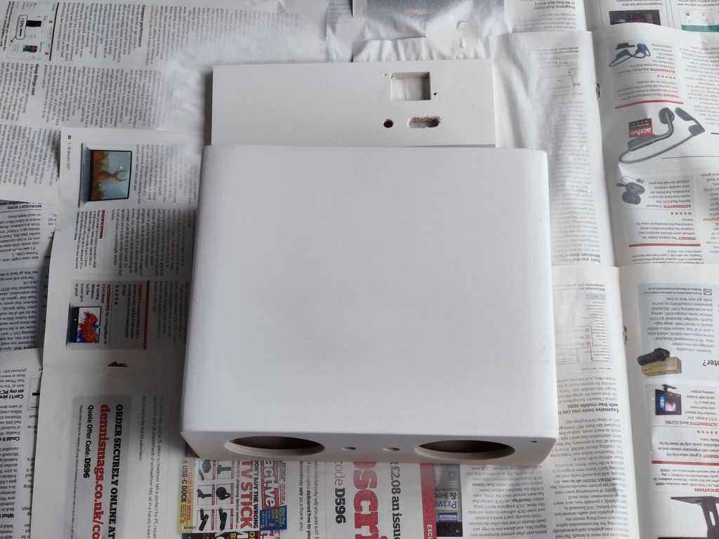
Above: Initial primer application
Had I done my initial sanding before applying the primer better, I wouldn't have had issues with sanding the primer back down to the MDF in places after applying it, and the job would have been quicker. Still, shellac is great and allowed me to create a completely smooth surface ready for painting.
After each application of Zinsser BIN, I sanded back with 180 and then 250 grit dry paper. BIN dries really quick and I lightly sanded it after just 10 to 15 minutes (it was a warm day though) and re-coated after 30 minutes.
The 400ml can pretty much ran out before I was done on such a small speaker, and there were some areas that were not perfectly smooth either and I hoped the paint would correct that - which it did, but not easily!
Above: After primer application - top front
Above: After primer application - rear view
For painting, I wanted a white gloss finish. I used Plasticote Gloss White spray paint, as it's well reviewed and pretty cheap. Again, it comes in a 400ml can. It's pretty good stuff, but because of the surface issues, I needed to use quite a lot. For a larger speaker, you'd definitely need another can, two or three! Note: As I write this, the white is starting to yellow, so I don't recommend this, at least with the primer and I'll need to redo it someday :-(
The technique is to evenly apply the paint in many thin coats, with an hour drying between each. So, ensure you have a whole day! It didn't look very gloss though so on the last coat I sprayed a little slower which gave it a gloss looking with sparkles!
After spraying, later in the evening I sanded the paint smooth, but I did this three or four times and then had to apply more paint the next day as I sanded too much off looking for perfection and the primer ended up flashing through. Don't make this mistake! Better surface prep both before the primer and after would have avoided this.
On the final sand, I used 1000 to 2000 grit paper, with soapy wet water (Fairy liquid mixed with water). The wet and dry abrasive paper I brought holds up well when wet and gives a really smooth surface.
Once I was happy with the surface, to apply more protection and gloss, a clear lacquer was to be applied. I used Hycote clear spray lacquer as it's well reviewed.
Sadly, it was a too hot day really, but with wind, and in one area on the top, too much lacquer was applied, and it bubbled. This ruined the job and I ended up having to sand it all off, which also ended up taking the paint off in areas too and in one area I had almost gone back to the MDF itself.
I knew the lacquer was good though as on the sides the finish I was very happy with. Another can of paint plus sanding was done (fortunately enough primer was left for me to get away with it!) and attempt two a few days later of the lacquer succeeded.
The lacquer was lightly wet sanded with 1000 and then 2000 grit paper to have a smooth surface.
Because of my mistakes especially, this was a painful process. Lessons learned though, and I'd be more comfortable doing it again and not spending weeks. You will need to plan at least three days though for priming, painting and applying the lacquer. Another lesson is don't underestimate the amount of over-spray. It drifts far and balcony furniture is potentially ruined now. It looks dusty, but white dusty, and in other areas it's clean so I know it was over-spray!
Overall, I'm happy though - the result looks really good and much better than sticky back plastic.
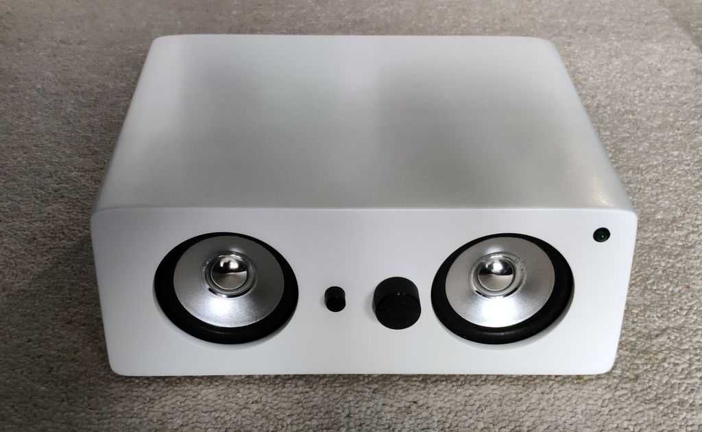
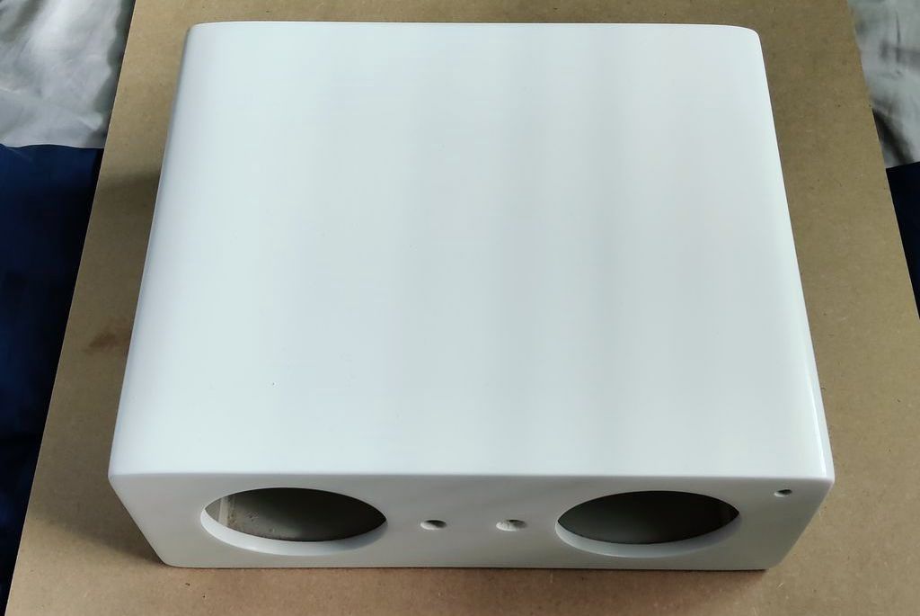
Above: Completed view - front top
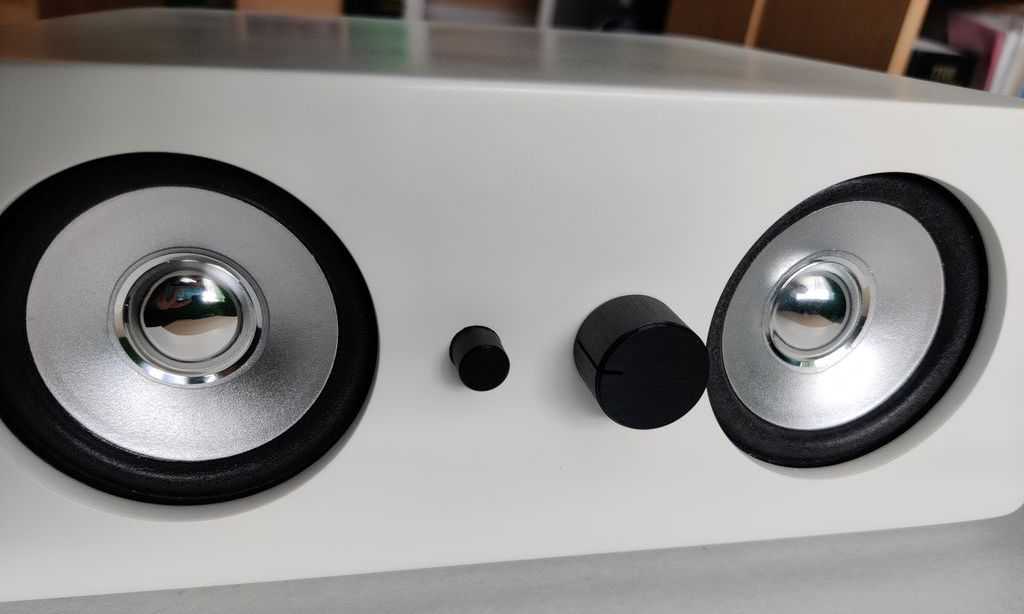
Above: Completed view - front
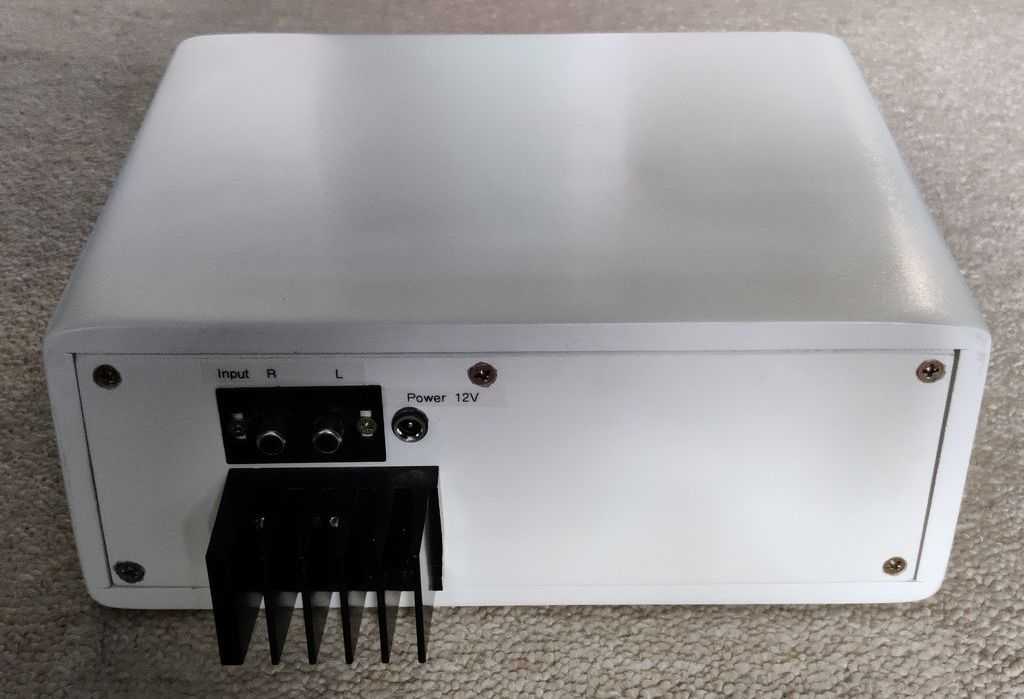
Above: Completed view - rear
The electronics
The electronics were to be kept simple but give good performance. I've built quite a few amplifiers that I haven't used yet, but I settled on the TDA7297 as it's a very popular, but cheap, amplifier with pretty good performance.
The speakers have an impedance of 4 ohms and the power supply would be 12V (using anything higher is pushing the chip a bit!). Output power of the TDA7297 is a bit unknown into 4 ohms, but it should reach around 15W per channel. The speakers are actually just 10W, but they'll survive!
The TDA7297 amplifier I used is the exact one I featured in my TDA7297 article, built on a custom PCB. The only change I made is I swapped the 10µF capacitor C4 with 100µF for a longer power on mute time.
On my TDA7297 page, there is a section named 'Making a system', and that scheme is pretty much what was used here, except I added a bass boost circuit - the single supply non-inverting version. This adds some warmth to the sound and restores bass response lost by the small speakers and the non-ported cabinet.
Below is a high level schematic / diagram of how the electronics fit together. Nothing fancy - just a simple and functional system!
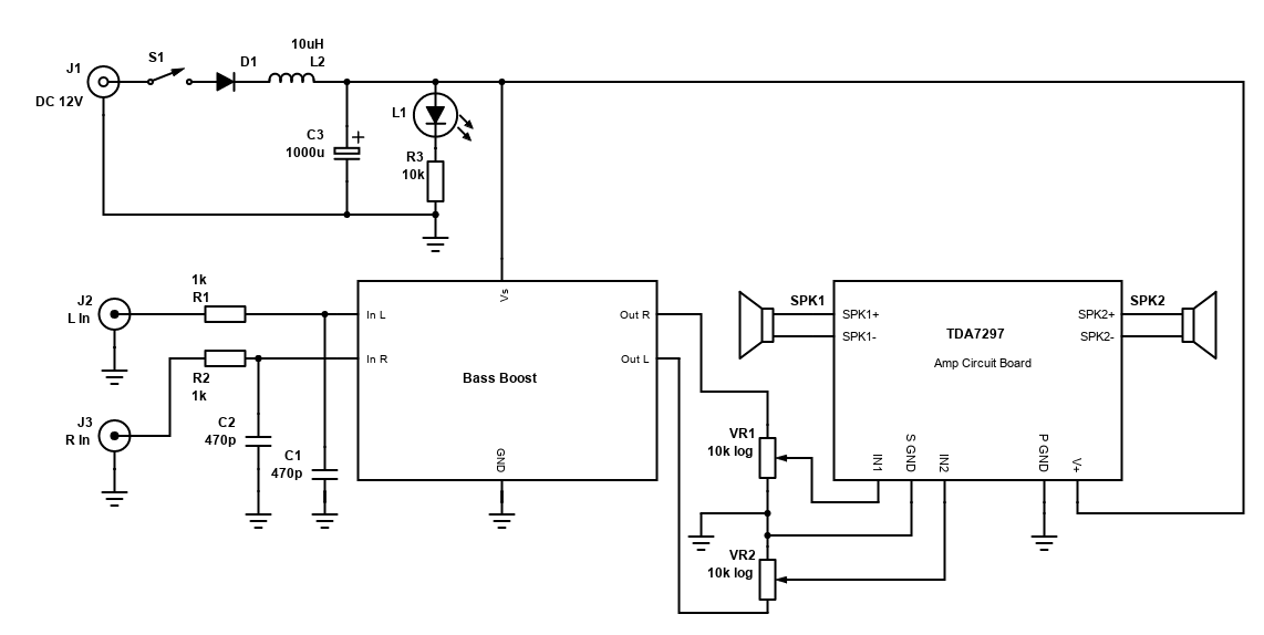
The bass boost circuit has DC blocking capacitors on its output, and the TDA7297 has DC blocking capacitors on its input, so the volume control (a dual-gang 10k logarithmic potentiometer) can sit in between them effectively and hopefully not go noisy after time because it is free of DC.
I used a couple of simple stripboard circuits for building a low pass filter (for noise filtering) and input star grounding, and another circuit board for the PSU filtering (inductor and capacitor), including LED current limiting resistor. These simple boards include headers so I can easily use Dupont female connectors to hook up the system.
To reduce interference, I used some (really old!) 470pF capacitors after the 1k input resistors. This forms a low pass filter to filter out frequencies above 330kHz and will help filter out GSM noise.
Some pictures of the electronics mounted on the back panel of the box are below. It's not particularly neat and I think I would have found it a bit easier if the bass boost was on the same side as the rest of the electronics so not as many wires needed to cross the two speaker box cavities.
You can see I cut groves into the back panel so that the wires can pass through the two cavities and kept them there with glue from a glue gun.
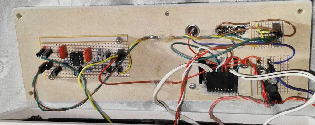
Above: Inside view of the rear. Bass Boost circuit on the left. On the right, clockwise - power input socket, L/R phono inputs, input filter/star
ground PCB, PSU filter PCB, TDA7297 amplifier.
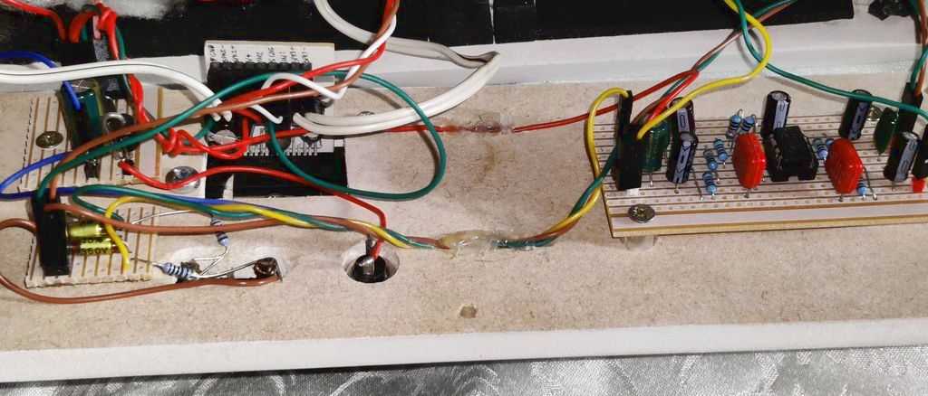
Above: Alternative view.
Above: Closer view of input circuit, PSU circuit and TDA7297 amplifier.
Conclusion
I don't use it myself, it's for my wife. She is happy with it though and uses it every week day, mainly for watching videos, listening to podcasts and joining Zoom calls. Having, of course, listened to it myself post-build, it's pretty good and whilst not exceptional quality for its size, it meets its purpose of outperforming the monitor speakers or any laptop speakers. I'd say it also outperforms cheap pre-made speakers, or mono Bluetooth speakers.
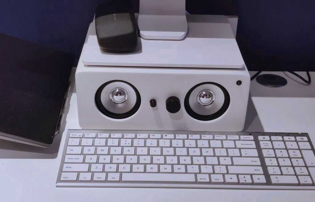
The convenience of it fitting below the monitor is its appeal for her, and actually her own idea. This means it occupies no extra desk space, raises the monitor to an ideal height and is easily switched on/off and volume adjusted by having those controls right in front of the keyboard.
For me, building it was interesting. The amplifier I already had and wrote up in 2020. The bass boost used my previous schematic written up earlier, but this time I built it on stripboard and wrote up the results on that article for anyone's interest. The real interest though was building the box and finishing it off. Although I've cut and made boxes many years ago when I lived with parents, I've never done it since so it was nice to do that again. I've also never finished a cabinet in a smooth gloss finish, and whilst it took absolutely ages, the result is pretty good!