
TDA2030 Amplifier Project
2xTDA2030 - 12W stereo amplifier project
This amplifier started off as a small project as I had one of the TDA2030 amplifier boards spare after adding the TDA1514 to my TDA Surround Sound Amp back in 2003 which meant I had a TDA2030 spare. I also had a second-hand but high quality isolated 30VA 2x12VAC toroidal transformer made by Avel-Lindberg (who were UK based in South-Ockendon, but no more). Finally, I also had a low cost case from Maplin which I originally housed just a simple surround sound decoder. Adding another TDA2030 would be a quick and simple project to make a good quality stereo amplifier for my PC.
The TDA2030 is a great amplifier, with full information featured in my article here.
So really, this is an old project - something I did in 2004, according to the photos. It did sit mainly unused though until around 2009 when I moved in to my first home (a two bed flat) where it found use in the second bedroom for PC and radio use. I used it right up until early 2020 when my LM3886 DAB amplifier replaced it.
The amplifier has evolved over the years. It was first just a stereo TDA2030 amplifier with no preamp, just a volume control, power LED and power switch, as per this original photo:
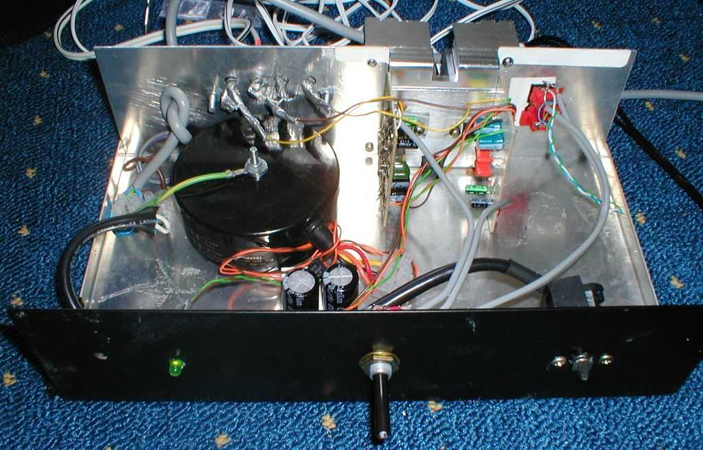
As can be seen - pretty simple. A mains cable (without socket at the time), leading to a switch from an old AT PC, to a 30VA 12V AC transformer, followed by a very simple unregulated linear PSU formed of a 1.5A bridge rectifier and two 4,700uF capacitors makes up the power supply. A resistor and LED are also connected to that.
The input section was two phono sockets from an old, discarded Sky TV box going to a dual gang log potentiometer and then direct to the TDA2030 amplifiers.
Stereo spring clips were for connecting the speakers, and that's it - a very simple build. Here are a couple more pictures from 2004:
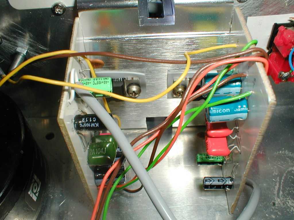
Above: The amplifiers are mounted on an old AMD Athlon K6 heatsink. The amplifier with the orange capacitors was my original one.
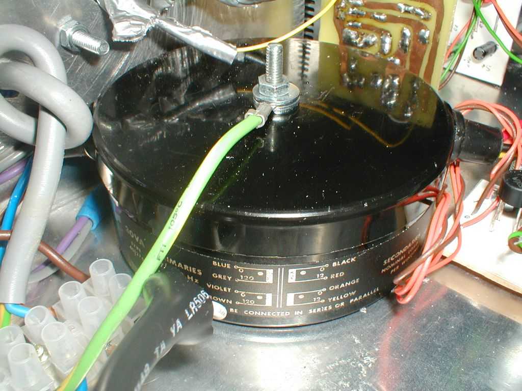
Above: The Avel-Lindberg 30Va transformer. I can't remember how I obtained it - was either salvaged or eBay! Note that this earth connection is NOT
properly safe - an issue I have now resolved!
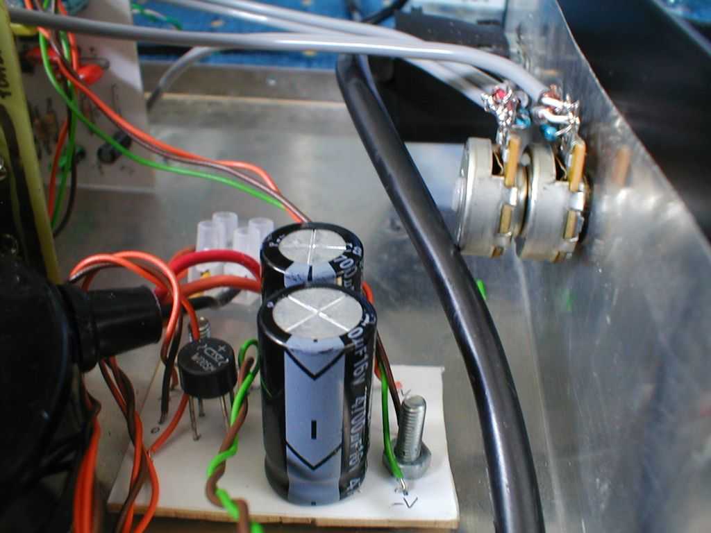
Above: PSU and volume control.
The transformer, after being rectified, will give about +/-16 to +/-17V DC which has the potential to allow those TDA2030 to hit almost 12W into 8 ohms, however, the 30VA transformer won't really allow them to. It's just about enough for music power though, and enough for light listening which is all I ever intended this amplifier for anyway. Really you should pick 50VA for 8 ohms, and bigger still (80VA+) for driving 4 ohm speakers!
Today / Upgrades
After it was built and I moved back from university and took my bigger amps with me back to my parents, this amplifier was put away between 2006 until I moved out to my first home in 2009 and it became amplifier number 3 in the second bedroom where I had the desktop PC. It was mainly for PC games and music.
It was apparent that it needed upgrades though and between 2010 and 2015 it received:
- Tone controls (bass and treble), which was a revision 1 board (with mistakes) from my TDA1514 amplifier that I corrected and used in this build. Based on the Baxandall Tone Controls featured at ESP
- This needed a +/-12V linear regulated PSU, using 7812/7912 regulators
- I also added a balanced line output and phase switch for connecting my subwoofer
- For radio listening though whilst working, I didn't like to use the subwoofer, so I added a bass boost circuit and switch
- I replaced the single stereo phono connection with a dual connection, and added a 3.5mm front facing input, and 3-way selector switch - this way I could use either the DAB radio, PC or plug my phone in the front (back in the days when phones had 3.5mm outputs!)
- I also added a 5V regulator for powering the Chromecast audio, which ended up being permanently plugged into that front facing 3.5mm input
The layout was also altered so that the mains wires and PSU is entirely on the left hand side of the case, away from the audio circuits.
I wrapped the front with a wood effect sticky black plastic, which gave it a bit of a different look. The power switch was replaced by a rotary one as those have a satisfying feel. Volume potentiometer was also replaced as it became noisy, and audio cables replaced with twisted pairs and ground layout redone to ensure the amplifier is quiet, without any hum.
It's a messy layout by my own standards - all point-to-point soldered. As mentioned though, it's quiet, with hardly any hum noise so I don't have a much to gain from a rewire.
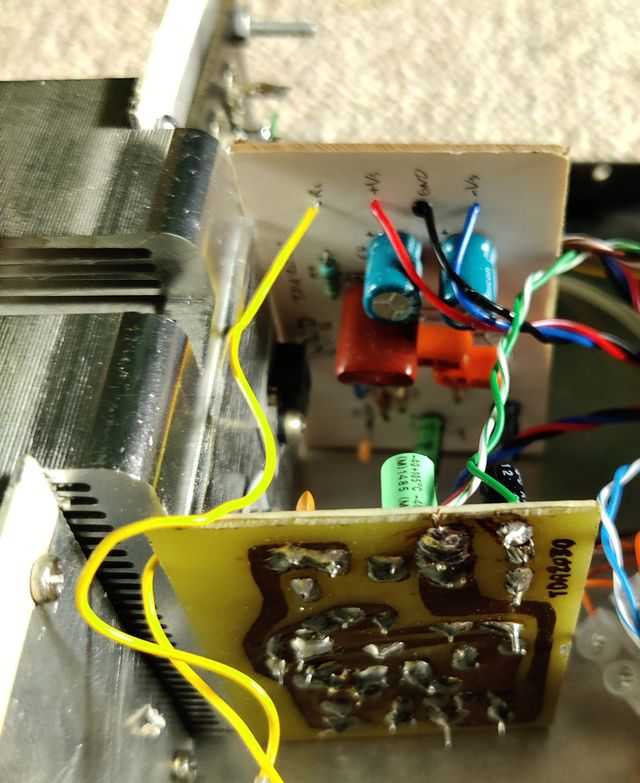
Below is a diagram of the layout, including ground layout. Ground layout is a bit of a dark art, and here I used a combination of star grounding for the power grounds and speaker grounds, but audio ground (which is also the audio return path) follows the signal using twisted pairs from old network cable. Although this seems to be creating loops, because the power and speaker ground currents should follow the more direct path to the PSU, the layout works well.
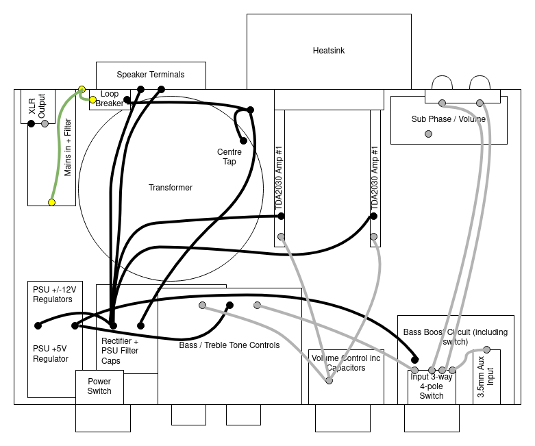
The power grounds are all stiff single core wire, soldered to pins on the PCBs directly. The audio grounds are thin multicore twisted pair from network cable, again soldered at each end to pins on the PCBs.
The unit is earthed via the mains earth which connects to both the chassis and a loop breaker (formed of two diodes, a 10 ohm resistor and a 100nF X2 capacitor). This is to avoid any hum inducing earth loops with external equipment. The loop breaker then connects to the centre tap of the transformer, which is connected to the power ground star (at the PSU PCB named "Rectifier + PSU Filter Caps"). This ground does not connect to the chassis directly (except through the 3.5mm front input jack, but this ground is switched).
The main PSU board forms a power ground that the two TDA2030 amplifiers connect to, and the speaker returns connect to. This ground is also connected to the regulated PSU PCB and another star ground is used there for connecting the low power op-amp based PCBs - Tone Controls, Bass Boost and Subwoofer Phase and Balanced output boards (grounds for these are not shown in the diagram as they are optional, and I've not used them in years so unsure how well they perform!).
The input ground wires (shown in grey), also known as signal return, are wired from each PCB point-to-point, following the signal path. The wires from the input selector switch to the tone control board, and also the wires from tone control to volume control board are actually two pairs of twisted ground wires (for stereo left and right). The remaining grey wires are just single pairs. Ground for the 3.5mm input shares a common ground wire for left/right as normal for these types of inputs.
A key feature is the input selector switch. This is a 4-pole 3-way rotary switch, and I used the three of the poles to switch the left and right audio channels, but also the ground too. As the 3.5mm input jack on the front is not isolated from the case/chassis, it bypasses the loop breaker. That's OK for devices I connect to the 3.5mm input because they are usually battery powered portable devices (like a smartphone) and would not create an external ground loop. As the ground is switched when I select another input source from the isolated phono sockets at the back, the ground is no longer shorted to the case directly and goes through the loop breaker - avoiding any hum. See ESP article referenced below for more information on earth loops and loop breakers.
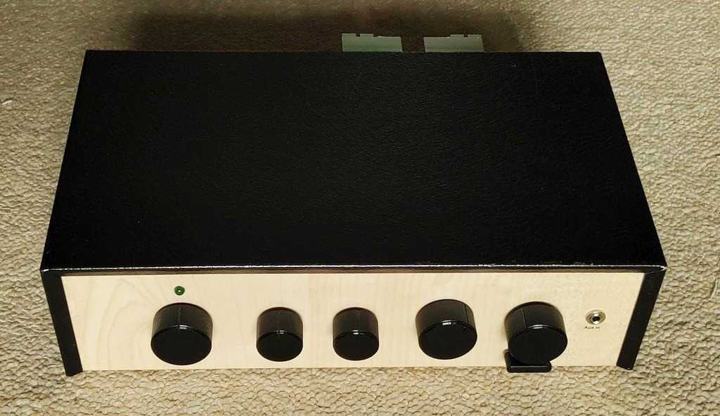
Above: Top/front view with case cover on.
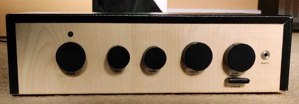
Above: Front view. From right to left - power switch (rotary) with original green LED above it, Bass, Treble, Volume, Input (rotary again), Bass Boost
Switch below that, and 3.5mm Auxiliary input furthest right.
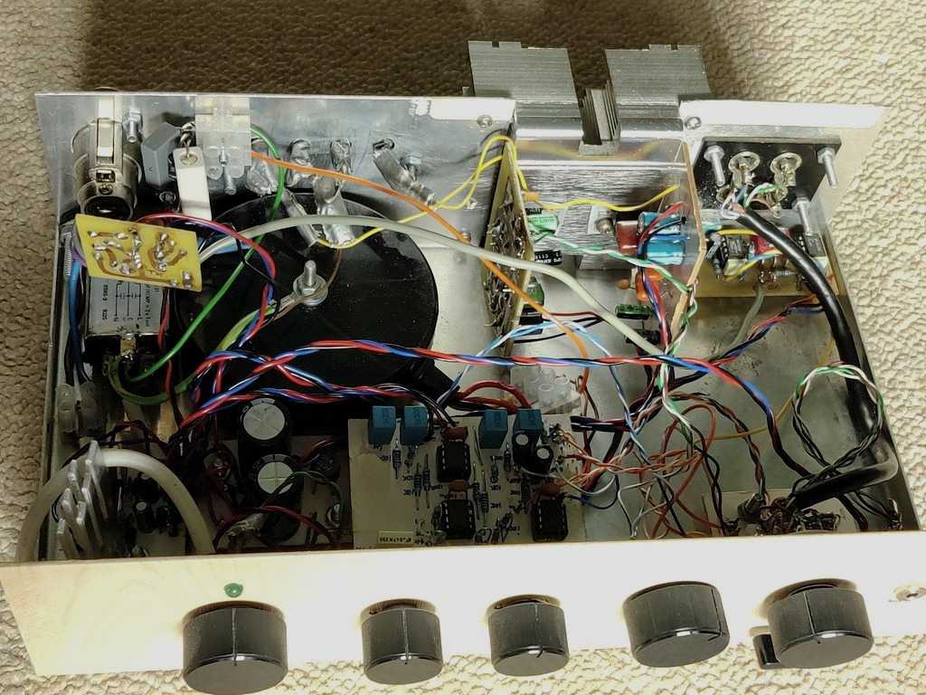
Above: Top/front view with case cover off - top left clockwise: Balanced line subwoofer output, with filtered IEC mains socket below it, 30VA
transformer with earth loop breaker and speaker connections above it, TDA2030 amplifiers, phono inputs with subwoofer volume and phase selection below
them, bass boost circuit (bottom right), volume control, tone control board, PSU (unregulated and regulated), mains power switch, 5V PSU.
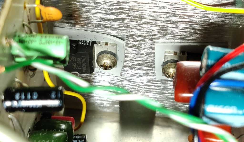
Above: Close view of the TDA2030. These are originals from Maplin 2002/2004.
Above: Another view of TDA2030 amplifier boards. This board layout is as per the datasheet and schematic, all described in my
LM1875 / TDA2030 article.
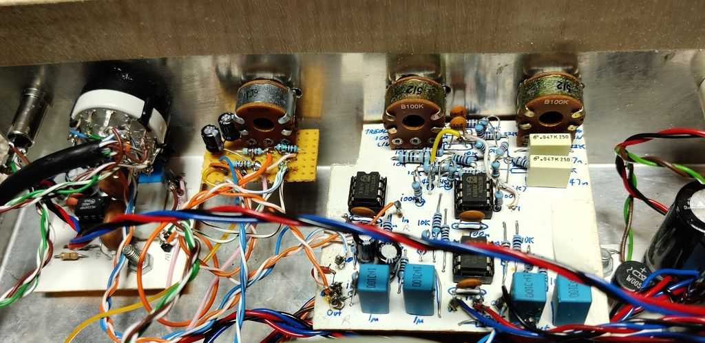
Above: From top left: Input selector switch, with bass boost circuit below that, volume control with loading resistors
(see ESP Project 01) and Baxandall Tone Controls.
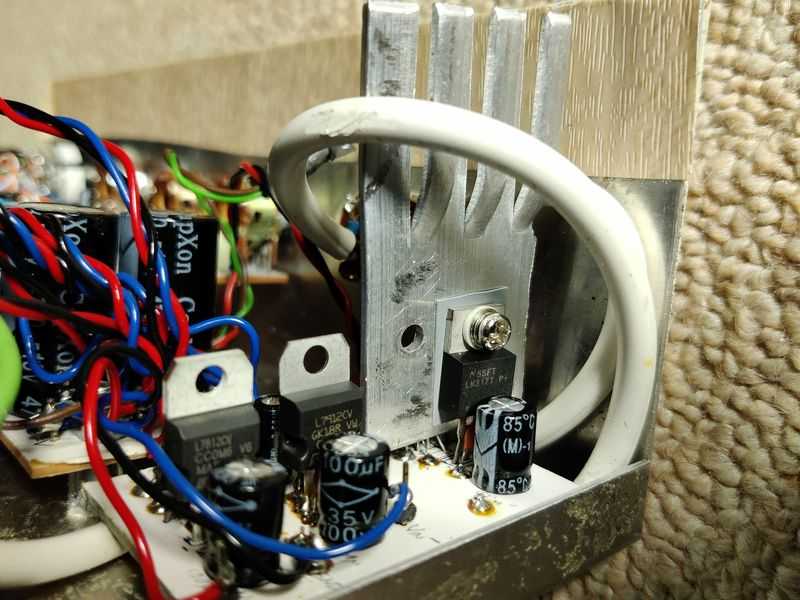
Above: Regulated PSU based on 7812, 7912 for +/-12V needed for the opamps in the tone control, bass boost and subwoofer balance output,
similar to ESP project 05 mini. Also includes a 7805 +5V regulator, on a heatsink since the voltage
drop is high (and therefore efficiency is poor).
Sadly, the amp now lays dormant. When my wife and I move into a house though with more rooms, this would become useful again, at least I hope so because it's actually really good quality - almost Hi-Fi I'd say, just lacks power!
References and more reading:
ESP - How to Wire a Power Supply
ESP - Earthing Your Hi-Fi - Tricks and Techniques
ESP - Project 04 - Power Supply For Amplifiers
ESP - Project 05-Mini - Power Supply for Preamplifiers
ESP - Project 01 - Better Volume Control
ESP - Designing With Opamps - Part 2 - Baxandall Tone Controls
TDA2030 Datasheet