
TPA3122D2 / TPA3125D2 DIY Guide - 15W/10W Stereo Single Chip Class D DIP Power Amplifier
The TPA3122D2 (TPA3122D2N) and TPA3125D2 (TPA3125D2N) are reasonably simple to build and popular Class D amplifier chips that are still readily available as of October 2024. They allow you to easily produce a high-performance stereo amplifier with high power efficiency.
Recommended Experience : Intermediate, knowledge of amplifiers, inductors, circuit layout
Updated October 2024 - improved PCB layout and added measurements and capacitor comments.
TPA3122D2 and TPA3125D2 application
Quick facts TPA3122D2
- Power output: 15W + 15W into 8 ohms at 10% 1kHz distortion with power supply 28V
- Power output: 12W + 12W into 8 ohms at 1% 1kHz distortion with power supply 28V
- Power output: 8W + 8W into 8 ohms at 1% 1kHz distortion with power supply 24V
- Power output: 5W + 5W into 4 ohms at 10% 1kHz distortion with power supply 12V
- Power output: 4W + 4W into 4 ohms at 1% 1kHz distortion with power supply 12V
- Power output: 3W + 3W into 8 ohms at 10% 1kHz distortion with power supply 12V
- Power output: 2W + 2W into 8 ohms at 1% 1kHz distortion with power supply 12V
- Gain: 20dB / 26dB / 32dB / 36dB choice of 4 fixed gains
- Power supply: 10V to 30V single supply
- Class D
- Datasheet available here
Quick facts TPA3125D2
- Power output: 10W + 10W into 8 ohms at 10% 1kHz distortion with power supply 24V
- Power output: 8W + 8W into 8 ohms at 1% 1kHz distortion with power supply 24V
- Power output: 5W + 5W into 4 ohms at 10% 1kHz distortion with power supply 12V
- Power output: 4W + 4W into 4 ohms at 1% 1kHz distortion with power supply 12V
- Power output: 3W + 3W into 8 ohms at 10% 1kHz distortion with power supply 12V
- Power output: 2W + 2W into 8 ohms at 1% 1kHz distortion with power supply 12V
- Gain: 20dB / 26dB / 32dB / 36dB choice of 4 fixed gains
- Power supply: 10V to 26V single supply
- Class D
- Datasheet available here
Guide
The TPA3122D2 is a simple to build stereo / dual amplifier that can deliver a pretty decent amount of power into 8 ohm speakers from a single rail power supply.
The TPA3125D2 is basically the same, except it is less capable with a maximum supply voltage of 26V, limiting the single ended power output (at 10% THD) into 8 ohms at 10W. It might be a little cheaper at your supplier, but check.
The guide below and my tests are for the TPA3122D2 specifically, but the TPA3125D2 has the exact same pinout and circuit, and therefore, advice.
The application is intended for Televisions, but has a wide range of possibilities:
- It is a capable amp for a stereo system (i.e. a homemade or upgraded midi system or 'ghetto-Blaster')
- Decent quality PC speakers
- Stereo or Bi-amplified Bluetooth speaker
- A pair could make a Bi-amplified sound system
- The chip could be bridged to make a powerful mono amplifier into an 8 ohm speaker, such as a subwoofer
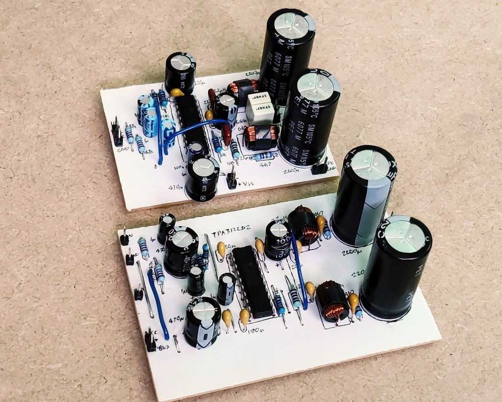
Above: View of my TPA3122D2 custom PCB board, and the stripboard layout for size comparison
The TPA3122D2 / TPA3125D2 are class D amplifiers, and one of the very few we can easily DIY build as it comes in a DIP package, hence I was interested to buy one and see how it performs!
This amplifier is based on the typical application in the Texas Instruments datasheet. The performance from this circuit is good. The sheet contains data for typical noise and distortion statistics. Whilst I can't confirm these statistics, the output from this amplifier sounds fine.
A Class D amplifier such as the TPA3122D2 does not necessarily mean you'll get more power output for the same voltage, but its efficiency means you'll get more power output for the power supplied - the product of voltage and current (amps). For example, on 12V you won't get more than 2W at 8 ohms or 4W into 4 ohms. That's the same as a simpler class AB chip such as the STA540 in single ended mode. Bridging is the same, allowing 8W into 8 ohms, again the same as the STA540 bridged. Note that the TPA3122D2 cannot drive 4 ohm speakers in bridged mode. This takes it out of car applications.
Being Class D does mean it is efficient though (typically 80% efficient), so where the TPA3122D2 or TPA3125D2 will shine is in applications where heat removal is a problem (such as in the back of a flat screen TV), or the power supply is smaller. Neither chip needs a heatsink either, though a small one is recommended to prolong its life. Any competing Class AB amplifier (such as the STA540) will need a heatsink, as the efficiency is never better than 70%, and typically will be less than 50%.
Due to the amplifier's efficiency, it could also be useful in 'always on' applications, such as ambient music etc. The efficiency means that over a prolonged period of time it'll save some electricity over class AB chips. Efficiency is also good where more power is required, such as subwoofer amplifiers since low frequencies require a lot more energy to reproduce.
As it needs high voltages though, it's perhaps not so suitable for battery operated / portable applications. Whilst you could buck boost battery voltages to 20 to 30V (26V for TPA3125D2) for a reasonable power output, this would increase the amount of circuit boards needed to build such a system and give additional challenges such as noise. Pre-built bridged class D amplifier modules such as the PAM8403 or the PAM8610 are probably more suitable, or a bridged class AB design like the TDA7266, or STA540 if the battery voltage is above 8V.
Circuit
The TPA3122D2 / TPA3125D2 datasheets gives us a good circuit example to build a working amplifier. There's a couple of notes though:
- The single ended stereo version will need different output filter inductor/capacitors depending on the speaker impedance
- The BTL application shows how the speaker is wired, but expects you to provide it an inverted signal
- The gain can have four different configurations on the GAIN0 and GAIN1 pins
Single ended application
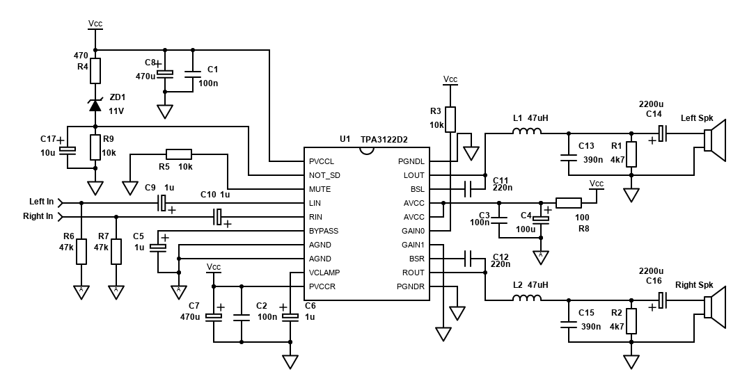
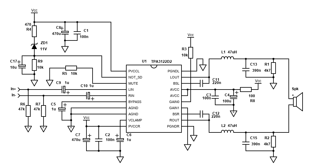
The circuit is basically as per the datasheet; however, I have added 47k input resistors R6 and R7. They prevent popping noises if you connect phono / 3.5mm inputs etc. whilst the amplifier is on, and also improve stability when connecting certain sources, such as mp3 players, smartphones etc. You can leave them out, or optionally install them on the sockets directly.
I've also isolated the AVCC pins from the power supply slightly with a 100 ohm resistor, and a larger 100u capacitor (C4) vs 10u suggested. This should improve distortion performance as it adds some filtering of any switching noise on the power rails. This modification is thanks to this HiFiDuino guide and one I recommend.
The output capacitors C14 and C16 have also been increased to 2200µF. This improves bass response, however 1000µF is still fine for 8 ohm speakers, and you can go lower if the speakers are not capable of reproducing these bass frequencies anyway. The calculation for the cut-off frequency is 1 / (2; * π * C * Z), so for an 8 ohm speaker, 1000µF capacitor (which is 0.001F) that's 1 / (2 * π * 0.001 * 8) giving 18.3Hz (at -3dB).
Finally, I've added some control components on the shutdown pin. C17 with R4 gives a startup time delay, and ZD1 with R9 shuts the amplifier down when the power supply voltage is less than 11V (Zener voltage can be varied for your power source). These components are detailed further below.
There is a difference between analogue and power grounds. In my redrawn schematic, the components going to analogue ground are shown with an 'A' in the ground net. The ground nets that are not labelled are power ground. The power and analogue grounds should connect only at a single point, next to (or underneath) the chip.
PCB
The best performance can be obtained by building a proper PCB, especially a dual sided one with a ground plane. My PCB Building guide has information on how you can draw and etch a custom PCBs.
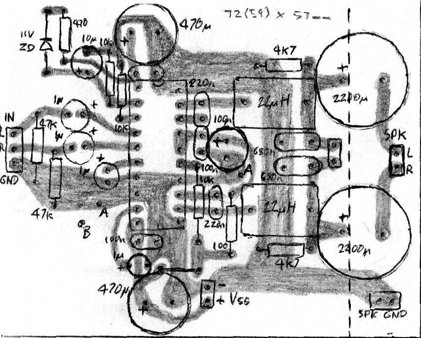
This is my hand drawn style, viewed from the top. This can simply be reversed and drawn as a copy onto single sided copper board. The DPI of this image should print to the exact size you need, which is 72mm x 57mm. It's single sided for simplicity, but I've tested it, and it is stable, with no hum.
The layout leaves plenty of room for large output capacitors. As it's all I had available, I installed 4,700µF capacitors which have a large diameter. If you have smaller capacitors though, you could reduce the board size. If you are building a bridged TPA3122D2 / TPA3125D2 amplifier, the board can be shortened to a length of 59mm, where the dotted line is shown.
Check the size of the 100µF and 470µF capacitors you are using. My board does not leave lots of room and larger diameter capacitors (which may be needed for voltages up to 30V) may be a struggle to fit.
Another point on this layout is it is customised to fit my Class D inductors. Your inductors are highly likely to be a different size, and the layout may need to be adjusted.
As a final note: the ground track for the 100nF and 100µF capacitors at the AVCC is reached via the GAIN1 pin (which is pulled low for 26dB gain). If you want a different gain, you will need to connect this ground through either both pins, or GAIN0 instead, or if you want a full 36dB gain, then a jumper to this ground track to the rest of the analogue ground will needed instead.
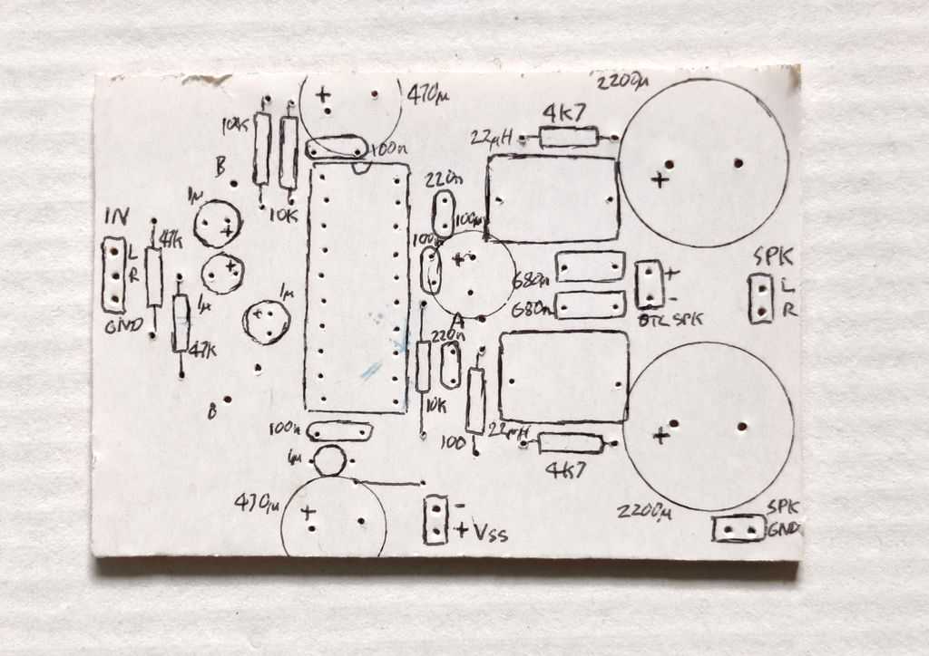
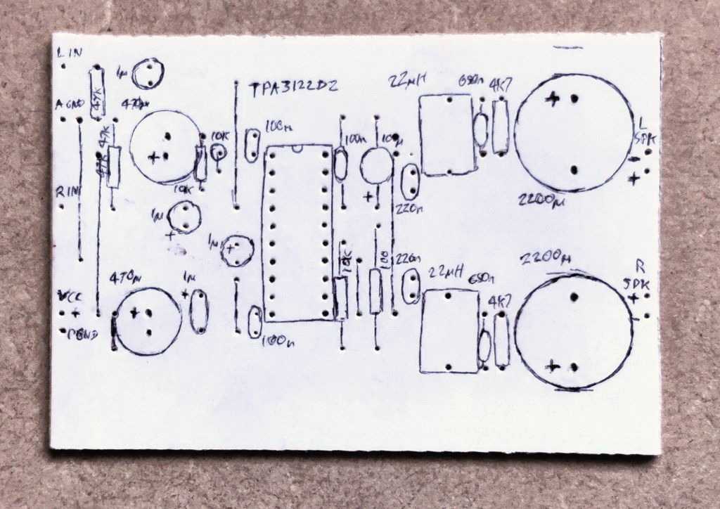
Above: Top layer layout of board, before adding components
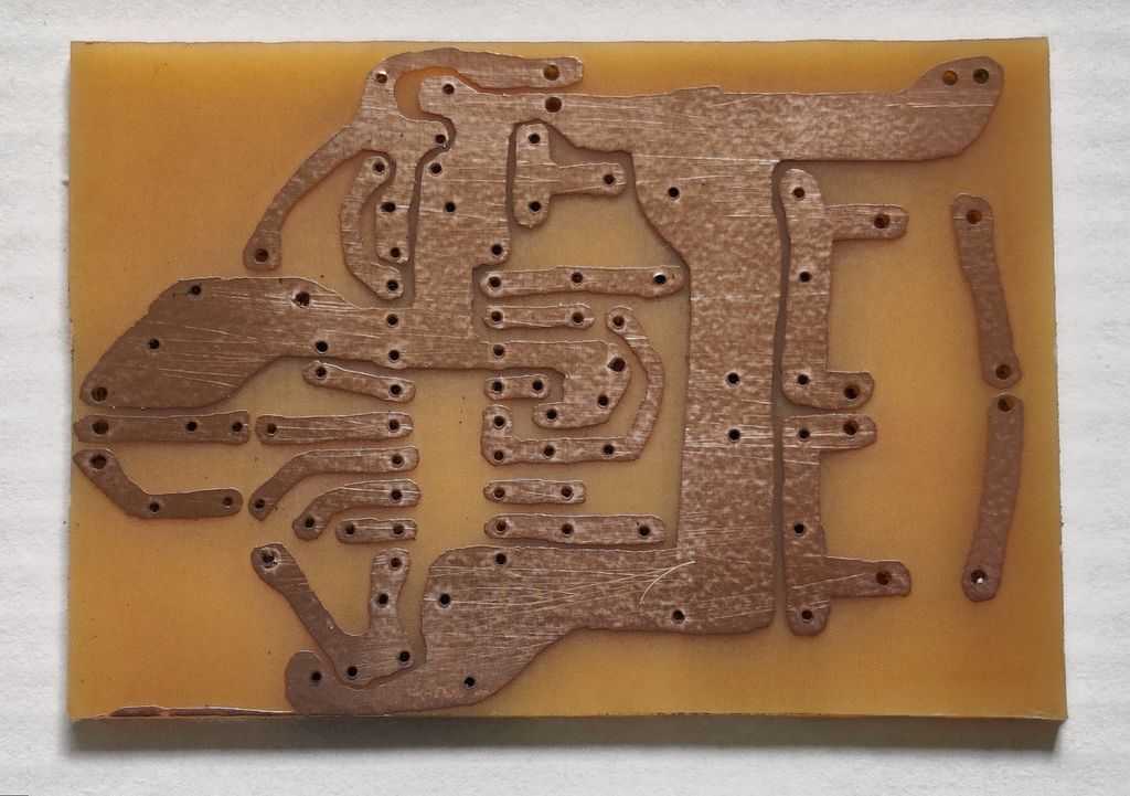
Above: Bottom view of board layout, before soldering
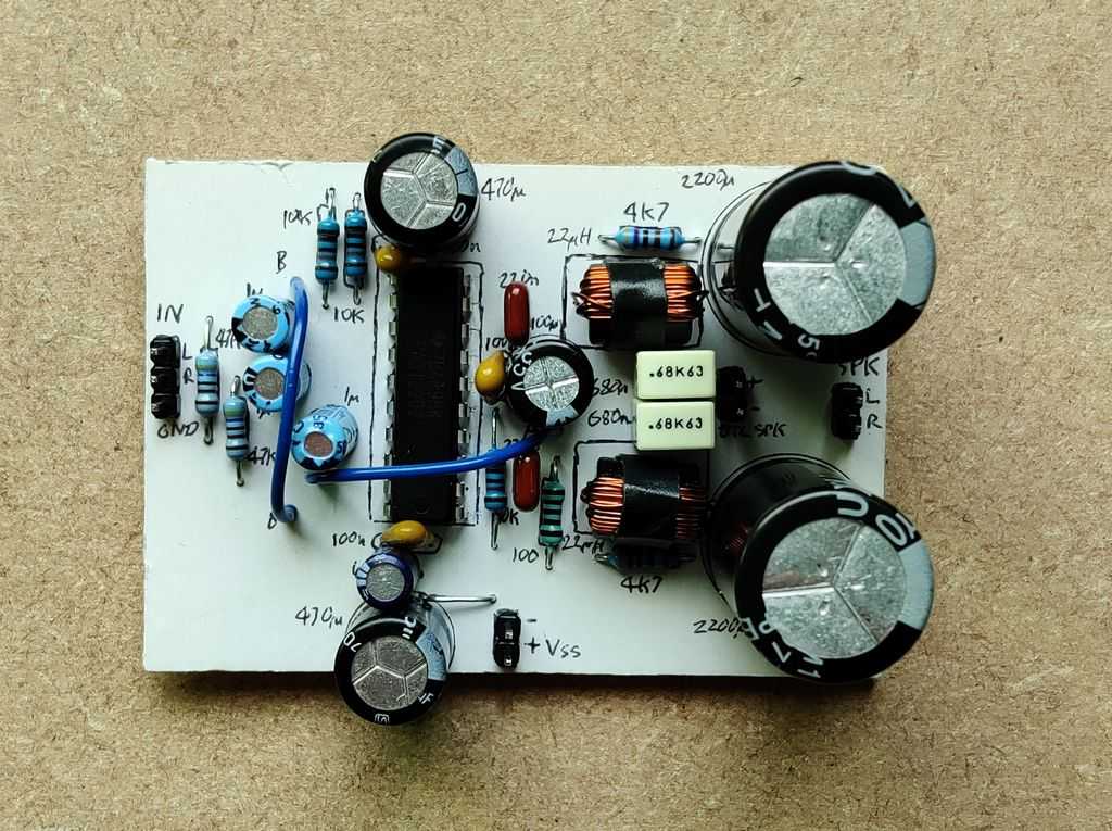
Above: Top view of board with components
Stripboard
As the TPA3122D2 / TPA3125D2 chips are DIP style chips, they will fit into standard stripboard / Veroboard, allowing this amplifier can be built without requiring a custom PCB. I advise against any breadboard or point to point build.
For DIP style chips on stripboard, you need to cut the traces so that none of the pins either side of the IC connect to each other. The layout I've shown below and performs ok in this configuration, but it does not perform as well as the custom PCB.

As the stripboard layout cannot make use of a ground plane for a low resistance path for ground currents, I suggest applying solder on all ground potential strips to lower the resistance of the board as much as possible. Do this after soldering components.
The areas in dark orange indicate where cuts in the strips are made. This easiest done with a dedicated stripboard cutter tool, but can also be done with a modelling knife, drill bit or whatever you find easiest. Please note that there are cuts to shorten tracts even when they are not electrically needed. These are to reduce interference.
The grey lines indicate where two adjacent strips/tracks are bridged together to create one wider track. These are the ground tracks mainly and also the AVCC track. Do this bridging after soldering components, but as you bridge the two, be careful not to overheat areas where components are already soldered - especially at the IC itself.
Below are pictures of my completed layout above and underneath. Revision 2 of the stripboard version works almost as well as the custom PCB, but it has turned out to be a bit larger than the PCB version where there's much more freedom in component placement.
Note that my test version I did build a bit smaller than my layout above. This is because of the capacitor and inductor sizes allowed me to reduce the length of the board. I've also left a little extra width though which leaves space for mounting the board via screws. We have to remember on stripboard that drilling mounting holes for screws will short the tracks once assembled in place, so holes must be over unused tracks.
Above: Top layer layout of board, before adding components (first revision)
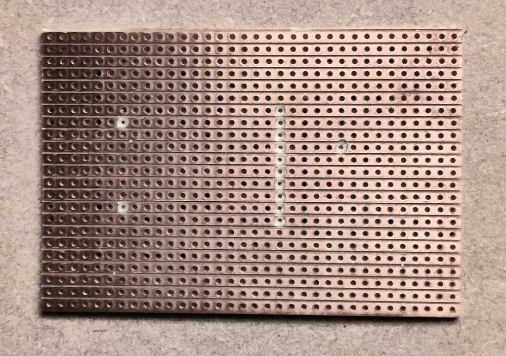
Above: Bottom view of stripboard, showing cut traces (first revision)

Above: Top view of board with components (second revision)

Above: Bottom view of board after soldering. Note the solder pours for the ground tracks (second revision).
Please note - the initial version I built was not stable and went into protection mode when operating above 25V, and when later measuring on an oscilloscope I found the switching frequency very bumping at the positive end of the output wave. The second revision is now stable.
Also note that the second revision still does not have the muting circuit improvement (R4, ZD1, R9, C17). You'll need to modify the layout if you wish to include these.
Gain control
The schematic, PCB and stripboard layouts above show the gain at 26dB - that's a voltage gain of 20 times, calculated as 10^(dB/20), so 10^(26/20) = 20). This gain is a fair compromise that will allow you to drive the TPA3122D2 or TPA3125D2 direct from most sources without a preamp.
The gain can be altered though and is controlled by the GAIN0 and GAIN1 pins (pin 15 and 14) which can be either high or low. They are TTL logic compatible, and anything above 2V is considered high, anything lower than 0.8V is considered low. This means you could control the gain from a microprocessor if you wanted to, but it wouldn't be enough steps to be a volume control though.
In my example, to obtain the 26dB gain, GAIN0 is pulled high by a 10k resistor to Vcc, and GAIN1 is pulled low by directing connecting it to 0V (GND). You can achieve other gains by configuring the high/low states per the table below:
| Gain dB | Gain voltage | GAIN0 | GAIN1 |
|---|---|---|---|
| 20dB | 10x | Low | Low |
| 26dB | 20x | High | Low |
| 32dB | 40x | Low | High |
| 36dB | 63x | High | High |
With a 28V input power, the TPA3122D2 can drive an 8 ohm speaker to about 12W RMS at 1% distortion. At a gain of 32dB, to calculate the voltage of this, it's V = √(12 * 8) = 9.8V RMS. Divide that by 20 and it's a 490mV RMS input signal required to drive the TPA3122D2 to maximum power, without distortion. For lower voltages (i.e. 12V), I found the output from a smartphone, or many other sources is just enough. For a 25V PSU though, I suggest to making the jump to the next gain setting of 32dB if you're intending to use a smartphone, mp3 player etc. sources.
Startup and shutdown
During my testing, I directly connected the shutdown pin to the VCC supply rail via a 10k resistor and connected mute to ground also via another 10k resistor.
This causes some startup and shutdown issues though:
- On a 12V switching PSU, there was a pop noise during power on
- On a 25V linear PSU, power on was initially unsuccessful, until I switch the PSU back off (music would then play as the power supply drained), and then back on before the PSU is fully drained
- For both power supplies, removing the power supply resulted in some rude noises once the voltage collapsed below 10V
To solve the power on / power off problem, I suggest implementing a time delay so that shutdown signal goes high (powering the amp on) after a short period. A time delay can be made with an extra capacitor between the shutdown pin and ground (shown as C17 in the schematic). With the resistor R4, this forms an RC time delay.
The shutdown pin is logic level - where 0.8V or less mean shutdown, and 2V or higher means not shutdown. The amplifier will power on somewhere between 0.8V and 2V. With an added 33µF capacitor that I tested, as the capacitor charges through both the Zener diode ZD1 and R4, this gives about 2 seconds delay. A 10µF capacitor C17 also works fine, giving less delay.
To solve the power off problem, the shutdown signal needs to go low before the power supply rails. By putting a Zener diode in series with R4, the shutdown signal will stop once the voltage collapses below the Zener diode voltage threshold. A resistor R9 in parallel with the capacitor C17 ensures the Zener diode conducts. Choose a Zener voltage a little less than your supply voltage, and no less than 10V. For a 12V PSU for example, 11V will do fine. This will even work with higher voltage power supplies, but to shutdown sooner, the Zener voltage should be closer to the supply voltage. I found success though with a 13V Zener on both an 18.5V laptop PSU and a 25V linear PSU.
Microprocessor control
Both the standby (shutdown) and mute pins are TTL compatible and are considered high with any voltage greater than 2V. That means this chip is easily interfaced with any microprocessor, including popular ones that run off 3.3V such as Arduino, PIC and Raspberry Pi. The mute and standby only draw 125uA so can be directly connected.
Using a microprocessor immediately solves any power on / power off noises because we can easily put the power on delays needed in firmware, and instantly power off.
I suggest a pull up resistor on the mute pin so when the microprocessor does not have an output voltage, the amplifier defaults to muted, and a pull down resistor on the shutdown connector so that the default state of the amplifier is shut down. For the latter, ensure that you don't connect the shutdown pin to an open drain port on your microprocessor though (i.e. for PIC, beware of port RA4).
Both the TPA3122D2 and TPA3125D2 have mute delays built in of 120ms, so when mute goes low, the speakers will run 120ms later. This should avoid any pops caused by the amplifier powering up, however you may still want to factor in a short delay of 100-200ms anyway in your microprocessor program.
Unlike other amps, the mute pin mutes the amp when the input is high, so you must drive this pin high initially, and then drive it low to unmute the amp. The shutdown (standby) pin operates like other amps though and the TPA3122D2 / TPA3125D2 will turn on when this pin is driven high.
Components
| # | Type | Quantity |
|---|---|---|
| U1 | TPA3122D2 or TPA3125D2 | 1 |
| ZD1 | Zener diode 11V ½W | 1 |
| R1,R2 | 4.7k ohm Resistor, ¼W Metal Film, 1% | 2 |
| R3,R5,R9 | 10k ohm Resistor, ¼W Metal Film, 1% | 3 |
| R4 | 470 ohm Resistor, ¼W Metal Film, 1% | 1 |
| R6,R7 | 47k ohm Resistor, ¼W Metal Film, 1% | 2 |
| R8 | 100 ohm Resistor, ¼W Metal Film, 1% | 1 |
| C1,C2,C3 | 100nF Capacitor, 50V+ Ceramic X7R or MLCC | 3 |
| C4 | 100µF Capacitor, 35V+ Electrolytic | 1 |
| C5,C6 | 1µF Capacitor, 35V+ Electrolytic | 2 |
| C7,C8 | 470µF Capacitor, 35V+ Electrolytic | 2 |
| C9,C10 | 1µF Capacitor, Polyester Film/Box (Best) or 35V+ Electrolytic | 2 |
| C11,C12 | 220nF Capacitor, Ceramic X7R or better | 2 |
| C13,C15 | 390nF Capacitor for 8 ohm speakers, 680nF for 4 ohm speakers, Polyester Film/Box or Mylar (Orange Drop, Green Cap) | 2 |
| C14,C16 | 2200µF Capacitor, 35V+ Electrolytic | 2 |
| C17 | 10µF Capacitor, 35V+ Electrolytic | 1 |
| L1,L2 | 47µH Inductor for 8 ohm speakers, 22µH for 4 ohm speakers (for Class D) | 2 |
| In,Vdd,SPK | 2.54mm header 8-pin (cut as needed) | 1 |
| Cable, connectors | ~ |
Per my suggested stereo schematic above, 27 components (including the IC) are required to build the amplifier. That's a lot more than most amplifiers I've featured and limits its portability, but it is a stereo Class D amplifier and it's still a reasonable component count that won't cost much or take long to build, and the PCB is still fairly compact.
The TPA3122D2 / TPA3125D2 needs plenty of bypass capacitors. C2/C7 and C1/C8 are the usual ceramic + electrolytic power supply decoupling. Per datasheet recommendation, I've repeated these bypass capacitors for each half of the amplifier. The 100nF ceramics (C1 and C2) should be multi-layer ceramic (MLCC) capacitors. The electrolytic capacitors (C7 and C8) should be 470µF or 1000µF each and must be orientated correctly with + in the positive power supply.
The AVCC pins (16 and 17) also need bypass decoupling. C3 provides this and should again be a multi-layer ceramic (MLCC). C1, C2 and C3 need to be as close to the amplifier pins as possible.
A capacitor is also needed at the BYPASS pin 6 (C5) and another one on the VCLAMP pin 9 (C6). These should both be 1µF electrolytic or better. My initial experiment with a 1µF MLCC for the VCLAMP capacitor on the stripboard layout caused instability (clicking) and I found a 4.7µF electrolytic resolved this.
The BSL output capacitors (C11 and C12) should once again be ceramics again, ideally MLCC, and they should be close to the amplifier pins again. The inductors (L1 and L2) should also be close to the amplifier IC.
EMI filter capacitors (C13 and C15) should be Polyester Film / Box or Mylar. Use 390nF for 8 ohm speakers, or 680nF for 4 ohm speakers (including BTL into a single 8 ohm speaker). I did originally try ceramic MLCC but the filtering performance of these was much worse.
All electrolytic capacitors must have a voltage rating of a few volts or more greater than the power supply you want to use. Therefore, 16V capacitors are fine for a 12V PSU, but if you want to go higher with the voltage, get 25V or 35V rated capacitors.
As the TPA3122D2 / TPA3125D2 are single supply amplifiers, they generate a virtual ground internally that is half the supply voltage. This allows the audio input signal to swing above and below this virtual ground.
The input capacitors C9 and C10 protect that DC voltage offset from reaching your input source. These are 1µF input capacitors in the datasheet, and that's enough to get good bass response. I used 2.2µF in my test though, because of what I have. Polyester is preferred for best audio quality, but an electrolytic works fine too and unless you're using this amp for the absolute best speakers in a quiet environment, you'll unlikely to notice the difference. The + pin of the electrolytic must be facing the amplifier pins.
As the voltage the capacitor is blocking is half the supply voltage, a 25V rated capacitor is fine for C9 and C10, but 1µF electrolytic capacitors are usually 50V or 63V rated or higher anyway.
The 10k resistors (R4, R5 and R3) are all the logic pull up/pull down and can be any cheap ¼W 5% resistor. The input and output resistors to ground should be 1% metal film ¼W or better, as should R8.
The tricky components are the inductors L1 and L2. Chances are you won't have them and will need to buy them for this amplifier. You need 47µH for 8 ohm speakers, or 22µH for 4 ohm speakers (or 8 ohm in bridge tied load configuration).
The inductors should ideally be rated for Class D amplifier use, such as those from Coilcraft or other manufacturers. This may end up costing more than the amplifier itself, but sorry, that's the bad news! I did end up getting some cheap 20µH ZXFN1000 inductors myself though, and they sound nice. You can of course use normal power inductors, however they might impact sound quality, such as adding distortion particular frequencies. Air coil toroidal inductors are apparently good though, but large!
The other bad news for single ended speaker drive is you need capacitors to block the DC (C14 and C16). These need to be rated for the supply voltage you are giving the TPA3122D2, so they are not stressed when driving the amplifier to its maximum, so if you're intending to run this amplifier at 30V, look for a 35V rated capacitors for C14 and C16. You need a minimum of 1000µF for 8 ohms, or 2200µF for 4 ohms for good bass response. They'll unfortunately cost you both real estate on the board (adjust my layout if needed), and also your wallet a little.
If you're using my mute circuit, the choice for the components ZD1, R4, R9 and C17 are not too critical. The Zener voltage needs to be higher than 10V, and the supply voltage needs to be a few volts higher than the Zener diode. C17 needs to have a voltage rating equal or better than the power supply your using. The power drawn by the circuit is small, so the power ratings of R4 and ZD1 can be the normal ¼W for the resistor ½W for the Zener.
Bridging (BTL)
When you look at the power outputs in the data sheet, bridging the TPA3122D2 definitely seems attractive! The output power vs supply voltage graph on page 9 (figure 21) seems to imply that we can go all the way to 45W per channel (at 1% distortion) into an 8 ohm speaker when supplied with 30V!
This is suspicious though. In BTL, an 8 ohm speaker will look like 4 ohms to each amp half... so why is the datasheet OK going to 30V in this case, but when driving a 4 ohm speaker single ended it does not give any output for supply voltages above 18.5V? See figure 11 graph on page 7. Other graphs indicate that TI have done some tests into 4 ohms at 24V though (example figure 5, which shows about 17W at 1% distortion).
Given that, I also wouldn't suggest you go above 18V into an 8 ohm speaker in BTL. This is a more realistic 19W per channel power output at 1% distortion. That's some fair power, but there are other advantages:
- In BTL mode, the power output on lower voltages is more reasonable. For example, on 12V, we can reach 8W per channel at 1% THD, matching the output of the STA540. That's also much better than the single ended power of just 2W
- Our PCB can be made a little smaller because the large DC blocking capacitors (C14, C16) on the speaker outputs are no longer required
Do not use BTL into a 4 ohm speaker. Sure Table 3 in the datasheet seems to list it as a possibility - but nowhere else is BTL in to 4 ohms specified, and nor is single ended into 2 ohms. Update: Table 4 in the TPA3125D2 datasheet correctly only lists 8 ohms for BTL, so assume that is sensible! It does however (in Absolute Maximum Ratings table) list 6 ohm as a possible minimum load impedance.
The disadvantages?
- For a stereo system in BTL - we need two PCBs. That's twice the chips, twice the inductors and all other components (except the output DC blocking capacitors)
- We need a source that can create the inverted input
- THD across the output will be slightly worse in BTL, but unlikely to be noticeable
Sadly, unlike other amps, the TPA3122D2/TPA3125D2 does not have anywhere we can tap into for an inverted signal to send to the second amplifier (such as the feedback resistor), so we'd need to create it ourselves.
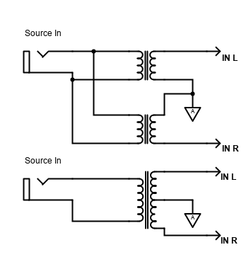
Some sources might already have a balanced output, but the majority are unbalanced meaning we have a signal and a return (on ground). To create the inverted signal, you can either use 1:1 ratio transformers (i.e. 600:600 transformers). A centre tapped one will give both the original, inverted and return ground. Alternatively, two transformers can be used where the inputs of each would be in parallel with the source, the output would be connected to each TPA3122D2 input mirrored from each other. This is illustrated below (the top connection of L1 gives the non-inverted signal to the left amp, the bottom connection of L2 gives the inverted signal).
Transformers do affect audio quality though and will drop some low frequencies (bass). You'd also need two centre capped, or four without the centre tap, for a stereo BTL configuration, and this will cost some pennies and take up a fair bit of space! Examples of both is shown below:
An alternative is to use an op-amp to invert the signal to the second input. ESP Project 14 - Bridging Adapter is the solution here. As the TPA3122D2 / TPA3125D2 are single supply chips, we'd want to use the single supply version of this bridging adaptor too. That's the last schematic (figure 4) on that link. If you're using a high voltage of 24V for the TPA3122D2 (as mentioned going higher is a risk!), you might want to consider using a 7815 to regulate that voltage for the op-amp. My built adaptor worked fine with a 15V Zener diode off a 19V PSU though.
Both my PCB and stripboard layouts are easy enough to adjust so that the DC output capacitors are not installed and the + and ‐ speaker output taken from where the + side of the capacitor was. The PCB has two separate pins for this.
Bear in mind that a BTL amplifier will output almost 4x the power into the same 8 ohm speaker that it was when single ended. This is an extra 6dB of gain, so you may need to consider configuring the GAIN0 and GAIN1 pins appropriately - 20dB is possibly all you'll need.
I've tested both my PCB and stripboard TPA3122D2 amplifiers via a bridging adaptor. I cooked my stripboard one a bit by trying to bridge into a 4 ohm speaker with a 19V PSU, which resulted in a burning smell (update 2024 revisit - not cooked, seems fine after layout and capacitor adjustments!). There's confirmation that it really cannot drive 4 ohms bridged (or 2 ohms single ended)! It also smelt a bit bridged into 8 ohms, but still worked.
My custom PCB TPA3122D2 also worked fine off 12V into an 8 ohm speaker and could go louder than before.
A class AB alternative such as the STA540 in comparison will still give the same power output as the TPA3122, but once again the circuit for the STA540 is much simpler and smaller, especially as no bridging adaptor is needed, has two channels instead of one. The STA540 will need a fair sized heatsink attached and a bigger power supply (amps) though.
Making a 'system'
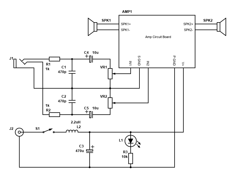
If you want to build your own stereo amplifier system, you'll need a little more than the circuit and components above.
- A power supply - see below, but suggest an external power supply
- A DC jack such as a standard 2.1mm jack. It should match the plug on the power supply
- A power switch, such as a slide switch, toggle switch or latching push button
- A power LED and current limiting resistor (you may have an LED in your power button you can use)
- 3.5mm jack input or phono sockets for connecting your source
- A dual gang potentiometer, 10k log is recommended
- Optional, but recommended, capacitors to block radio interference
- Optional, but recommended, a capacitor and inductor to improve PSU noise
If you set the gain to 26dB, 32dB or 36dB, it's unlikely you'll need a preamplifier and you'll be able to use most sources directly. This could be your TV, smartphone, a Bluetooth audio module, Chromecast audio (if you can find it to buy) or many other devices.
When connecting all connections, tightly twist the related wires together. This applies to all related connections where there is a signal and a return, so twist the L/R input with the signal ground together, twist each speaker +/- wires together, and twist the voltage + supply and power ground together.
Twisting related flow/return wires together likes this both prevents them radiating interference, and also protects them from interference. Each twisted set in a system should be kept away from each other and if they must be close, let them cross at right angles and don't run them parallel to each other. This is to reduce hum.
The PCB layouts above have the signal (analogue) and power grounds joined together at the board, therefore do not have these connecting anywhere else to avoid hum caused by ground loops. If you do have a wider system, ensure these power and signal grounds are not joined at another point.
The potentiometer should be a dual gang one, so both channels are adjusted together. If you are building a bridge mono amplifier though, this can be a single gang one that is placed before the bridging adaptor. 10k Log potentiometers are ideal. It will have three pins per channel. The first pin will be the one connected to signal ground, the middle pin to the audio input and the final pin as the audio output. This will ensure that turning the volume control clockwise raises the volume, anti-clockwise lowers it.
Before the volume control is an RC low pass filter. The component values are not too critical here, it's just to ensure signals of MHz's are removed so with the combination of 1k ohms and 470pF (picofarads), frequencies above 340kHz are removed. This will remove any GSM pulsed buzz / interference from mobile phones, as well as any AM radio stations creeping in.
At the power supply, the switch is first, on the positive line. I suggest getting a latching push button switch with an LED built in for convenience but check whether the LED needs a resistor or not (some are 12V ready). Otherwise having a separate LED to indicate whether the power is on is useful. The value R3 should be adjusted to suit your power supply and LED type (search for LED resistor calculator).
Then there is a filter formed by a 220µH power inductor (capable of handling 4A current) and a 470µF capacitor (this must be a low ESR type). These are there to reduce the ringing/whining noise from noisy SMPS power supplies. Anything above 500Hz on the PSU is cut. You may not need the inductor if your power supply is quiet, but I still suggest the capacitor for smoothing the voltage.
Power Supply
I recommend, especially for beginners, that an external power supply is used. This should be a linear power supply or switching power supply that is suitable for audio/video use (i.e. a 19V laptop power supply). These types of power supplies are easy to obtain.
Be wary of cheap power supplies ordered from the far east and elsewhere because although they may work fine, they won't be safe in overload or other situations (lightning strikes etc.). The CE symbol on these devices is either fake or means 'China Export' and isn't the European certification that guarantees the product conforms with health, safety, and environmental protection standards.
With a 19V supply, this amplifier can give nearly 6W into 8 ohms at a reasonable 1% distortion, single ended. For many applications this will be enough. Because it's Class D, this means the power supply only needs to be 15W (that's 0.8A output for 19V).
To get more power, get a PSU above 19V. These suddenly become rarer. Be warned about using power supplies intended to power LEDs or charge appliances because they'll be too noisy to use on an audio amplifier.
In BTL mode, the TPA3122D2 will give a much better 20W off a 19V PSU. You could have 2x TPA3122D2 bridged amps and a bridging adaptor running off a 65W laptop PSU happily.
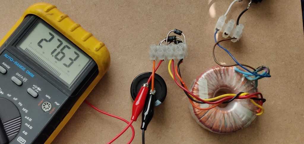
Above: A knocked together linear PSU with an 18V AC toroidal transformer, 4x 1N5404 diodes, a 10,000µF 50V capacitor and some wires/sockets.
If you decide to build your own power supply, you can use a 18V AC transformer to get about 25V DC when rectified. That's good for 9W per channel (at 1% THD) and a small 30VA transformer would be enough. See the TDA2003 article for a suitable schematic but bear in mind you will be working with mains electricity. MAINS ELECTRICITY IS DANGEROUS - make sure you are qualified, understand your liability and ensure that your build is properly earthed (not like my quick test).
Performance
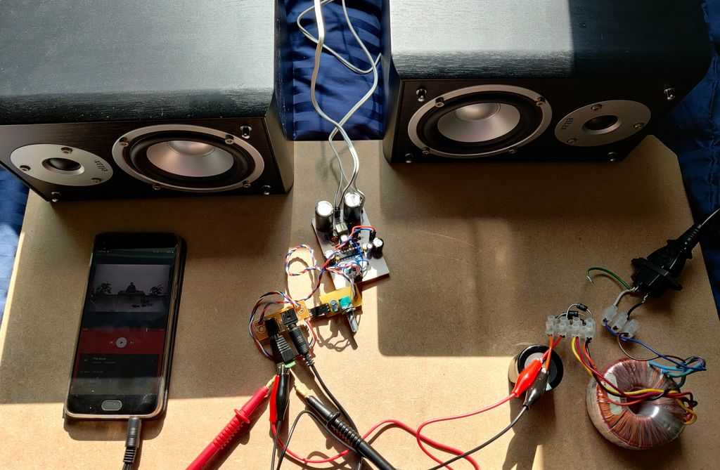
Above: Testing the TPA3122D2
When wired correctly, and good quality components picked, the TPA3122D2 is a pretty good amplifier. It sounds absolutely fine and is perfect for driving speakers of various sizes. Because of the limited power output, speakers with high sensitivity are best if you need high volume, but on most speakers it's absolutely capable for indoor use, and this amplifier could even be considered for high quality Hi-Fi use, and definitely good for TV use.
Please see below for some captures of the output. You'll see that there is 250kHz wave from the class D switching. The amplitude of this wave increases as the power supply voltage increases, for example 194mV on 18V supply, 270mV RMS on 25V supply. This was measured into an 8 ohm load but using 20mH inductor and 640nF for filtering, so not optimal, but the same increase was observed with a 4 ohm load too.
250kHz is ultrasound beyond human hearing, and animals and it's also likely to not be reproduced through most ordinary speakers and especially subwoofers, which is where class D amplifiers are really best. If you are after the best quality and pure audio though, class AB and A amplifiers powered from a linear power supply will be best for you.

Above: 1kHz wave using 18V supply into 4 ohm load, custom PCB layout. This is the best performance of my tests, though lower supply voltages will
result in better still at the cost of max power output. The thick trace is because the large 1kHz sine wave is recreated using a 250kHz switching
frequency.

Above: Audio silence using 18V supply into 4 ohm load, custom PCB layout. This shows the 250kHz switching frequency when there is no audio playing.

Above: 1kHz wave using 18V supply into 8 ohm load, custom PCB layout (non-optimal filtering inductor and capacitor). I streched this out a bit more
so you can see a little of the switching.

Above: Audio silence using 18V supply into 8 ohm load, custom PCB layout (non-optimal filtering inductor and capacitor). Here the switching frequency
climbed from 176mV to 194mV into 8 ohms because I'm still using the 20µH inductor and 680nF capacitors for filtering.

Above: 1kHz wave using 25V supply into 8 ohm load, custom PCB layout (non-optimal filtering inductor and capacitor). The line is thicker due to the
magnitude of the switching frequency increasing with the power supply voltage.

Above: Audio silence using 25V supply into 8 ohm load, custom PCB layout (non-optimal filtering inductor and capacitor). This shows an increase of
magnitude to 270mV RMS from 194mV RMS just by increasing the supply voltage from 18V to 25V.

Above: 1kHz wave using 18V supply into 4 ohm load, Stripboard layout (rev. 2). Performance is very similar to the PCB (first oscilloscope image
above), but there is a bit more gain - possibly because the chip itself is different.

Above: Audio silence using 18V supply into 4 ohm load, Stripboard layout (rev. 2). This shows the 250kHz switching frequency after filtering. The
181mV result is almost as good as the 176mV for the PCB board.
Under testing, the efficiency of class D was very evident. The TPA3122D2 chip itself was barely warm - cooler than my 50W 8 ohm resistor load.
So, the TPA3122D2 really suits systems where heat removal is a problem. If it's not, you'll find a Class AB amp such as the STA540 or TDA7375 both easier to construct and just as good if not greater sounding. The boards for these amplifiers (whether stripboard or a custom designed PCB) will be smaller than the equivalent TPA3122D2 board, you just need a heatsink which could be mounted on the rear or side of the case with alternative Class AB chips.
As already mentioned, this amplifier ideal for your low power battery operated devices. You can't go lower than 10V with the TPA3122D2, and without bridging, the power produced output is quite low. Because of the number of components, the PCB ends up being quite large too, limiting portability. Due to its efficiency though, if you can get battery power giving 18V or more, it'll run longer on batteries than any Class AB amplifier. A bridged mono portable speaker would give the best power output; however, you'll need to have room for the bridging adaptor too.
All things considered though, it's a good amp! It sounds really good and as my first experience of a DIY Class D amplifier it was easy enough to work with and it's impressive that it can be driven loud, whilst generating hardly any heat at all!
References:
TPA3122D2 datasheet
TPA3125D2 datasheet
TPA3122D2 EVM Evaluation module
HiFiDuino Dual-Mono TPA3122D2 AMP
Texas Instruments AN-1849 An Audio Power Supply Design
ESP - Bridging Adapter For Power Amplifiers