
TDA7439/TDA7440 - Stereo Quad Input Digital Audio Processor
Warning: The TDA7439 in PDIP format is discontinued, however the SO28 (surface mount) TDA7439DS is still available as March 2021 and much of the information here is applicable. The TDA7439 can still be found and it's probably not a chip popular to make fake substandard copies of, but there's always that risk.
Recommended Experience : intermediate to advanced, custom PCB needed, microcontroller needed
TDA7439 application
Quick facts TDA7439
- Four stereo inputs with gain control
- Volume / attenuation control in 1dB steps
- Balance / channel attenuation control in 1dB steps
- Three band tone control in 2dB steps
- Gain: 0 to 30dB adjustable
- Power supply: 8V to 10V single supply only
- Datasheet available here
Guide
The TDA7439 is a single chip audio processor that will allow you to replace a pre-amplifier, volume, balance and three band tone controls with just a single chip, a few external components and a microcontroller.
It's stereo, making it applicable for small sized 'Hi-Fi' systems, car-radio (two channels), or small active stereo speakers.
Whilst you could use multiple TDA7439 to build a multi-channel system, your microcontroller will need to support separate I2C/TWI channels (could be possible with software driven I2C) since the address per TDA7439 chip isn't configurable.
The performance of the TDA7439 is great, and whilst I wouldn't say it's aimed for 'true' hi-fi systems, it's certainly good quality and capable of replacing fully analogue op-amp based circuits in many designs and a good alternative to LM1036 or TDA1524 circuits.
It does need to be controlled by a microcontroller via the I2C bus (also known as TWI or Two-Wire Interface). This might put-off novice builders, but the advantage this brings is possibilities of infrared and/or bluetooth based remote control, or any other applications you can think of!
The control method on the I2C bus is quite simple. Only two wires (a clock signal, and data signal) are needed and bytes are sent out serially one bit at-a-time (more details below).
Many microcontrollers are capable of driving the I2C bus either with built in hardware or by software bit-banging and chances are the manufacturer, software compiler or someone else has written a library for I2C/TWI communication - it's very popular!
I typically use PIC microcontrollers. Some have I2C hardware support, others don't. Arduino is a popular alternative though and very well supported by the community. You could also use a Raspberry Pi or other small computer. That's a bit heavy handed for a preamp, but if your project already uses one for other features then the Pi's native I2C bus support makes communicating with the TDA7439 quite easy.
Circuit
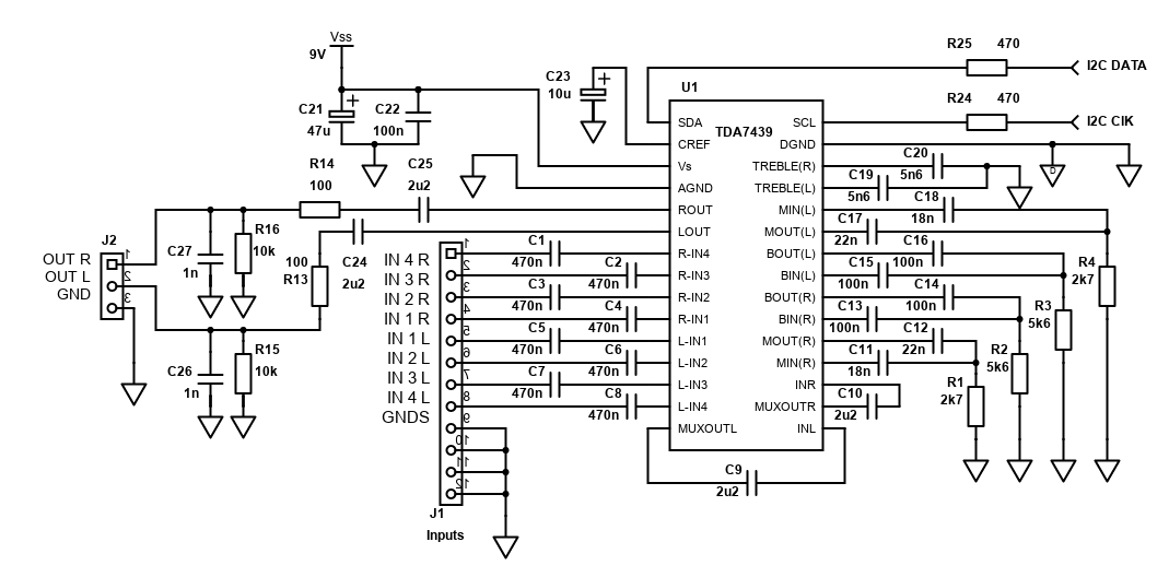
The schematic above is based on the test circuit ST Microelectronics datasheet. I've added a few components to the stereo output to block the DC offset, provide an output impedance that will work with many amplifiers (including all the ones on my site) and a low pass filter for RF/GSM noise suppression.
Note: The pull-up resistors for I2C data and clock are NOT shown in the schematic, but are required. Typically they are installed at the microcontroller as you only need one pull-up resistor on the clock and data for all devices connected on the bus. These pull-up resistors should be 10k - one from the I2C DATA input to the microcontroller power supply (i.e. +5V or +3.3V), and one from the I2C CLOCK input to the microcontroller power supply again.
Another note: The schematic is for the TDA7439. The alternative TDA7439DS is basically the same, but the pinout is different. Refer to the datasheet.
The TDA7439 is a PDIP chip. That means it does not have the standard 2.54mm (0.1 inch) pin spacing of traditional DIP chips. That means it isn't going to fit into stripboard, and it also won't fit any commonly available sockets. The distance between each pin is about 1.8mm so a custom PCB is a must.
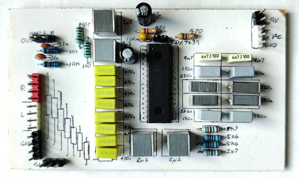
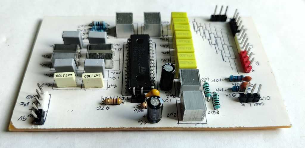
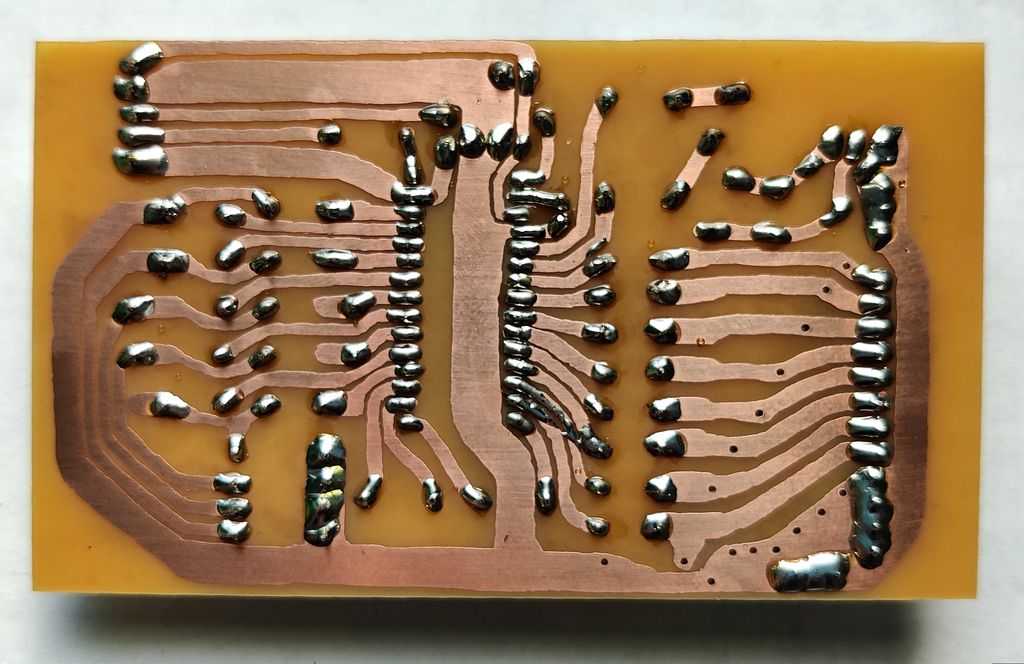
I've designed and built a PCB that was used successfully in my STA540/TDA7439 amplifier and the layout I came up with is shown below, in my usual hand-drawn style!
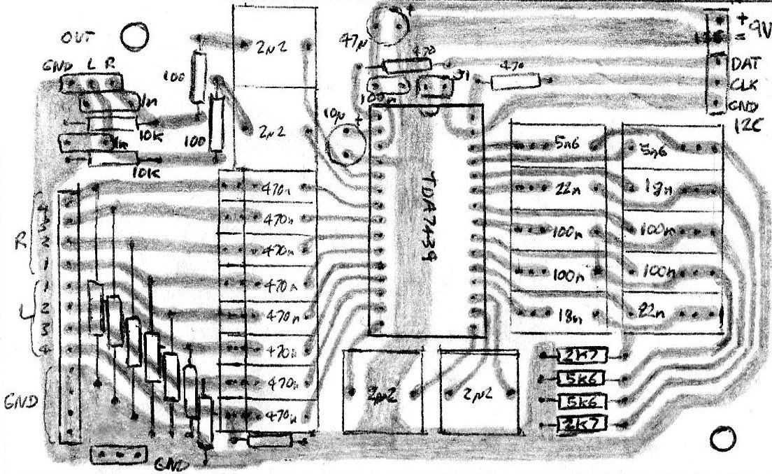
I've tried to make the layout somewhat forgiving to the types of capacitors you can get, whilst keeping it to a small 93 x 57mm layout. There are many different capacitor variants though so you may need to adjust the board for what you have or can obtain.
There is a header for a two pin jumper above the TDA7439 chip used to connect the digital and analogue grounds together. In order for the TDA7439 to work, they have to be connected somewhere. If you've two separate PSUs (one for the TDA7439, one for the microcontroller). at the board is best. If the PSUs are already connected together though, leave the jumper off so a ground loop isn't created.
The 8 unmarked components bottom right are optional axial lead capacitors if noise is a problem. 220pF to 1nF will work fine to suppress frequencies above 20 to 200kHz that we can't hear anyway. I left them out in my testing and final build though anyway.
Components
Most of the components are capacitors. C1 to C20, C24 and C25 are all in the audio path and therefore should all ideally by polyester capacitors. C24 and C25 can be electrolytic if you prefer to save money however if these are used, the positive terminal must face the TDA7439.
C21 and C23 are standard electrolytic capacitors. Just ensure they are rated 16V or better and oriented per the schematic or they'll fizzle or bang! Both should be close to the TDA7439 in your PCB layout, especially C23.
C22, C26 and C27 are standard ceramic capacitors or MLCC. C22 must go as close to the TDA7439 as you can get it in your layout.
Most of the resistors are recommended to be 1% metal film, 1/4W or better. Only the resistors on the I2C bus (R24 and R25 plus two pull-up resistors not shown) can be 5% carbon as they're not in the audio signal.
The components shown are as per the standard datasheet recommendation, however you can alter the band pass bass, mid and high pass treble filter by adjusting the capacitors and resistors appropriately.
For my build, I was not that interested in controlling the mid but interested in controlling bass at different frequencies. Therefore, I've configured the bass tone control as a 'low-bass' or 'sub-bass' control, with the T-filter set to a centre frequency of 46Hz, gain of 9.8 and Q of 2.8.
The components I used to get this setup are 220nF capacitors for both C13 to C16 instead of 100nF, and 5.6k is kept for R2/R3.
The mid will control a higher frequency of bass of around 117Hz, gain of 9.57 and Q of 2.75. C11, C12, C17 and C18 become 150nF instead of 18nF/22nF, and R2/R4 become 3.3k instead of 2.7k.
The frequency, gain and Q formulas are given in the datasheet, though I have put together a spreadsheet for calculating the values.
For treble, I used 4.7nF C19/C20 capacitors instead of 5.6nF. That will lower the high pass cutoff, but it works well enough. I don't intend to alter treble much anyway.
Control
As mentioned the TDA7439 cannot function alone and you'll need a small microprocessor / microcontroller in order to control the TDA7439.
Giving the full solution is beyond the scope of this article since the display used, buttons or control used will all be to your preference! A bare-bones system will need a microcontroller, a screen (LCD or LED) for visual output, and control can be either via buttons or infrared remote control (or both). More specialised control such as Bluetooth via a smartphone app, or serial/USB via a PC would also be possible if you can write the software.
The communication between the microcontroller and the TDA7439 is done via an I2C bus. This requires two wires (a data signal and clock signal) and is quite simple to understand and code. I suggest to pick a microcontroller with I2C leader (master) support built in as it makes writing the code a little easier, however writing a fully software based solution is also possible.
My STA540/TDA7439 amplifier build uses a PIC16F873. This is a large and somewhat legacy chip, but it does have the I2C support built in. Head to my build page to find out some software examples. Although they are specific to that build, you'll hopefully find them as good building blocks to build your own TDA7439 project.
For those who prefer other microcontrollers (such as the popular Arduino), you'll need to consider the following in your code:
- An initialisation routine to tell your microcontroller what pins the bus is connected to, baud rate as well as initialisation for other peripherals.
- Functions to send the relevant bytes to the TDA7439
- Controls to interact with a human, such as buttons, rotary encoders, IR remote control, LCD/LED displays etc - all per your preference!
The datasheet gives you good examples of what data to send to the TDA7439 in order to control it. I do have a summary with logic analyser captures on my STA540/TDA7439 amplifier article though.
Power Supply
The TDA7439 needs a single supply power supply giving 8 to 10V DC. It must be regulated. The simplest version is to use a 9V regulated external PSU (wall-wart) dedicated to the TDA7439.
The supply current is 10mA max. It should be easy to find or build a power supply exceeding that many times. Even running the chip off a 9V PP3 battery seems possible (though 6 1.5V AA/LR6 would be better)!
Having a power supply dedicated to the TDA7439 is recommended and reduces your chances of hitting ground loop issues.
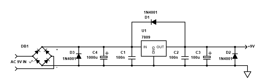
If you want to build your own PSU, since the current draw is low, a linear regulator is fine for a mains powered device. It's unlikely a heatsink will even be required for them. I suggest the fixed 7809 or 78L09 linear regulator options, or adjustable one such as the LM317 or LM317L with resistors configured to output around 9V (I used the LM317 in my build).
These regulators should be fed with a DC voltage at least 2.5V higher than the output (9V, so min input of 11.5V). You can easily get this kind of DC voltage by using a bridge rectifier following a 9V AC transformer (preferably external). Below is an example schematic.
Although the current draw is very low at 10mA maximum, There is no standby possibility though so I suggest switching the chip on/off via a small relay or physical switch at the unit, especially if battery operated.
For many integrated designs (TDA7439 preamp, power amplifier, microcontroller) - 8 to 10V is probably too low compared to the power supply of the amplifier (but may be fine if you're building a 2 to 4W amp). It's highly likely to be too high to share the same power supply as the microcontroller too (typically 5V or 3.3V). Therefore I suggest the separate power supply.
If you are building a fully integrated unit with a mains input, you could build a simple small power supply using a PCB mount 9V 1.5VA AC transformer (with fuse before it) followed by a bridge rectifier (voltage will be about 12V DC after this), capacitor and 9V regulator and associated components as shown above.
If you do wire a power supply using mains voltage, you must be suitably qualified, Death or serious injury may result from mistakes.
If you intend to regulate the power to 9V from another DC power source in the system (such as the amplifier PSU), you might hit ground loop issues, particularly if switching power supplies are involved. In my build I used a linear regulator to drop the amplifier's PSU to 12V, followed by an isolated DC-DC convertor (12V to 12V), followed by a 9V linear regulator with coils and capacitors to suppress noise. See my STA540/TDA7439 amplifier build article for the details about this PSU.
Performance
My PCB is quite small for both the TDA7439 and its associated microcontroller. For that, I've a fully featured pre-amplifier, volume, balance and tone control.
It works great. Certainly I'm happy with the performance when combined with my STA540 amplifier. For me the advantage is the size is much smaller than fully analogue solutions, control is simplified to just an infrared remote control for my needs compared to having and mounting many potentiometers and switches.
Whilst the requirement to program a microcontroller or something else to send those I2C bus signals to the TDA7439 does add time and complexity to the solution, the result is worth it (especially if you're interested in the coding side too)!
Whilst the sound quality is great, there are limitations to the volume adjustment range, and tone control range. I feel that +/-2dB is way too much jump on a tone control to do 'proper' Hi-Fi adjustments. You'd prefer to make smaller controlled adjustments to the tone in real Hi-Fi whereas on the TDA7439 raising the treble for example by 2dB makes a huge difference to the sound.
On the volume, again the adjustment is just 1dB at a time. That's mostly OK, but it only reduces down to -47dB so in order to reach quiet volumes the input gain would need to be set to zero and you may have to apply L/R speaker attenuation in order to get quiet enough, but be careful that it can still go loud enough too!
Real Hi-Fi applications should consider using the PGA2310 as a digital volume control (I use this in my main 5 channel Hi-Fi amplifier), but you do lose the tone control abilities.
For a smaller system though, it's great and the PCB size needed is much smaller than would be needed for fully analogue controls, even when you factor in the microcontroller.
TDA7440 application
Quick facts TDA7440
- Four stereo inputs with gain control
- Volume / attenuation control in 1dB steps
- Balance / channel attenuation control in 1dB steps
- Two band tone control in 2dB steps
- Gain: 0 to 30dB adjustable
- Power supply: 6V to 10V single supply only
- Datasheet available here
The TDA7440 is the same circuit as above but the pinout is different again and it has no mid-range tone control so C11, C12, C17, C18, R1 and R4 can all be ignored.
The same basic notes apply so read all the above but during operation, as there is no mid control, sub address 4 (0100) is ignored.
The TDA7440 can operate off a slightly lower voltage down to 6V, giving more flexibility for the design. This puts it in applications such as portable battery operated amplifiers (such as a TDA2822M or TDA7266). In this application, 6V would typically still be too much for many microprocessors, however an LDO (low dropout regulator) could be used to regulate it down to 5V.