
TDA7264 DIY Guide - 25W Stereo Single Chip Power Amplifier
Recommended Experience : intermediate, knowledge of amplifiers, split rail power supplies, heatsink attaching, and mains qualification
Introduction
The TDA7264 is an 8 pin Multiwatt device that provides an easy to build, high quality stereo amplifier with a fixed gain.
Quick facts
- Power output: 25W + 25W into 8 ohms at 10% 1kHz distortion with power supply +/-20V
- Power output: 20W + 20W into 8 ohms at 1% 1kHz distortion with power supply +/-20V
- Power output: 25W + 25W into 4 ohms at 10% 1kHz distortion with power supply +/-16V
- Power output: 20W + 20W into 4 ohms at 1% 1kHz distortion with power supply +/-16V
- Dual amplifiers in one chip
- Short circuit protection
- Mute/standby pin
- Gain: 30dB (fixed)
- Power supply: +/-5V to +/-22.5V split rail supply
- Class AB
- Peak current limit 4.5A
- Datasheet available here
This chip is basically a smaller and easier to use version of the TDA7265 that has less pins, but a fixed gain of 30dB. It's intended for Hi-Fi / TV / Music centre application, and ideal for driving 8 ohm speakers, rather than driving 4 ohm speakers.
Guide
This simple single chip power amplifier has existed since 2004 and is still produced as of December 2022, indicating that it is popular.
- Just one chip makes a capable amp for a stereo system (i.e., a homemade or upgraded midi system).
- One chip + speakers can improve the sound from a TV set.
- Woofer, Mid and Tweeter amplifiers in active Hi-Fi bi-amp or tri-amp systems, thanks to its low distortion.
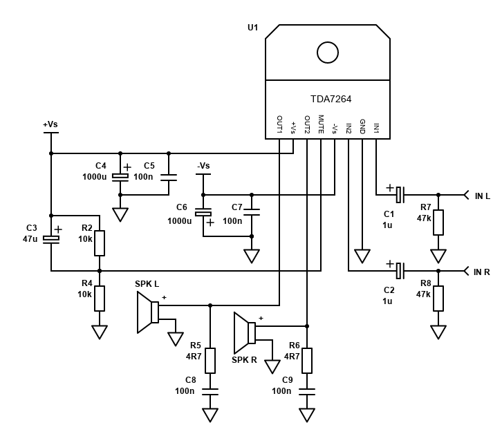
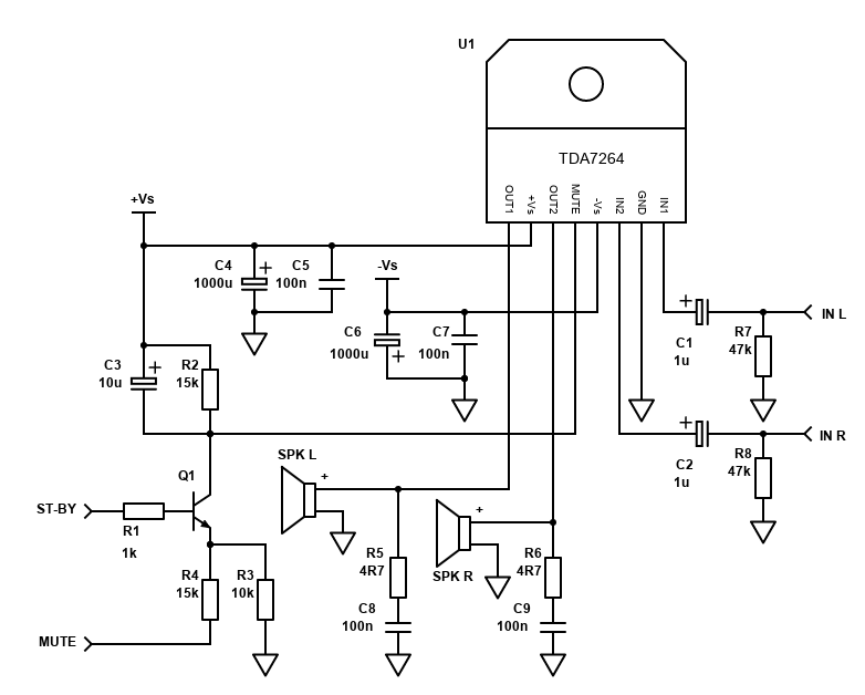
This amplifier is based on the typical application in the ST Microelectronics datasheet for this chip, but with a simplified standby/mute circuit so you don't need an external microprocessor or switches to enable the amplifier. The performance from this circuit is very satisfactory.
As this chip has a single row of pins (unlike the TDA7265 or similar), it is quite easy to build it on Veroboard / Stripboard PCB. Best results will be obtained by building use a custom PCB, but I have successfully tested an implementation on Stripboard.
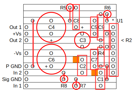
Be aware that Stripboard has limited track width and cannot take large connectors and currents of a high powered amplifier. The standard 2.54mm headers and DuPont connectors I use are also limited to a couple of amps, so I suggest you keep the amplifier somewhat within its maximum specifications if building on stripboard. Running off +/-17V (from a 12V AC transformer) into 8 ohms is as high as I've taken mine, but this will still give a pretty capable 14W (at 10% THD) stereo amplifier (as +/-17V will drop to around +/-15V under load).
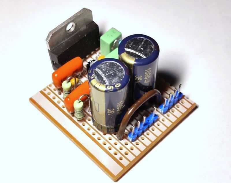
Below is a picture of the built amplifier on Stripboard:
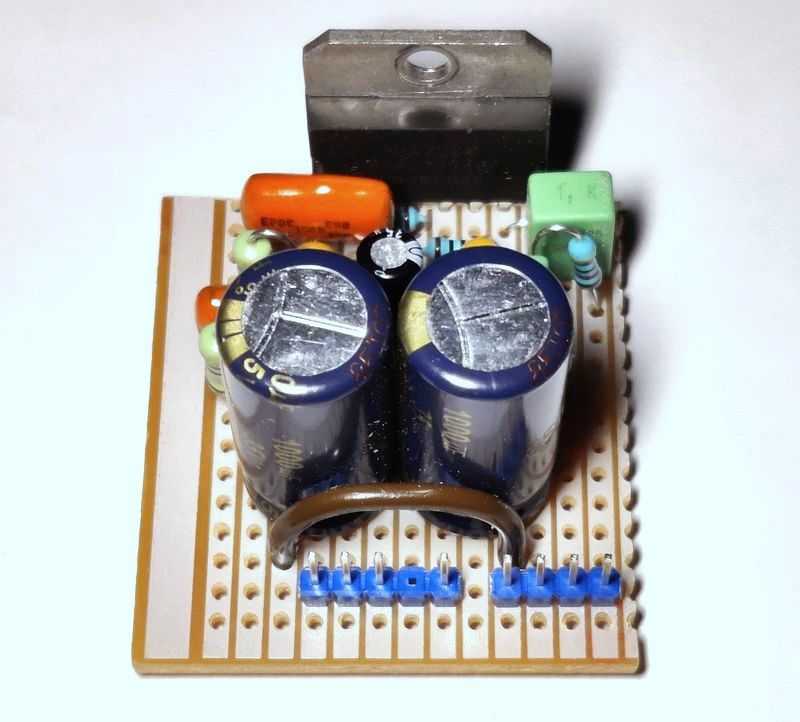
Note: Not shown, but a heatsink IS required!
A custom PCB will be better, and highly recommended if you are running the amplifier at a higher power supply voltage. Tracks may be laid out optimally and the PCB can be hand-made with minimal effort. The ST Microelectronics datasheet (linked above) contains a suggested PCB layout, or you can design your own and make it more compact for today's component sizes and the simplified mute circuit.
See my PCB Building Guide for a novice guide to drawing and etching your own PCBs using only cheap equipment.
Do note that with the datasheet layout, the board extends under the heatsink, so plan your design and heatsink purchase appropriately.
I've not designed my own PCB yet. That's because the Stripboard layout works quite well, and a custom single layer PCB will probably only be slightly smaller.
Components
| # | Type | Quantity |
|---|---|---|
| U1 | TDA7264 | 1 |
| R2,R4 | 10k ohm Resistor, ¼W Metal Film, 1% | 2 |
| R5,R6 | 4.7 ohm Resistor, 1W Carbon, 5% | 2 |
| R7,R8 | 47k ohm Resistor, ¼W Metal Film, 1% | 2 |
| C1,C2 | 1µF Capacitor, Polyester Film/Box (Best) or 16V+ Electrolytic | 2 |
| C3 | 47µF Capacitor, 35V+ Electrolytic | 1 |
| C4,C6 | 1000µF Capacitor, 35V+ Electrolytic | 2 |
| C5,C7 | 100nF Capacitor, 50V+ Ceramic X7R or MLCC | 2 |
| C8,C9 | 100nF Capacitor, 50V+ Polyester Film/Foil/Orange Drop (Best) or Ceramic X7R | 2 |
| In L,R | 2.54mm header 4-pin | 1 |
| +Vs,-Vs,GND | 3.96mm CH W2B Molex 5239/KK396 3-pin | 1 |
| Spk R,Spk L | 6.3mm Quick-Connect (Spade) PCB Disconnect | 1 |
| Heatsink, cable, connectors | ~ |
All resistors are recommended to be ¼W 1% metal film. The Zobel resistors (R5,R6) need to be minimum 1W resistors.
Input capacitors (C1 and C2) are best as 1µF polyester capacitors, which give a -3dB (half) cut-off frequency of 8 to 11Hz with the chips input impedance of 20k (min 15k). Electrolytic capacitors will also work.
Bypass capacitors (C5, C7) should be Ceramic or Multi-Layer Ceramic (MLCC). Zobel capacitors (C8, C9) are best as polyester, but ceramic will work too.
The rest of the capacitors are electrolytic. Their voltage rating must exceed one power supply rail - 35V is fine.
Ensure that electrolytic capacitors are connected the right way round - pay attention to C6 as the positive terminal is in ground, not -V supply.
Ceramic supply bypass capacitors (C5, C7) should be close to the IC pins.
Also added, but not mandatory, are R7 and R8. These resistors give a path for DC to discharge from C1/C2 or any capacitor on the output of a preamp (for example), without affecting the input impedance too much.
Do not run this amp without a good heatsink, it will get very hot very quickly and likely fail. Get a good heatsink, especially at high voltages, bridged or when driving 4 ohm speakers. The heatsink must also be insulated from the metal tab on the back on the chip, because this tab is connected to the -VS supply, not ground. This usually means mica washers, Kapton tape. Beware of Sil-Pads as they are often too thick and cannot transfer enough heat. Only if you are operating at low voltages can you get away with a small (medium-sized) isolated heatsink.
Do be aware that raising the power supply voltage raises the power dissipation. The heatsink should be large as dissipation can reach 21W when running from +/-20V - see figure 10 in the datasheet.
The gain is fixed at 30dB (typical). That's a voltage gain of 10^(30/20) = 31.6x. The gain is a reasonable value, if a little high as most amplifiers I build I aim for around 26dB. Still, you'll need a preamp to get to the maximum power as I was unable to drive it to its limits from a Smartphone. With no inverting input pin though, the gain cannot be altered, and nor can the amplifier be bridged without supplying a separate inverted input.
Speaker returns (-) should be both connected together at your PSU board 0V ground (after the capacitors), not the amplifier PCB. This is why my layout only contains the (+) speaker outputs.
Performance
After wired correctly, the TDA7264 makes a great amplifier. It could be considered Hi-Fi, thanks to its low distortion.
Power and distortion statistics are all listed in the datasheet and above. My recommendation is to match the amplifier to speakers of 8 or 6 ohm minimum. Though 4 ohm loads are possible, they are pushing the current capabilities of the chip except at low power supply voltages.
Mute/Standby pin 4
The TDA7264 includes a slightly cumbersome mute/standby pin that you cannot leave floating, tie to ground or tie to +VS (doing so will either make the amplifier silent or explode!). Connected directly to +VS, and the amplifier is in standby mode.
Basically, you need to bring the pin 2.5V below +VS to take it out of standby, and then 6V below +VS to unmute.
The easiest way to do this is with a voltage divider (R2/R4), with a capacitor C3 between +VS and pin 4. This way, when the power is initially supplied, the capacitor looks like a short before it charges, putting the amplifier in standby to begin with. Here's a simulation of the TDA7265, which behaves the same way:

As capacitor C3 charges, the voltage falls quite quickly 2.5V below, enabling the amplifier, and then 6V below +VS, taking it out of mute. This will take about 200ms and gives a pop-free start up.
With R2/R4 at 10k each, the voltage will eventually settle at ½ +VS, which should be fine if you are running voltages of +/-15V or more. At lower voltages, you'll need to reduce R4 to ensure the divider voltage is at least 7V below +VS (6V is 'typical', but 7V is the minimum difference needed).
If you're running off a really low voltage (the TDA7264 can work off +/-5V in theory), the voltage divider should be modified to reference between +VS and -VS instead of ground.
Microcontroller standby and mute
The datasheet shows several circuits suitable for connecting to a microcontroller.
You would need to start with the MUTE input high and ST-BY input low. This would put pin 4 to +VS.
Upon switching on, R3 and R4 enter the circuit. With R4 referenced to +5V, the voltage should drop between 2.5 to 5V lower than +VS.
When R4 is referenced to 0V, the voltage at pin 4 should drop at least 6V below +VS.
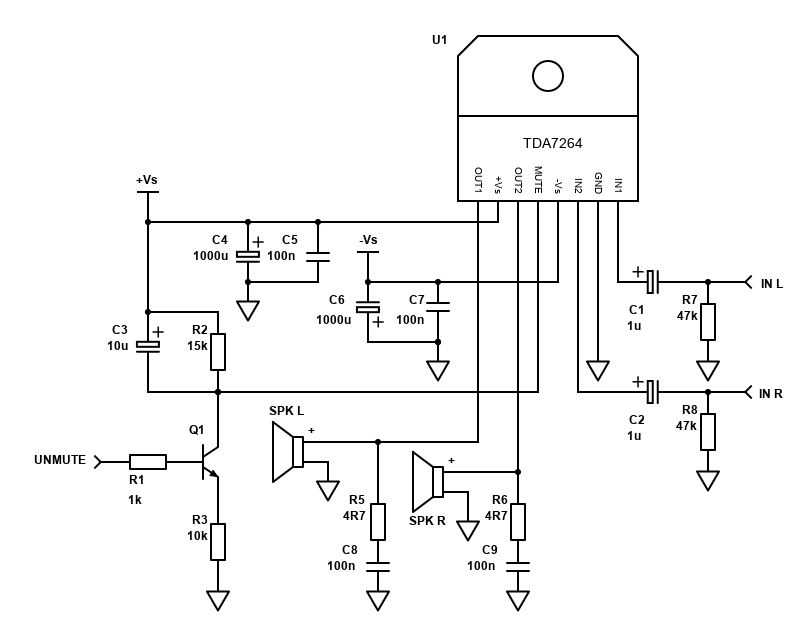
If you want muting only driven by a microcontroller, you could do it with the below circuit. Here, you would need to bring the mute signal voltage to 0V to un-mute the amplifier. High (5V) would be muted (but not in standby).
Power Supply
A power supply for this amp can be a simple split rail linear power supply, with a maximum voltage of +/-22.5V.
Wiring up a 2x 12VAC or 12-0-12 transformer will give +/-17V. This is great for 4 and 8 ohm speakers. 15VAC gets you to +/-21V, which is pushing the limit a bit, but gives you the maximum potential output into 8 ohms.
THE POWER SUPPLY REQUIRES MAINS VOLTAGE WIRING. DO NOT WIRE IT UNLESS YOU ARE SUITABLE QUALIFIED, DEATH OR SERIOUS INJURY MAY RESULT.
Your transformer size will depend on your amplifier, output voltage, and the number of amplifiers in your system.
For one TDA7264 amp, a 60VA transformer should be sufficient. You can get away with 40VA if picking a 12V AC transformer and running 8 ohm speakers.
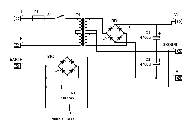
Capacitors should be 4,700µF minimum. 10,000µF si better (2× 4,700uF per rail is even better), rated at 35V minimum for +/-25V. You can only go for smaller voltage ratings if the unloaded voltage is comfortably below the capacitor's max voltage (for example 25V capacitors will be OK for +/-17V). Feel free to increase the capacitance but you may not get much additional benefit for the price involved. A fuse should be installed, I will leave it to you to work out what's appropriate because of the world-wide mains variations. Also be sure to correctly earth the supply and any metal casing around it.
The components on the earth and ground connections form a loop breaker. This is recommended construction because it can eliminate an earth loop. R1 is a 5W or better wire-wound resistor. The 100nF capacitor must be a Class-Y rated for 250V AC, you cannot use a 250V DC cap as it would fail open and burn if there ever was a fault causing mains to flow to earth. Check your country's rules and regulations before constructing this as it may be illegal. If so, omit all these components and connect the earth directly to ground but never disconnect the earth lead... it could save your life or somebody else's!
Grounding
The above schematic and Stripboard layout has all grounds tied together. This will work well when your power supply is separate from your signal source.
If, however, your power supply is also supplying current to a preamp or filter circuits as well as the amplifier, you may have a ground loop because the signal and power grounds are connected at the PCB of the amplifier and are also connected together at the power supply for the amplifier and preamplifier.
If you get hum or buzz because of this, you may benefit from separating the signal and power grounds at the PCB, either entirely, or via a hum breaking resistor of 10 to 22 ohms. Below is a modified Stripboard layout to support that. Rhr in purple is the hum breaking resistor. The PCB track below it needs to be cut.

As mentioned before, speaker returns (-) should still both be connected together at your PSU board 0V ground (after the capacitors). The power ground from the PCB returns to this exact same point too.
The signal ground will connect to your preamplifier circuits, or common preamp ground star. This preamp star must also be connected to the main PSU via another path.
Bridging?
As the feedback network is internal to the chip, this amplifier cannot be easily bridged. The TDA7265 is easier to bridge, so consider this chip instead, however, if you do want to bridge the TDA7264, it can still be done.
You'll need to provide the normal input to IN(L) and an inverting input to IN(R). The speaker + would connect to OUT(L) and - to OUT(R), if phase matters.
If bridged, this amplifier can provide a mono output into 8 ohms only. Do not consider bridging into 4 ohms.
Even into 8 ohms, keep the power supply below +/-16V (i.e., from a 12V AC transformer) and it should give 50W at 10% THD. Make sure the amplifier has a big heatsink.
Some sources might already have a balanced (normal and inverted) output, but the majority are unbalanced meaning we have a signal and a return (on ground).
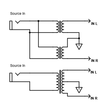
To create the inverted signal, you can either use 1:1 ratio transformers (i.e., 600:600 transformers). A centre tapped one will give both the original, inverted and return ground. Alternatively, two transformers can be used where the inputs of each would be in parallel with the source, the output would be connected to each TDA7264 input mirrored from each other. This is illustrated below (the top connection of L1 gives the non-inverted signal to the left amp, the bottom connection of L2 gives the inverted signal).
Transformers do affect audio quality though and will drop some low frequencies (bass). You'd also need two centre capped, or four without the centre tap, for a stereo BTL configuration, and this will cost some pennies and take up a fair bit of space! Examples of both is shown below:
An alternative is to use an op-amp to invert the signal to the second input. ESP Project 14 - Bridging Adapter is the solution here. You'll need 7812/7912 (+/-12V) or 7815/7915 (+/-15V) regulators to bring the PSU voltage down to a level for the opamp.
Alternatively, for another way to provide high power output, consider bi-amping instead. This would require a speaker cabinet with two woofers (bass and mid). With a crossover frequency of around 275Hz, you'll get the same 4x output capability, so long as your speaker has two woofers able to cover above and below that frequency and you can build an active crossover.
Single supply? - No
The TDA7265 datasheet has single supply suggestion, but the TDA7264 datasheet does not have such a suggestion.
I tried implementing a single supply version by connecting pin 7 to ground via a 100µF capacitor, connecting -VS to ground and putting large capacitors in series with the speaker outputs.
It kind of worked, but with low power. With a DC single supply of around +34V, I saw a DC offset of only 5V at the speaker outputs, meaning the negative peaks of the wave were clipped after about 2.6V RMS. This makes it useless because you could pick a smaller and more efficient amplifier for quite a low output.
This means internally, the GND pin 7 is perhaps not quite the same as the GND pin 9 on the TDA7265, which does have a single supply suggestion. I did try using a voltage divider and applying that to the L/R input pins to try and improve the situation, but whilst this improved the situation, the DC offset at the output was still far short of half-way (9V when it should be 18V). Maybe adjusting the divider to give a higher offset would work, but only for a certain power supply voltage and it feels too much of a hack to continue further.
Therefore, giving the lack of success of the single supply test, I don't recommend you build it and if you're looking for a single supply stereo amplifier, the TDA7265 is the closest alternative, or if you are happy with bridged outputs, the STA540 / TDA7375 chips are also good.
Conclusion
The TDA7264 is still available today, and is great for building a medium power, but pretty capable Hi-Fi amplifier.
It has replaced my two separate TDA2030 amplifiers in my small room amplifier, which powers a set of cheap and small JVC mini system speakers on the bookshelf and is my ironing stereo, because it's oriented and placed where I stand and do clothes ironing!
This amplifier is powered off a 12V AC transformer (gives about +/-17V), which also powers a tone control and bass boost circuit. Together with a phone or tablet, it's great for a small session of radio or music listening. Runs cool and happily.
As there are two amplifiers on one chip, it does allow you to make a small stereo system (even on Stripboard), or a pretty powerful mono bridged amplifier. Though my builds were on Stripboard, they worked and would be adequate for a simple project capable of giving you a decent quality sound system. A custom PCB would be better still, especially if pushing the TDA7264 to its limits.