
PIC Microcontroller USB Mouse Jiggler Keep Awake using PIC18F2550 / PIC18F2455
Introduction
Here's a custom project using parts I already had to 'fake' simulated mouse activity to any PC/laptop that has USB 2.0 or better.
I've built this for a kind of naughty reason and that's because many corporate laptops I use have an aggressive screensaver timeout, where 5 or 10 minutes inactivity means you'll be entering that long or complex (usually both) password they require several times. I get it... 'security first' is especially important when in the office, on transport or cafes (honestly, I never do the latter though).
These days, changing the screensaver timeout is disable by group policies, so you're stuck! When working from the security of your own home though, a 5 minute timeout is unnecessary, and when all I want to do is monitor that device for emails or IM chats, having it lock in 5 minutes is a pain!
The best habit - one I've known since my late school days (as long ago as the year 2000) is the keyboard shortcut Windows+L - instantly locks a device.
There's probably a software solution that will work, but installing software could get you in trouble. USB mouse jiggler / wigglers can be brought. I had a spare PIC18F2550 though which has built in USB support, so I decided to look for some code and make my own device, which won't even cost me anything!
My requirements are simple - make it move the mouse and turn it on or off via a push switch / button. Additionally, have a timeout which stops the simulated activity after a set time, just in case I leave it on.
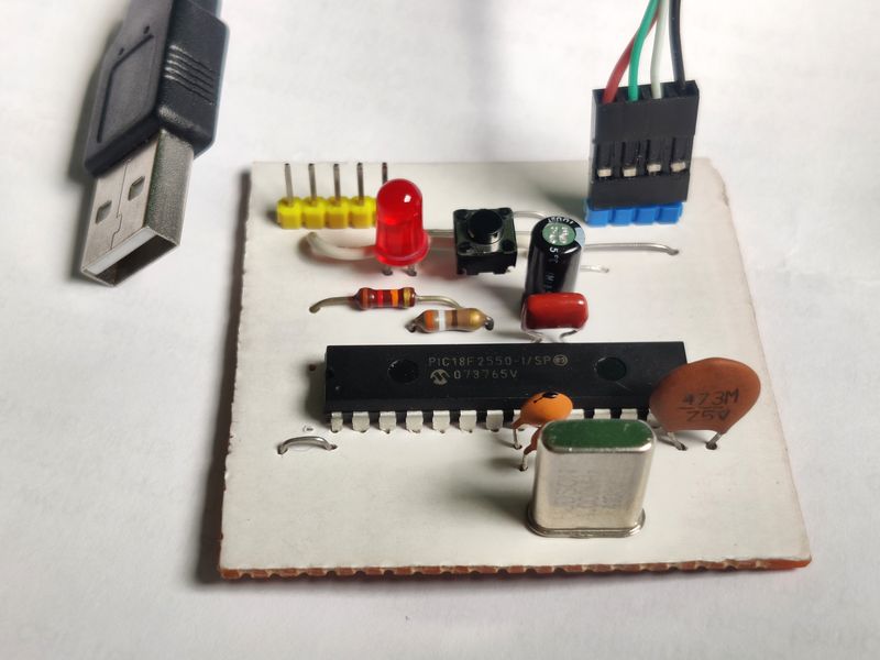
Beyond the PIC18F2550, all that's needed is a crystal and loading capacitors, a momentary switch, LED, headers and a few other common capacitors and resistors.
Below is the schematic.
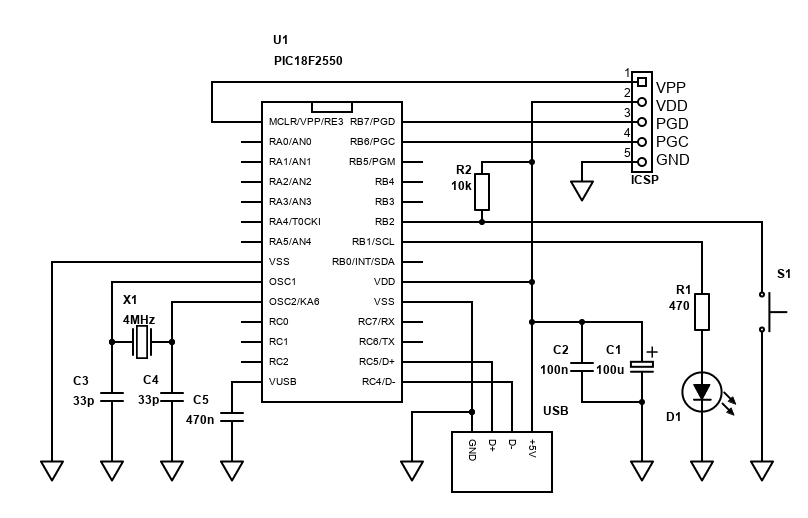
The heart is the PIC18F2550. A PIC18F2455 will also work. The larger PIC18F4455 and PIC18F4550 will work too, but you'll need to adjust the layout as these are large 40-pin microcontrollers.
X1 is the crystal. I used 4MHz as I have lots of these old crystals. Most projects use a 20MHz crystal, which I didn't have. There is flexibility on the crystal choice, and you can look at TABLE 2-3 in the datasheet (page 29). Basically, there is a PLL frequency multiplier that produces 96MHz from 4MHz. The USB clock of 48MHz can then be derived from that, and likewise the microcontroller frequency.
With a 4MHz crystal, no division is required for the PLL - PLLDIV2:PLLDIV0 are all zero. With 20MHz, you need to divide by 5 (20 × 24 = 480, ÷ 5 = 96). The microcontroller frequency target of 24MHz is 96 ÷ 4, set with CPUDIV1:CPUDIV0 set to 1 and 0.
The crystal must be loaded with two small capacitors C3 and C4. 27pF or 33pF works fine for 4MHz. Use 15pF for 20MHz. The capacitors and crystal should be physically close to the microcontroller.
The switch S1 is a momentary push-to-make switch (aka. button), connected to port RB2. The 10k resistor R2 pulls the input high when the switch is open. Pushing it closes the switch and pulls the input to ground hence active = 0. You may spot I used a 12k resistor - I have a tons of them! +/-20% is fine.
LED D1 lights when jiggling. Mine is a really old junk red LED. The current is limited by R1 (470 ohms, though I ended up using 390). This makes it visible but not too bright. You always need to current limit LEDs, and if driving directly from the microcontroller's pin like this, the maximum current is 25mA. With 390, the current should only be about 7.7mA, calculated as (5 − 2) / 390 (where 5 is the supply voltage, 2 is the LED forward voltage) - easily safe.
The remaining capacitors are bypass/stability caps. C1 and C2 are across the USB 5V supply. C2 is a ceramic capacitor and should be physically close to the microcontroller. C1 is an electrolytic - 100µF and at least 10V. It must be oriented so the + pin (usually the longest lead, but check the package is in the +5V VDD line). C5 is needed for the internal 3.3V voltage regulator (as USB D- and D+ lines use this voltage). I used a really old 470nF ceramic capacitor from my stock and it works fine. A correctly installed electrolytic would do too.
This circuit is easily built on stripboard, and there's little point in making or ordering your own PCB. Once cut, the board size is 50 x 50mm. Below is my layout.
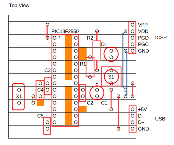
If using this layout, take note that the orange squares indicate areas where the strip needs to be cleanly cut. You also need five jumpers, which can be offcuts from the resistor or capacitor leads. The blue jumpers are insulated wire jumpers as they're a bit too long to be offcuts.
Also needed is a USB cable. I have lots of spares, so I just cut the micro-b port off the end of a cable, stripped it and crimped a 4 pin DuPont connector to the 2.54mm header. On my cable, green was USB D+, white was USB D- (along with the expected red for +5V and black for ground). Test though because the standard differs!
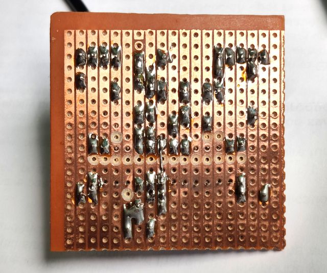
Below is a picture of my quickly soldered build.
A programmer is needed to burn the program onto the PIC, I use UsbPicProg for that and have a dedicated ICSP (In-Circuit Serial Programming) header on this board for easy re-programming.
The program is available on github.com. This builds on the BoostC example code - specifically usbtestcc.c and usb_defs.h by Robert Lang (building on the work of Reston Condit, Dan Butler, Andrew Smallridge).
Current memory usage is 4634 bytes of the ROM and 326 bytes of RAM, leaving plenty of free memory to expand capability if desired.
I've cleaned up the code and adjusted / simplified it a bit for my own purposes, but I haven't really got down to the details of how it works as understanding USB is new to me. Figuring out how the code works is quite a job for another day perhaps.
What I have done is used the timer to debounce the push switch, and added a timeout timer that deactivates the jiggle after a hard-coded time (currently 30 minutes, see JIGGLE_TIMEOUT in PICUsbJiggler.h).
Here's what it does, once the button is pressed:
No drivers are needed on Windows or Linux (and probably not for Mac either).
References:
- Source code on github.com
- PIC18F2550 / PIC18F2455 datasheet
- SourceBoost Technologies - low cost, high performance cross compilers
- UsbPicProg - Open Source Microchip PIC programmer
- SourceBoost Example Code usbtestCC.c by Robert Lang
- Dring Engineering Services - IC Timer Calculator and Source Code Generator
- Hackaday - Embed With Elliot: Debounce Your Noisy Buttons, Part II
- RomanBlack.com - Zero-error 1 second Timer