
PIC Microcontroller Aquarium Control with DS3231M, DS18B20 and TM1638
Introduction

I've had a small aquarium since 2013, but a recent thermometer failure and thinking about how many times I've manually activated lights at inconsistent times triggered this project idea.
The aquarium is a Love Fish 64L tank, which looks quite big, but really, it's the smallest tank you can get away with to keep a few small fish healthy with aid of the nitrogen cycle and live plants. That's even after upgrading the weak internal filter with an external one and topping the water via a Pozzani Nitrate filter, since East London water is very high in nitrates straight from the tap (and very alkaline, for water). I do 24L of water changes every 3 weeks, ignoring the useless timer that comes with the tank, but I digress...
Being a small tank means the temperature should be kept stable for the benefit of the fish, so I installed fans in the lid which reduces water temperature via evaporation.
The LED lights in the tank are quite good and give off plenty of light for low power. They are powered off an inefficient AC-AC adaptor and an LM7812 linear voltage regulator though. The AC-AC adaptor is intended to power the internal filter too, but I'm not using that.
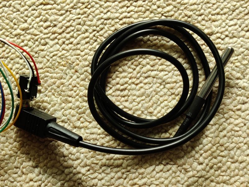
I brought a waterproof DS18B20 some time ago which would be ideal for temperature monitoring. With a couple of MOSFETs (and a relay), I could also use the temperature to trigger both heating (although I don't have this since I'm currently keeping temperate fish) and fans.
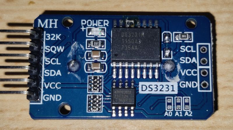
I also brought a DS3231M module, which I used for timer based experiments. This is an ideal basis for a clock (and a pretty accurate one). With a clock, I can then trigger the lights to go on and off at appropriate times of the days.
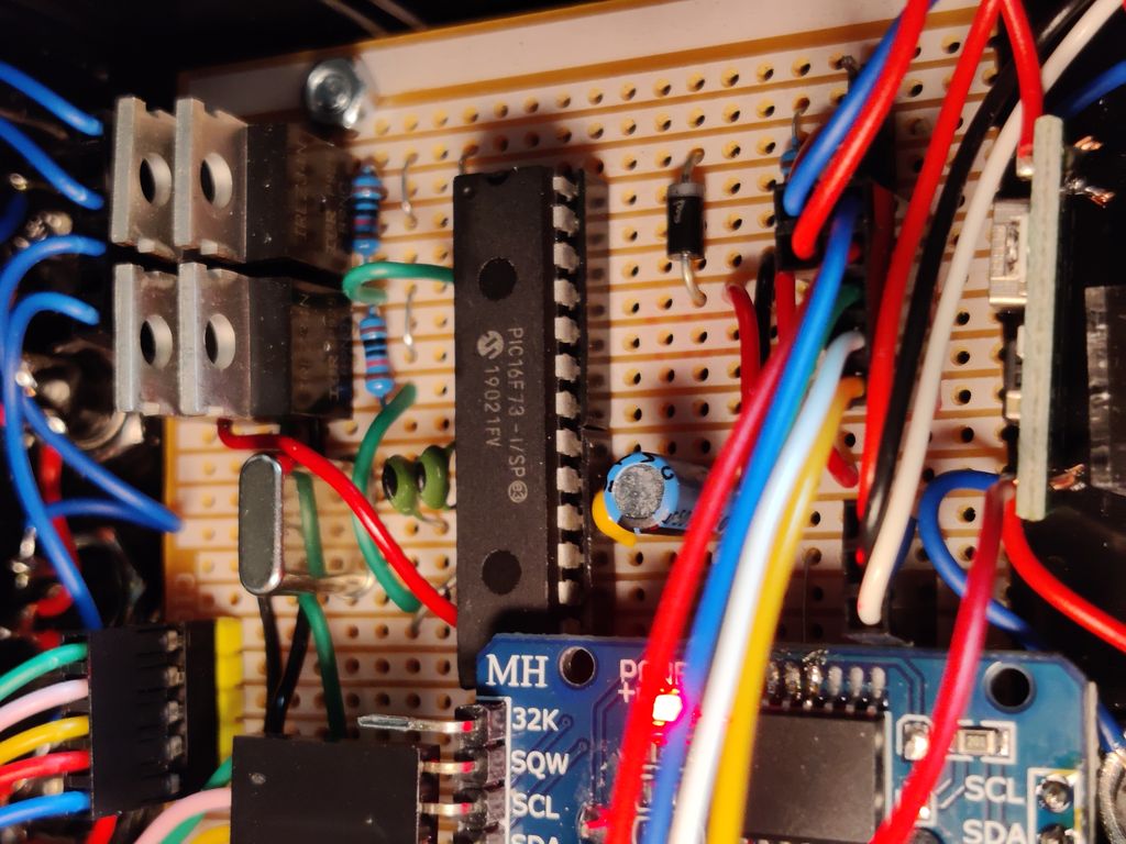
Note the removed diode, so I can use a standard (non-rechargeable) CR2032 3V backup battery.
There's scope here to also expand the project to do PWM brightness for the lights, or trigger a food feeder, but I've not done those here as I'm not sure what PWM frequency is good for the tanks LED lights and the effect on the fish (who can detect flicker at higher frequencies than us, especially when deeper in the water).
All I needed was a central microprocessor and a human computer interface in the form of a display and push buttons.
I have a few PIC microcontrollers, and I started the program with the PIC16F628, but I found it too much of a challenge to fit all the features I wanted in 2048 words of program memory, hence building on the PIC16F73.
The PIC16F73 were mistake buys for another project when I forgot they don't contain EEPROM. This project doesn't need it on the microcontroller because the DS3231M module has an AT24C32 EEPROM built in. With 4096 words of program memory and 192 bytes of RAM, that's enough for my needs (my program uses 2687 words and 104 bytes of RAM).
The gap here was the display and buttons. I'm not a fan of LCD displays as they are hard to see from afar, and I wanted to be able to see the temperature and clock clearly, and whilst there are now bigger OLED display modules available, they are quite expensive. This means I'll go with old fashioned 7-segment LED displays, since I'll mostly be displaying numbers.
I'll also need buttons, to manually turn on/off lights if required, as well as setting the time/date, and light trigger times and fan/heater trigger temperatures.
Whilst it's possible to use the PIC to multiplex the 7 segment displays directly, as well as scan for button presses (via an ADC is best), it's quite some PCB work and a coding challenge too as those displays will flicker when the processor needs to do other work.
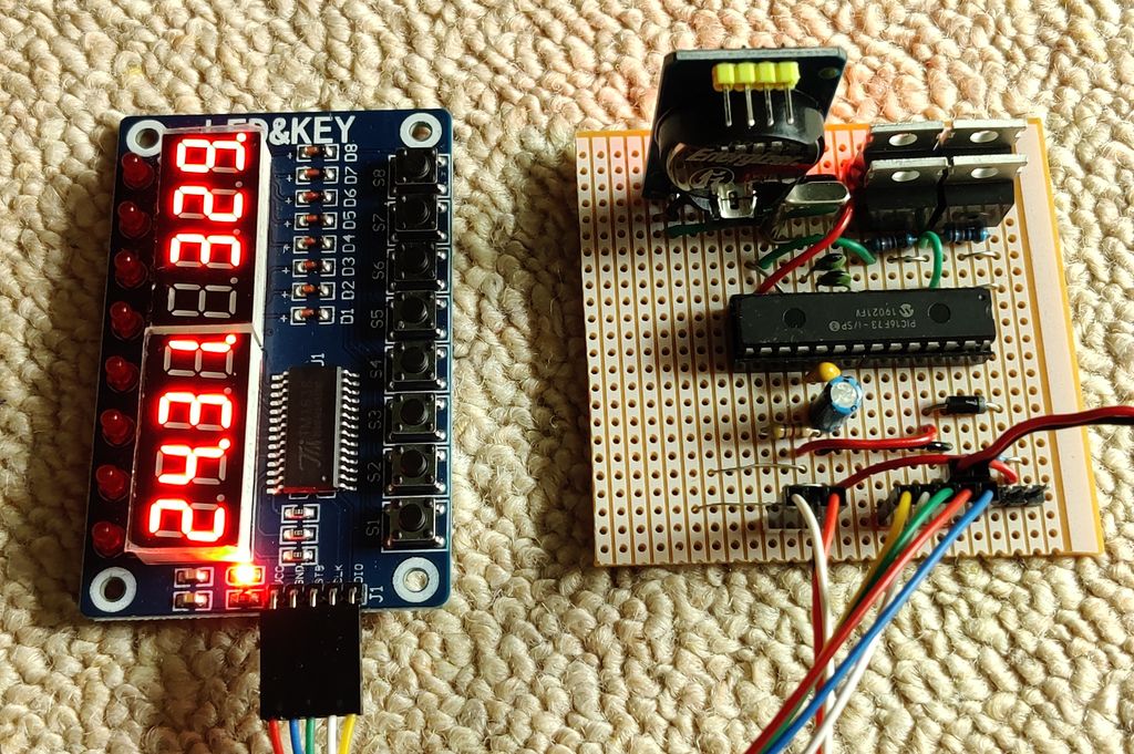
So, I looked for a module to handle this for me and found the TM1638 is ideal - 8x 7-segment displays, 8x LEDs and 8x buttons, all readable/writable via an SPI-like interface (which I can bit-bang in code).
Schematic
The schematic is below. It's fairly simple; there's 4x MOSFETs to trigger the fan, heater (via relay), white and blue LED lights on and off.
The TM1638 is connected to the PIC via its own 3-wire SPI-like interface, DS18B20 to one port (with pull up resistor) via it's one-wire interface and DS3231 module (which has the DS3231M and AT24C32) connected to 2 ports via the TWI/I2C two-wire interface. That's three different interfaces in total - not ideal design, but it's making use of the modules I have and are available cheap.

The PIC16F73 does not have an internal oscillator, so a 4MHz crystal is used (with 33pF loading capacitors). Support for in-circuit serial programming (ICSP) is also provided.
The schematic is simple enough that I decided to do a design and build on standard Stripboard. This makes it more accessible to hobbyists who don't have the ability to create custom PCBs but want to learn how to build circuits and solder.
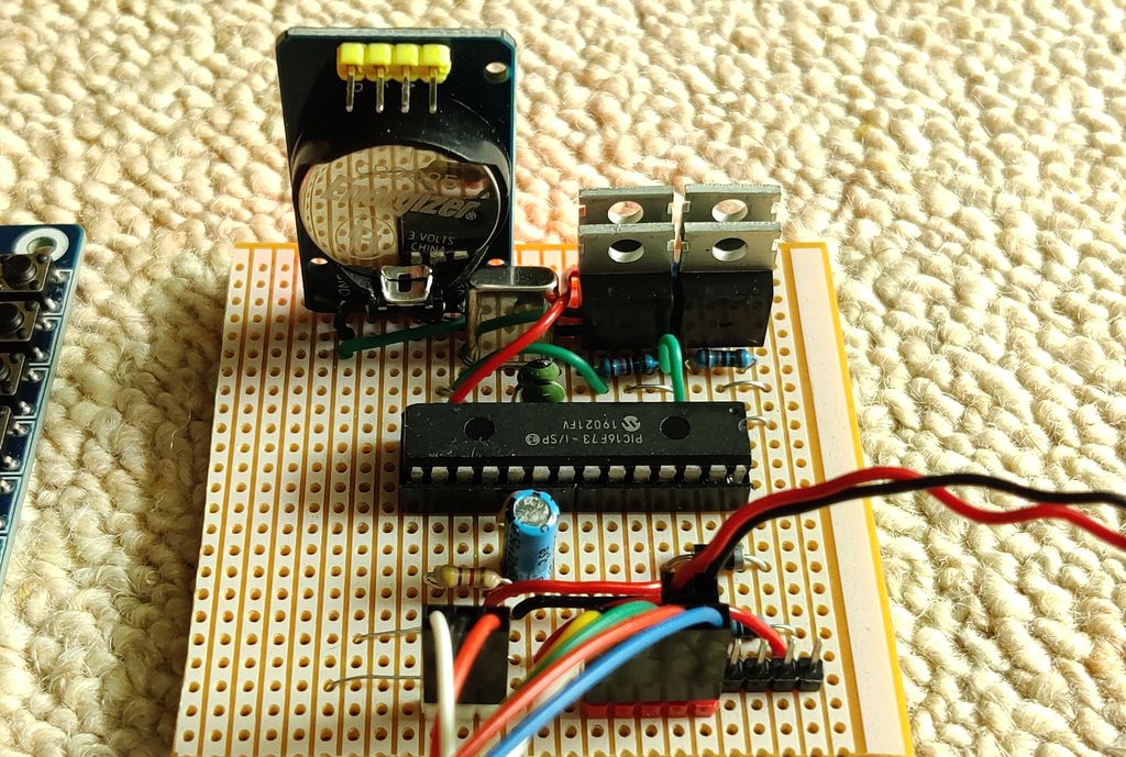
The MOSFETs I used are logic level compatible N-Channel IRLZ34N, but more common alternatives like RFP30N06LE or FQP30N06L are also suitable. If you use the same PCB layout as me, the pin order from one to three must be Gate, Drain, Source.
Capacitors C2 to C4 should be ceramic X7R or MLCC capacitors, and physically should be positioned close to the PIC microcontroller. Capacitor C1 should be a standard electrolytic capacitor, somewhere between 33µF and 220µF with a voltage rating of 10V or higher. Make sure it is installed the correct way round.
Resistors - standard ¼W carbon or metal film resistors. One 4.7k and five 10k resistors are required. The crystal is a standard 4MHz crystal. Faster ones will also work, but you'll need to adjust the program and probably reduce the pF values of C3 and C4 (the datasheet will suggest values).
Diode D1 is a standard 1N5817 Schottky (so forward voltage drop is minimal). It's there for preventing the ICSP programmer from powering all the peripherals.
Below is the stripboard/Veroboard layout I came up with. Quite a few jumper wires and track cuts are required but the result is quite compact, and it wouldn't be that much smaller on a custom PCB mainly due to the size of the microcontroller.
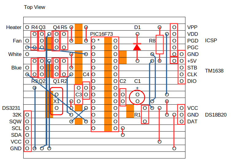
Orange squares indicate where to make cuts. Red lines are either components or straight jumpers that can be made from offcuts of resistor/capacitor legs. Blue lines are insulated wire jumpers.
All headers are standard 2.54mm pitch headers that accept so-called DuPont connectors. I made my own cables as I have a kit and crimping tool (these are worthwhile getting for any hobbyist). The DS3231M can be soldered directly to the board via its own header which I started off doing, but then change the layout and mounted it separately via a cable as it was too tall to be mounted vertically in my project box.
Note that ICSP and power share one-pin of the same header, which forces you to unplug the power supply before programming.
You may spot that two DC voltages are involved here. 5V is required for the PIC16F73, TM1638, DS3231 and the DS18B20. 12V is required to power the aquarium LED lights, 12V DC computer fans for cooling and optionally a heater which would be switching via a 12V relay.
It's easiest to run just one DC power to the whole system, so I'm using a 1A 12V AC-DC adaptor from the drawer of spare ones (it's a switching adaptor, so efficient). To get 5V, I'm using a MP1584 DC buck convertor to get the 5V required. This regulator is small, cheap and efficient and whilst it's quite noisy for some applications, it doesn't matter at all here.
Ground is shared for both 5V and 12V voltages. It needs to be for the MOSFET switches to work. I take a single ground wire from the output of the MP1584 to the control board, where it jumps around a few tracks to connect all the peripherals, but it does not loop back to itself, helping avoid any odd behaviour from bad/noisy grounding.
The capability to switch on/off a heater via a mains rated 12V relay is there in case I put tropical fish in there, and the temperature read by the DS18B20 will be more accurate to control water temperature than the built in thermostats these heaters usually use. If you do use this feature, the relay should be in a separate box in-line with the wire to the heater. Mains wiring would be required here, so you must be qualified and competent.
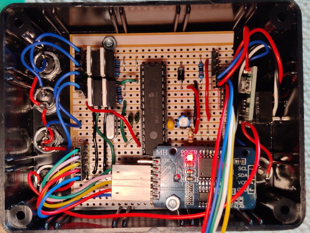
Below are a few pictures of how it turned out and mounted in the project box.
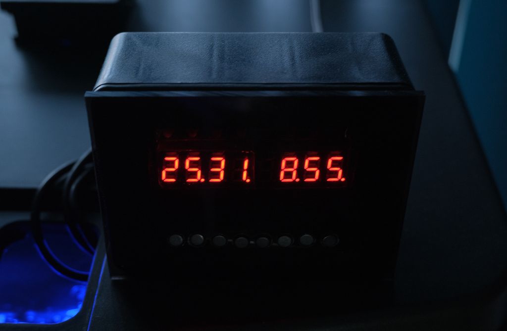
These pictures show how I mounted the components inside the ABS 100 x 75 x 40mm project box - a tight fit, but it worked out well. The TM1638 (not shown) is mounted on the box lid. Tucked on the side is the MP1584 buck step down regulator, set to 5V output for the PIC and peripherals.
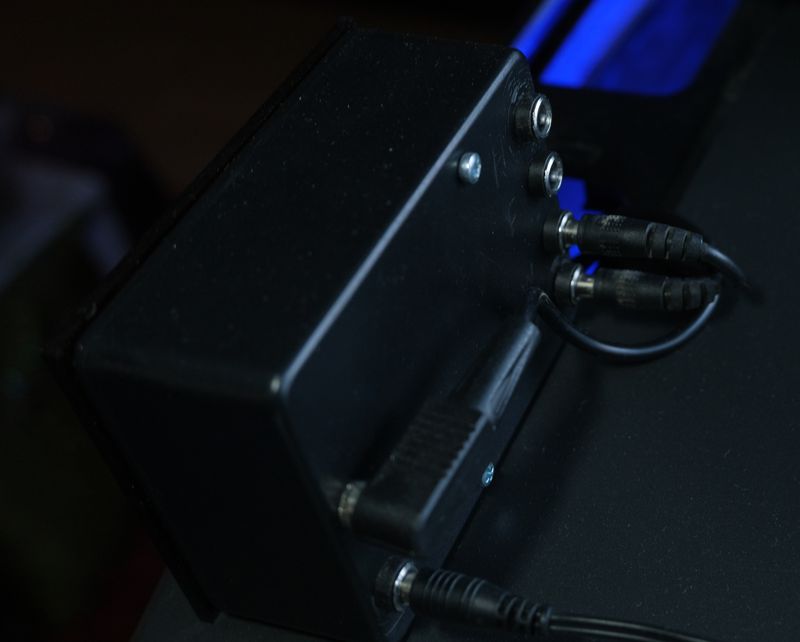
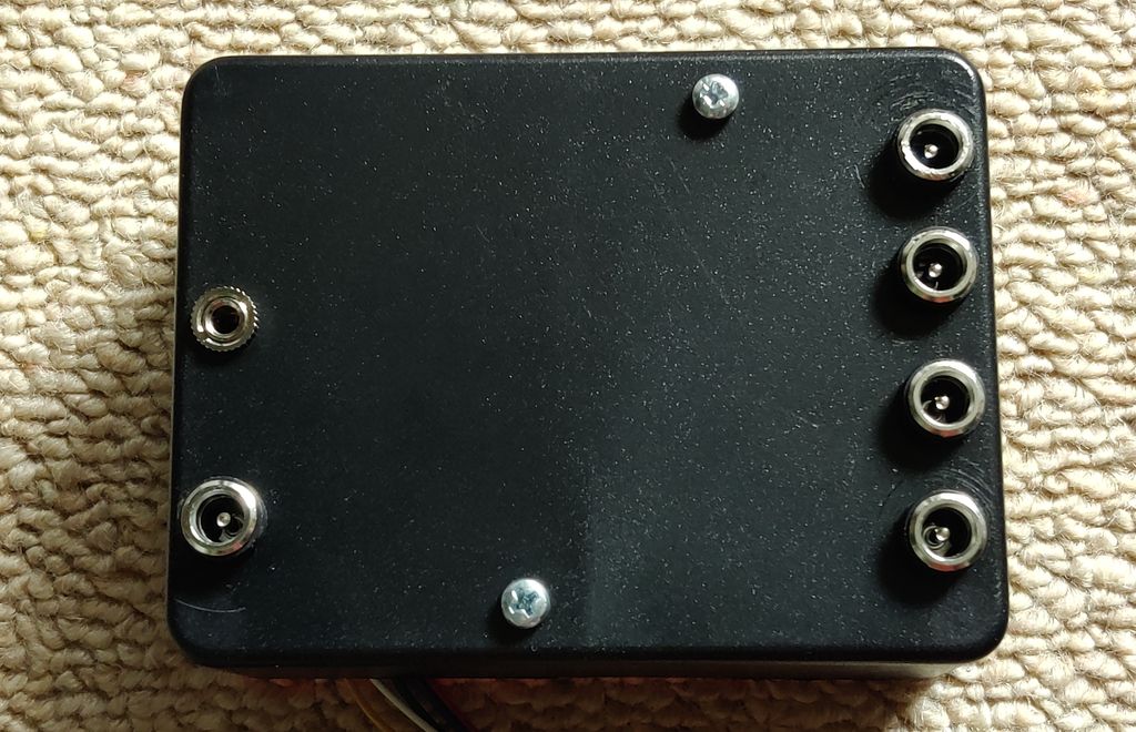
Below is a picture of the back of the box. On the left is a 3.5mm stereo connector which I used for the DS18B20, the main 12V DC in 2.1mm barrel connector. On the right are four 2.1mm DC barrel connectors for 12V triggered outputs - White LED, Blue LED, Fans and Heater (via an external 12V relay).
Code and Demo
The code is on github.com. This is built using SourceBoost with the BoostC compiler, which is now donation-ware so you can clone my repo and use and modify the code to your needs with this great IDE and compiler, all for free, but please donate if you like it.
My requirements started small but grew a little more once I changed the PIC microcontroller to the PIC16F73 as I had more program memory available to use.
Therefore, what has been implemented is:
- A thermometer that can request and read the water temperature from a DS18B20 every 30 seconds and display it in Celsius (to 2 decimal places) and Fahrenheit (to 1 decimal place).
- A clock that keeps time accurately (so an RTC, real-time clock) and can display the time in 12h format, 24h format and optionally display the date (day and month)
- An on/off trigger for the main white LED aquarium light. On hour and minute, and off hour and minute
- An on/off trigger for the blue LED aquarium light. On hour and minute, and off hour and minute
- A second on/off trigger for the blue LED aquarium light. On hour and minute, and off hour and minute (allowing the blue light to come on twice a day.
- An on/off trigger for the hood fans. Switches on once the water temperature exceeds a threshold, and off once the temperature drops below a threshold.
- Manual triggering of lights and fans
- An on/off trigger for a heater (though I don't have one currently, it seems a sensible to build it). Switches on when the water temperature drops below a threshold, and off when the temperature reaches a threshold.
- The clock should be set from the device itself - this means setting the year, month, day of month, day of week, 12h/24h format, hour and minute (seconds get set to zero after applying)
- The trigger on/off times and temperatures should also be set from the device itself
- Remember the trigger settings and time after power loss
- Since the RTC contains the full date, automatically adjust the time twice a year when daylight savings time starts and ends
The code is working well, but there are a few things I did not implement:
- PWM light brightness. The PIC is capable to do this, but the software would need updating to allow the user to set brightness via buttons. The main reason I've not done this though is I don't know how the Danios and Platys will react to PWM flickering, or how well the existing LED bulbs will cope with high PWM frequencies.
- There's only one white light on/off time per day, and two blue light times. That's fine though, in real life, the sun only comes up once a day too!
Comments in the code generally explain what's going on, so I won't explain in detail what each function is doing. The video below shows the result and how the system works when setting time/date and trigger on/off times/temperatures.
Conclusion
This was one of my shorter projects as design and soldering and build time did not takes more than a couple of evenings. The code took longer, but again a few evenings over a month.
It's something I should have done years ago. It works reliably and with this and my automatic feeders, the aquarium really takes care of itself until water change and filter change weekends!
References:
- Source code on github.com
- PIC16F73 datasheet
- DS18B20 datasheet
- TM1638 datasheet
- SourceBoost Technologies - low cost, high performance cross compilers
- UsbPicProg - Open Source Microchip PIC programmer
- Dring Engineering Services - IC Timer Calculator and Source Code Generator
- Learning about Electronics - How to Connect a In-Circuit Serial Programming (ICSP) Interface
- SourceBoost Forums - DS18B20 one wire reference for SourceBoost
- Peter H. Anderson - DS18B20 SourceBoost implementation, including ds18b20 to Celsius x100
- Electro-Tech-Online - Temperature Sensor DS18B20 Display Fahrenheit, ds18b20 reading to Fahrenheit x10
- Electro-Tech-Online - PIC Single-Chip 4-Digit DS18x20 Temperature Monitor
- Circuit Digest - Digital Thermometer using a PIC Microcontroller and DS18B20
- Handson Technology - TM1638 User Guide
- JetPackAcademy.com - TM1638 Cheat Sheet
- PICLEARNING.net - PIC and TM1638 LED&KEY module
- Last Minute Engineers.com - Interface DS3231 Precision RTC Module with Arduino
- Instructables - The Most Comprehensive Guide to Programming the AT24C32 / AT24C64
- Github.com - Adafruit RTClib