
BA5417, BA5406 DIY Guide - 5W Stereo Single Chip Power Amplifier
Both the BA5417 and BA5406 are discontinued amplifier chips now, although the BA5417 was still available at my supplier in July 2020, it's now no longer available. The BA5406 is harder to find. Be wary of fakes.
Both chips allow you to build a simple stereo amplifier, or a bridge mono amplifier. The BA5417 must have a PCB, however the BA5406 can fit on stripboard.
Recommended Experience : Beginner to Intermediate, knowledge of amplifiers, heatsink attaching, custom PCB needed
BA5417 application
Quick facts BA5417
- Power output: 5W + 5W into 3 ohms at 10% 1kHz distortion with power supply 12V
- Power output: 6W + 6W into 4 ohms at 10% 1kHz distortion with power supply 15V
- Power output: 3.5W + 3.5W into 8 ohms at 10% 1kHz distortion with power supply 15V
- Power output: 2W + 2W into 8 ohms at 10% 1kHz distortion with power supply 12V
- Power output: 12W into 8 ohms bridged at 10% 1kHz distortion with power supply 15V
- Gain: 45dB per datasheet, 32.5dB for my suggestion, variable
- Power supply: 6V to 15V single supply
- Class AB
- Datasheet available here
Guide
The BA5417 is a simple to build stereo/dual amplifier that is a step up from the LM386 or other small amplifier chips that allows you to deliver a fair amount of volume into a pair of speakers from just a single supply voltage source.
Despite being available until 2020, it's actually really old and its intended use is for radio cassettes. There are a range of possibilities though:
- It is a capable amp for a stereo system (i.e. a homemade or upgraded midi system or 'ghetto-Blaster')
- PC speakers
- TV audio
- Stereo, Bi-amplified or Mono Bridged Bluetooth speaker
This amplifier is based on the typical application in the ROHM Semiconductor datasheet. The performance from this circuit is fairly decent. The data sheet is far too shy of telling you what the power output is at 1% THD across a variety of voltages with typical speaker impedances of 8 or 4 ohms. It does tell us into 3 ohms, the 1% distortion at 1kHz power output with a supply voltage 9V is about 1.1W (figure 21). Output into 4 ohms will be a bit lower, and 8 ohms a lot lower (expect only a little over 0.5W at 9V).
I've seen ghetto blaster speakers around 3 ohms before, which seems to be what the BA5417 targets, but it's unlikely you'll be able to buy speakers of this impedance, so look for 4 ohm speakers. In BTL mode, the best output is in to 6 ohms, and these are a little more common but still may be a challenge to get. 8 ohms will work fine though too.
The standard datasheet application has the gain for the chip is configured as 45dB, which is huge! That's a voltage gain of 183 times! It does not imply that the closed loop gain is variable, but fortunately it is by changing the 120 ohm resistors (RF1 and RF2).
I suspect the high gain is because it's expected to amplifier a weak output from cassette players or AM/FM radios from those days, but unless you know you need that elevated level of gain, I suggest you use my adjusted circuit instead which will give a more reasonable gain of 40x (32dB), and this will improve the signal to noise ratio considerably.
The initial appeal of the BA5417 to me was the simple single-in-line pins. It looked ideal for building quickly on stripboard/breadboard, but I should have checked the datasheet before buying because unfortunately the pins have a spacing of 2mm, not 2.54mm (0.1 inch) spacing that standard prototyping board has.
If you're building a new project and don't already have this amp, consider the TDA7297 / TDA7266 chips instead. They are better performing (as they are already bridged by default) into 8 ohms, require less components and the fixed gain is more reasonable. If you need 4 ohm capability, the STA540 / TDA7375 or similar can be considered instead. Its circuit is almost as simple as the former, and still much simpler than the BA5417. All these chips can be built on stripboard if desired.
For those whose application really doesn't need a dual/stereo amplifier (and bi-amplification would not be any consideration), there is a mono alternative TDA7266M or TDA7391 to name two. The BA5417 can be configured in BTL for a mono speaker, but the TDA7266M or TDA7391 are both simpler circuits.
Whilst all these amplifiers are more expensive than the BA5417 (the BA5417 is really cheap!), the overall cost will be about the same because there are fewer external components.
Circuit
There are two types of application for the BA5417.
- The single ended application (aka OTL)
- The BTL application
Single-ended (OTL) application
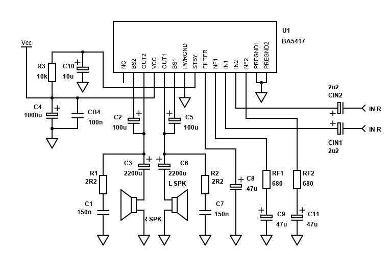
The single ended / OTL application is the standard stereo configuration for the amplifier. It is able to drive speakers down to 3 ohms in this configuration, or 4 ohm speakers with a headline power output of 6W (per channel).
Only one chip, and numerous components are needed for a complete stereo system, and the single ended application shown may give enough power for your needs. This application is designed for running off a single rail power supply only, such as batteries or common DC power packs.
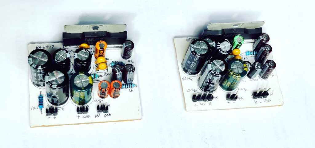
The BA5417 has to have a custom PCB because the pin spacing is too narrow to fit in stripboard or breadboard. My PCB Building guide has information on how you can draw and etch a custom PCB. The layout below shows an example I built and tested.
This is my hand drawn style that can simply be reversed and drawn as a copy onto single sided copper board. The DPI of this image should print to the exact size you need, which is 50mm x 40mm. Measure carefully the pin holes for the chip though as each pin is exactly 2mm apart and this is critical because the pins will not flex much.
The final PCB ends up being fairly large mainly because of the requirement for DC blocking capacitors (C3/C6), but because the chip also needs external components for stability such as the Zobel network (C1,R1/C7,R2), bootstrap capacitors (C2/C5), filter (C8) and decoupling capacitors (C4,CB4).
Despite this, it's still quite reasonable and compact. A stereo fully discrete transistor amplifier of the same power would be larger.
Note that I'm showing 1k5 resistors instead of 680 ohm for RF1 and RF2 for reduced gain. See below for how to calculate these resistor values for the gain you need.
BTL application

The BTL application might be more suitable for your build. Whilst it's not suitable for driving 4 ohm speakers, it can drive both 8 and 6 ohm speakers with a fair bit more power from the same voltage supply.
The datasheet does have a BTL mode circuit, but it's a bit non-standard compared to other amplifiers and continues to require large DC blocking capacitors at the output. I have tried an alternative method of making a BTL amplifier (which works fine for the BA5406) see here, however whilst it sounds fine, it oscillates, pulls 700mA of power from a 12V PSU (vs 70mA for the OTL) and gets hot quickly.
The BTL circuit above is therefore based on the datasheet example. My schematic is the same except I've added the mute time delay circuit (R3 and C10) and added a capacitor to block DC from reaching the input source (CIN1). The gain has been reduced by using a 680 ohm resistor instead of the 120 ohm in the datasheet (this gives too much gain).
When bridging, each amplifier half in the BA5417 now sees half the load impedance, so an 8 ohm speaker becomes 4 ohms, a 6 ohm speaker becomes 3 ohms.
This in itself makes the amplifier give more power - as an example on a 15V power supply the BA5417 in OTL can only deliver about 3.5W single ended (at 10% THD) into 8 ohms. Into 4 ohms it delivers 6W, and because two amplifiers are pushing/pulling each side of the speaker it's double that so we can now get about 12W into the same 8 ohm speaker (from the same 15V supply with the output at 10% distortion).
This makes the amplifier a bit more useful. The disadvantage of course is if you still want a stereo system, then you'll need two BA5417 chips. The other disadvantage is crossover distortion will be worse (but that is probably fine in a typical BA5417 application).
The BTL version is a worthwhile consideration because of the greater power output. For a stereo amplifier, you need to repeat the whole circuit of course, which is about double the cost.
Just be aware though that more power output means more heat. Up to 8W of heat will be produced, vs about 4W before (for stereo single ended). If you've got two chips in BTL mode, that's 16W of heat to remove and an even larger heatsink will be required (10 by 10 by 3 cm would work).
As per OTL application, the BA5417 has to have a custom PCB because the pin spacing is too narrow to fit in stripboard or breadboard.
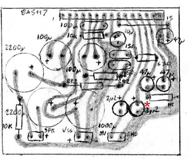
I left a space for a capacitor between IN2 and ground because I thought it may be needed, but it turns out that it isn't and the amp works fine with this input pin directly grounded. Therefore do not install this capacitor and short the two terminals (shown with the red asterisk). The BA5417 chip must be doing something internally to remove the half Vcc DC offset from the input pin.
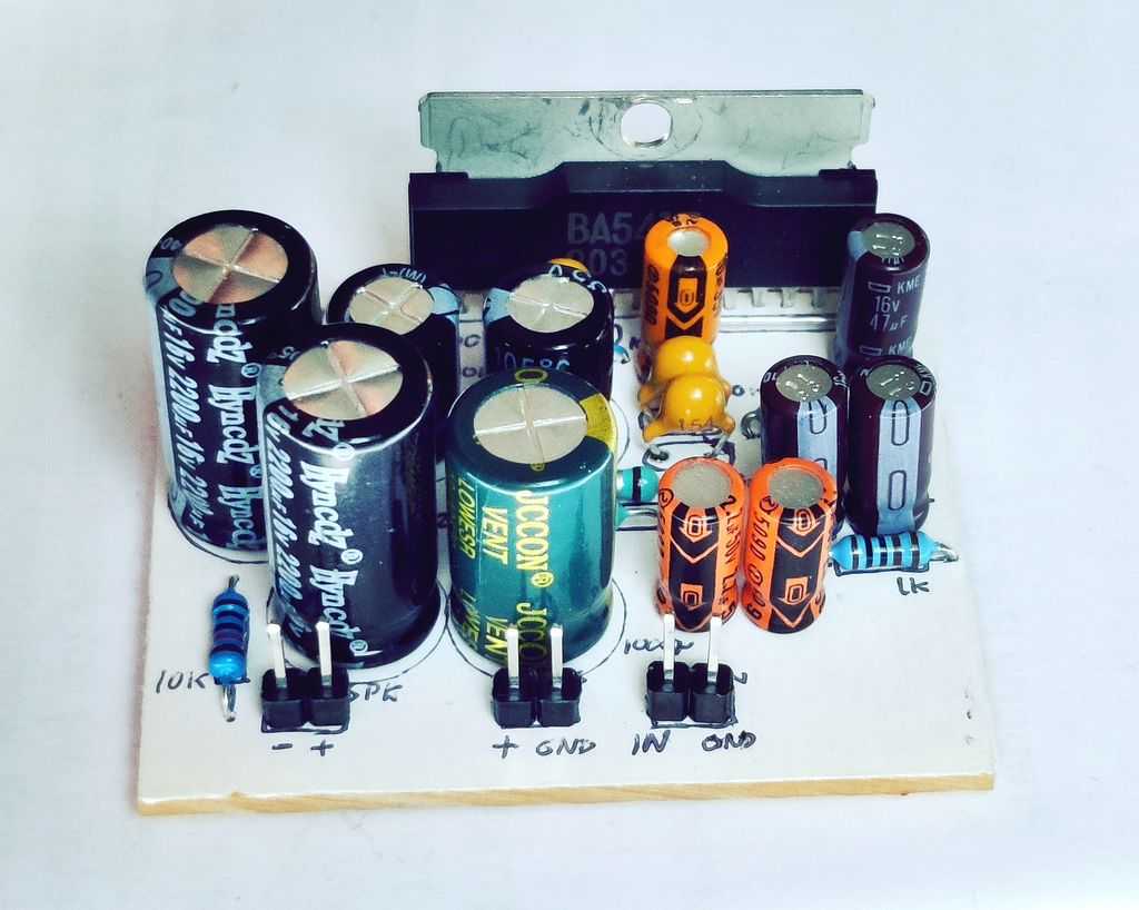
I've built this BTL version on a PCB and it works well. Little hum, good sound and reasonable heat output.
Components
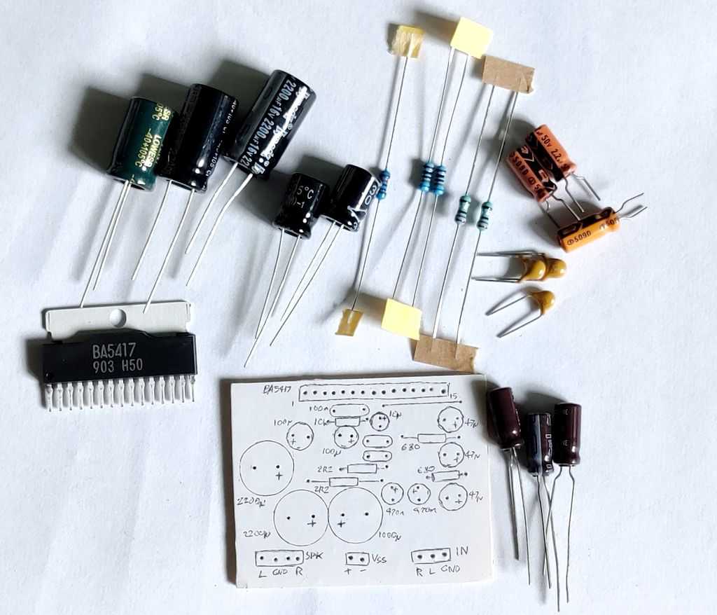
Above: You'll need to obtain quite a few components
Single ended components
| # | Type | Quantity |
|---|---|---|
| U1 | BA5417 | 1 |
| R1,R2 | 2.2 ohm Resistor, ½W Carbon, 5% | 2 |
| R3 | 10k ohm Resistor, ¼W Metal Film, 1% | 1 |
| RF1,RF2 | 680 ohm Resistor, ¼W Metal Film, 1% | 2 |
| Cin1,Cin2 | 2.2µF Capacitor, Polyester Film/Box (Best) or 16V+ Electrolytic (1µF is also fine) | 2 |
| C1,C7 | 150nF Capacitor, 50V+ Polyester Film/Foil/Orange Drop (Best) or Ceramic X7R | 2 |
| C2,C5 | 100µF Capacitor, 25V+ Electrolytic | 1 |
| C3,C6 | 2200µF Capacitor, 25V+ Electrolytic (16V OK if your supply is 12V) | 2 |
| C4 | 1000µF Capacitor, 25V+ Electrolytic | 1 |
| CB4 | 100nF Capacitor, 50V+ Ceramic X7R or MLCC | 1 |
| C8,C9,C11 | 47µF Capacitor, 25V+ Electrolytic | 3 |
| C10 | 10µF Capacitor, 25V+ Electrolytic | 1 |
| In L,R | 2.54mm header 3-pin | 1 |
| Vcc | 2.54mm header 2-pin | 1 |
| Spk R,Spk L | 2.54mm header 4-pin | 1 |
| Heatsink, cable, connectors | ~ |
BTL components
| # | Type | Quantity |
|---|---|---|
| U1 | BA5417 | 1 |
| R1,R2 | 2.2 ohm Resistor, ½W Carbon, 5% | 2 |
| R3,R4,R5 | 10k ohm Resistor, ¼W Metal Film, 1% | 3 |
| RF1 | 680 ohm Resistor, ¼W Metal Film, 1% | 1 |
| Cin1 | 2.2µF Capacitor, Polyester Film/Box (Best) or 16V+ Electrolytic (1µF is also fine) | 1 |
| C1,C7 | 150nF Capacitor, 50V+ Polyester Film/Foil/Orange Drop (Best) or Ceramic X7R | 2 |
| C2,C5 | 100µF Capacitor, 25V+ Electrolytic | 1 |
| C3,C6 | 2200µF Capacitor, 25V+ Electrolytic (16V OK if your supply is 12V) | 2 |
| C4 | 1000µF Capacitor, 25V+ Electrolytic | 1 |
| CB4 | 100nF Capacitor, 50V+ Ceramic X7R or MLCC | 1 |
| C8,C9,C11 | 47µF Capacitor, 25V+ Electrolytic | 3 |
| C10 | 10µF Capacitor, 25V+ Electrolytic | 1 |
| In, Vcc, Spk | 2.54mm header 2-pin | 3 |
| Heatsink, cable, connectors | ~ |
19 additional components are needed for both the OTL and BTL applications. That's 3 ceramic or MLCC capacitors, 5 resistors (6 for BTL), 11 (10 for BTL) electrolytic capacitors.
Like all amplifiers, the BA5417 needs bypass capacitors. C4 and CB4 are a 1000uF or better electrolytic capacitor, and a 100nF ceramic or multi-layer ceramic (MLCC) capacitor. Make sure the electrolytic is orientated correctly with + in the positive power supply. Both C4 and C4a need to be as close to the amplifier pins as possible, with CB4 (the 100nF ceramic) being the closest. CB4 is my own addition to the application in the datasheet to improve stability.
C4 needs to have a voltage rating of a few volts or more greater than the power supply you want to use. A 16V capacitor is just about fine for a 15V PSU if it's regulated. I've suggested 1,000uF for C4, but if you have a good power supply with capacitance exceeding this already, then C4 can be dropped to 470uF or 220uF.
As the BA5417 is a single supply amplifier, it generates a virtual ground internally that is half the supply voltage. This allows the audio input signal to swing above and below this virtual ground.
The input capacitors CIN protect that DC voltage offset from reaching your input source. These have no suggested value in the datasheet, but giving the input impedance of the amplifier is 30k, 0.22uF (220nF) input capacitors will give a cut off of 24Hz, but you can raise these to 330nF or higher to get the best bass response. Polyester is preferred for best audio quality, but an electrolytic works fine too and unless you're using this amp for the absolute best speakers in a quiet environment, you'll unlikely to notice the difference. The + pin of the electrolytic must be facing the amplifier pins.
DC blocking is also required on the speaker outputs - C3 and C6. These need to be quite large at 1000uF for 8 ohm speakers or 2200uF for 4 ohms, or the bass will be cut. These capacitors must have a voltage rating exceeding the power supply (so 16V capacitors will do nicely).
For resistors, there are two 1.5k ohm resistors, and two 2.2 ohm resistors needed. These should be 1% metal film, ½W minimum, but 0.6W metal film is obtainable and suggested.
The 150nF capacitors which make the Zobel networks (C1 and C7) may be ceramic or MLCC capacitors. The 100uF bootstrap capacitors C2 and C5 should be electrolytic and rated 16V or better. The DC blocking capacitors on the feedback attenuator resistors (C9 and C11) should be 47uF electrolytic capacitors with the + terminal facing the amplifier. 10V or better is fine for these. The filter capacitor C8 is also the same.
Do not run this amp without a heatsink, it will get extremely hot very quickly and shut down. The heatsink internally connects to ground which shouldn't cause a problem for most applications, however if your using the amplifier on mains power and your case is earthed (it must be for safety), you may need a loop breaker to avoid hum caused by other equipment that is also earthed, and in this case the BA5417 would need to be isolated from its heatsink in order to avoid shorting the earthed case to the amplifier power and signal grounds.
When mounting the amplifier chip to the heatsink, also use a line of thermal paste, and let the pressure of screwing it onto the heatsink push out the paste to cover the entire back of the tab. It's important to use thermal paste to improve the heat transfer, but do not use too much.
The gain of my BA5417 circuit is configured at about 26.2dB, which is a voltage gain of 20.4. That's calculated with the normal non-inverting amplifier gain calculation of 1 + (R1 / Rf). The feedback resistor (Rf) is internal to the IC, but the datasheet shows us it is 30k (RNF1 / RNF2). R1 is made up of the internal 45 ohm resistor, plus the value chosen for RF1 / RF2.
120 ohms is used as an example for RF1 / RF2, so that gives 1 + (30000 / (45+120)), giving 182.8. In dB that would be 20*log(182.8) which is 45.2dB. That's extremely large, so with my suggestion of 680 ohms for RF1 / RF2 - this gives 1 + (30000 / (45+680)) = 42.4, which is a 'normal' gain of 32.5dB. If that's not enough (or still too much), you can put higher or lower values for RF1 / RF2 into these formulas to get the gain you need. For example, using 1k5 ohms for RF1 / RF2 gives a gain of 20.4 (26.2dB),
Consider how much gain you need. If you have the crazy gain of 183 (per datasheet), with 15V input power, the BA5417 can drive a 4 ohm speaker to about 6W RMS at 10% distortion. The output voltage of is V = √(6 * 4) = 4.9V RMS (actually it's a little more because distortion is 10%). Divide (say) 5V by 183 and it's just a 27mV RMS input signal required to drive the BA5417 to an unacceptable distortion. With the gain as 20.4 though, a 240mW signal is enough to go into distortion. A signal of 240mW is easily obtainable from smartphones, mp3 players, Bluetooth receivers etc., and you'll still need a volume control to attenuate the signal.
Finally, R3 and C10 make a small time delay circuit so that the amplifier stays in standby for a brief moment after the power is applied. This helps prevent power on pops.
Optionally, you can leave R3 and C10 out of the circuit and connect pin 8 directly to Vcc, but you'll get a power on pop. You could also connect pin 8 to the output of a microprocessor too, as any voltage above 3.5V will allow a microprocessor to put the BA5417 in or out of standby. Use a 5V microprocessor if you can, as a 3.3V one (including Raspberry Pi) may not give enough voltage to make the BA5417 power on.
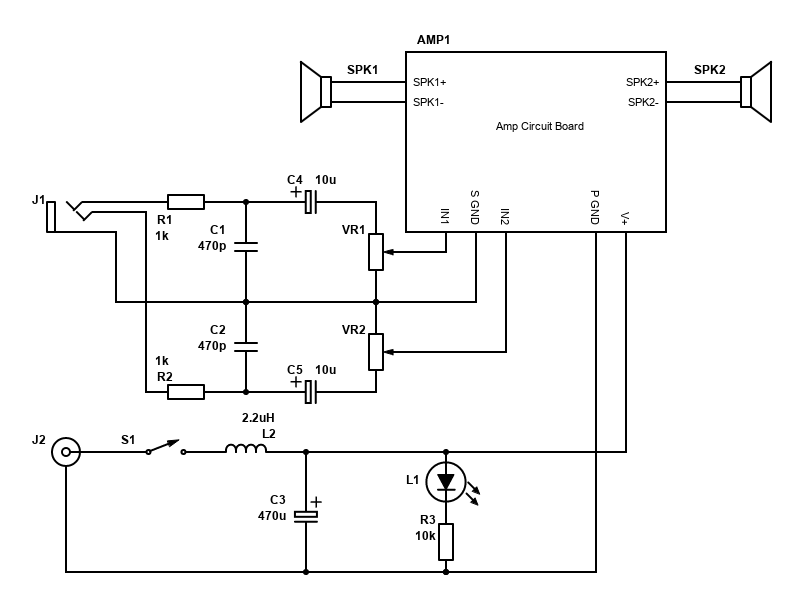
Making a 'system'
If you want to build your own stereo amplifier system, you'll need a little more than the circuit and components above.
- A power supply - see below, but suggest an external power supply
- A DC jack such as a standard 2.1mm jack. It should match the plug on the power supply
- A power switch, such as a slide switch, toggle switch or latching push button
- A power LED and current limiting resistor (you may have an LED in your power button you can use)
- 3.5mm jack input or phono sockets for connecting your source
- A dual gang potentiometer, 10k log is recommended
- Optional, but recommended, capacitors to block radio interference
- Optional, but recommended, a capacitor and inductor to improve PSU noise
- Optional, but recommended, capacitors in front of potentiometer to block DC
- If your speakers are separate from the amplifier, spring clips, female banana plug sockets or similar should be used to attach/detach the speakers
With the gain configured to the suggested 26dB, it's unlikely you'll need a preamplifier and you'll be able to use most sources directly. This could be your TV, smartphone, a Bluetooth audio module, Chromecast audio (if you can find it to buy) or many other devices.
When connecting all connections, tightly twist the related wires together. This is applicable to all related connections where there is a signal and a return, so twist the L/R input with the signal ground together, twist each speaker +/- wires together, and twist the voltage + supply and power ground together.
Twisting related flow/return wires together likes this both prevents them radiating interference, and also protects them from interference. Each twisted set in a system should be kept away from each other and if they must be close, let them cross at right angles and don't run them parallel to each other. This is to reduce hum.
The PCB layouts above have the signal and power grounds joined together at the board, therefore do not have these connecting anywhere else to avoid hum caused by ground loops. If you do have a wider system and have these power and signal grounds joined at another point, consider removing the join at the board and replacing it with a 10 ohm resistor, in parallel with a 100nF capacitor.
The potentiometer should be a dual gang one, so both channels are adjusted together. 10k Log type is ideal. It will have three pins per channel. The first pin will be the one connected to signal ground, the middle pin to the audio input and the final pin as the audio output. This will ensure that turning the volume control clockwise raises the volume, anti-clockwise lowers it.
Before the volume control are a 10uF capacitors on each signal (C4 and C5). These block any DC offset the source may or may not have. DC voltages cause the potentiometer to become noisy over time (particularly when adjusted), so the capacitors improve its life. We don't have to worry about any capacitor after the volume control because the capacitor is the first component in series with the input signal at the amplifier itself.
At the input socket are two RC low pass filter (one for each signal). The component values are not too critical here, it's just to ensure signals of MHz's are removed so with the combination of 1k ohms and 470pF (picofarads), frequencies above 340kHz are removed. This will remove any GSM pulsed buzz / interference from mobile phones, as well as any AM radio stations creeping in.
At the power supply, the switch is first, on the positive line. I suggest to get a latching push button switch with an LED built in for convenience, but check whether the LED needs a resistor or not (some are 12V ready). Otherwise having a separate LED to indicate whether the power is on is useful. The value R3 should be adjusted to suit your power supply and LED type (search for LED resistor calculator).
Then there is a filter formed by a 2.2uH power inductor (capable of handling 6A current) and a 470uF capacitor (this must be a low ESR type). These are there to reduce the ringing/whining noise from noisy SMPS power supplies. Anything above 5kHz on the PSU is cut. You may not need the inductor if your power supply is quiet, but I still suggest the capacitor for smoothing the voltage.
Power Supply
I recommend, especially for beginners, that an external power supply is used. This should be a linear power supply or switching power supply that is suitable for audio/video use (i.e. a 12V or 15V laptop power supply). These types of power supplies are easy to obtain.
Be wary of cheap power supplies ordered from the far east and elsewhere because although they may work fine, they won't be safe in overload or other situations (lightning strikes etc.). The CE symbol on these devices is either fake or means 'China Export' and isn't the European certification that guarantees the product conforms with health, safety, and environmental protection standards.
With a 15V supply, this amplifier can give 3.5W into 8 ohms at a 10% distortion, but it will only be about 2W at 1% or lower distortion. For some applications this will be enough. The power supply will need to be 12W minimum (that's 0.8A output for 15V) though 18W (1.2A) or higher is more comfortable.
If bridged into 8 ohms, output power is much greater, possibly up to 12W. For a single amp therefore a 22.5W I'd suggest as a minimum. That's 1.5A for 15V. If you've got two BA5417 chips in order to get a bridged stereo output, then double that again (45W = 3A @ 15V).
If you decide to build your own power supply, you can use a 9V AC 50VA transformer to get about 12V DC when rectified. See the TDA2003 article for a suitable schematic, but bear in mind you will be working with mains electricity. MAINS ELECTRICITY IS DANGEROUS - make sure you are qualified, understand your liability and ensure that your build is properly earthed. The unregulated output from this should be fine, but if you want the best noise performance, using regulator capable of 2A or more (LM338T for example) with large heatsinks and a 12V AC transformer.
Performance
When wired correctly, the BA5417 is a pretty good amplifier. It sounds absolutely fine and is perfect for driving small speakers and even larger speakers to some extent. Because of the limited power output, speakers with high sensitivity are best if you need high volume, but on most speakers it's capable for indoor use. I ran my OTL BA5417 PCB on a couple of small 4 ohm speakers and a 12V PSU... there was plenty of volume available, and it sounded good!
This amplifier is also applicable for your low power battery operated devices too. You can't go lower than 6V with the BA5417, so 4x AA batteries wouldn't work well, but 5x or more would and I'll leave it to you to weigh up the benefits of either more batteries for more power, or less for less weight.
One feature the BA5417 does have is soft clipping. Clipping is still clipping (therefore bad), but soft clip will sound less harsh compared to other amplifiers when clipping.
As mentioned though, there's little benefit of this amplifier over alternatives such as the TDA7266, TDA7297 or STA540/TDA7375 chips. These are all better performing, have less distortion, and are less complicated. All of these alternative amplifiers give you a bridged stereo system on a board smaller than the BA5417, plus the chips are easier to mount both to the board and to a heatsink. The only advantage the BA5417 does have is the gain can be configured to whatever you want if you really need a specific gain configuration.
If you've brought from a cheap supply of this chip in your country though, or you've salvaged it from an old ghetto-blaster, midi system, TV or whatever, definitely keep it as it still makes a good low power amplifier!
BA5406 application
Quick facts BA5406
- Power output: 5W + 5W into 3 ohms at 10% 1kHz distortion with power supply 12V
- Power output: 6.8W + 6.8W into 4 ohms at 10% 1kHz distortion with power supply 15V
- Power output: 3.8W + 3.8W into 8 ohms at 10% 1kHz distortion with power supply 15V
- Power output: 2.5W + 2.5W into 8 ohms at 10% 1kHz distortion with power supply 12V
- Power output: 13W + 13W into 8 ohms bridged at 10% 1kHz distortion with power supply 15V
- Gain: 46dB per datasheet, 31.2dB for my suggestion, variable
- Power supply: 5V to 15V single supply
- Class AB
- Datasheet available here
The BA5406 is a similar chip as the BA5417, but it's larger, although it has less pins. It's power output according to the graphs looks slightly better, but that's at 10% distortion so the difference would be pretty much unnoticeable in real life. In typical operation, the total harmonic distortion of the BA5406 is worse at 0.3% vs 0.1% of the BA5417. That's enough to not consider it for 'real' hi-fi, but still good enough for lots of applications.
The BA5406 can also operate with a power supply down to 5V vs 6V of the BA5417, but you'll get less than 0.5W per channel at reasonable distortion though.
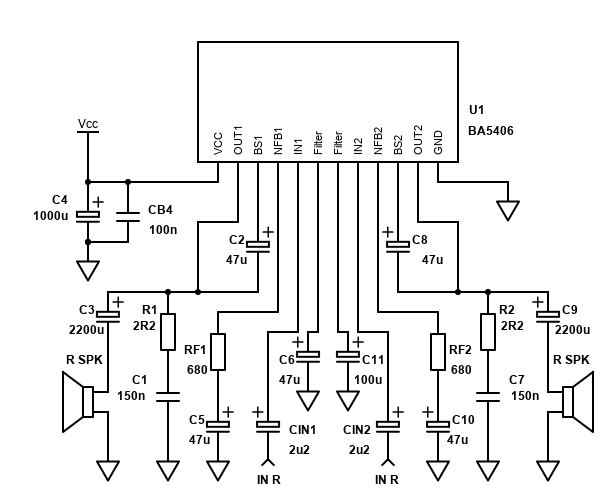
Most of the above guide for the BA5417 is appropriate, however the schematic is different and because the chip is physically a different size, the PCB for the BA5417 cannot be used.
Because it's rarer, it seems to be a little more expensive than the BA5417, but not overly so. It may be more desirable because it will mount on to a heatsink with less thermal resistance and it has standard 2.54mm spaced pins in SIL configuration which allows building on stripboard with minimal cutting needed. I found it easier to work with myself and slightly prefer it.
| # | Type | Quantity |
|---|---|---|
| U1 | BA5406 | 1 |
| R1,R2 | 2.2 ohm Resistor, ½W Carbon, 5% | 2 |
| RF1,RF2 | 680 ohm Resistor, ¼W Metal Film, 1% | 2 |
| Cin1,Cin2 | 2.2µF Capacitor, Polyester Film/Box (Best) or 16V+ Electrolytic (1µF is also fine) | 2 |
| C1,C7 | 150nF Capacitor, 50V+ Polyester Film/Foil/Orange Drop (Best) or Ceramic X7R | 2 |
| C2,C5,C6,C8,C10 | 47µF Capacitor, 25V+ Electrolytic | 5 |
| C3,C9 | 2200µF Capacitor, 25V+ Electrolytic (16V OK if your supply is 12V) | 2 |
| C4 | 1000µF Capacitor, 25V+ Electrolytic | 1 |
| CB4 | 100nF Capacitor, 50V+ Ceramic X7R or MLCC | 1 |
| C11 | 100µF Capacitor, 25V+ Electrolytic | 1 |
| In L,R | 2.54mm header 3-pin | 1 |
| Vcc | 2.54mm header 2-pin | 1 |
| Spk R,Spk L | 2.54mm header 4-pin | 1 |
| Heatsink, cable, connectors | ~ |
Once again, ROHM application schematic shows a remarkably high gain as the default configuration. This time it is 200x (46dB) - calculated as 1+(24000÷120).
I suspect that will be too high for most applications and you should aim for about 20x to 40x (26dB to 32dB). Using a 680 ohm resistors instead of 120 ohms gives a gain of 36x (31.2dB).
The pin layout on the BA5406 is a bit easier to work with than the BA5417. In fact, most of the pins are just a mirror of each other and the BA5406 is easy to treat as two independent amplifiers on one chip that only share the same power supply and ground.
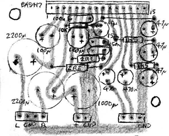
Below is an example of how a stereo amplifier could be laid out on stripboard. I've not built this stereo version, but there's no reason why it would not work.
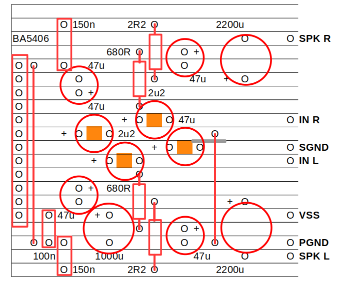
Note that there are several breaks in the strips to be made on the board - shown by the dark orange blocks. Cut these with a stripboard cutting tool, or use a drill bit briefly or cut carefully with a modelling knife. There is also a little bridging between adjacent tracks - shown by the grey lines. Do this bridging with solder after soldering the components in place, but do it carefully so you do not overheat components nearby.
The BA5406 does not have any standby capability. It does have the capability to mute itself, which you would do by pulling the filter pins to ground, but this would require some further components (i.e. transistors) to interface safely to a microprocessor.
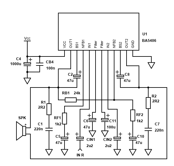
ROHM did not show any application or do any tests on the BA5406 in BTL mode, but as two independent single ended amplifiers, there is no reason why they cannot work in BTL mode and I've shown a circuit that works fine.
| # | Type | Quantity |
|---|---|---|
| U1 | BA5406 | 1 |
| R1,R2 | 2.2 ohm Resistor, ½W Carbon, 5% | 2 |
| RF1,RF2 | 1.2k ohm Resistor, ¼W Metal Film, 1% | 2 |
| RB1 | 24k ohm Resistor, ¼W Metal Film, 1% | 1 |
| Cin1,Cin2 | 2.2µF Capacitor, Polyester Film/Box (Best) or 16V+ Electrolytic (1µF is also fine) | 2 |
| C1,C7 | 150nF Capacitor, 50V+ Polyester Film/Foil/Orange Drop (Best) or Ceramic X7R | 2 |
| C2,C5,C6,C8,C10 | 47µF Capacitor, 25V+ Electrolytic | 5 |
| C4 | 1000µF Capacitor, 25V+ Electrolytic | 1 |
| CB4 | 100nF Capacitor, 50V+ Ceramic X7R or MLCC | 1 |
| C11 | 100µF Capacitor, 25V+ Electrolytic | 1 |
| In, Vcc, Spk | 2.54mm header 2-pin | 3 |
| Heatsink, cable, connectors | ~ |
Like the BA5417, BTL will offer 4x more power output into the same speaker impedance, but the 3 ohm speaker impedance limit will now be 6 ohms, so do not use the BA5406 in BTL mode into 4 ohm or lower speakers.
As the power output is 4x higher (6dB) into the speaker, the gain in my BTL circuit has been reduced to 21 (26.4dB) by using 1.2k resistors, though I used 1.5k in my own build (gain of 17).
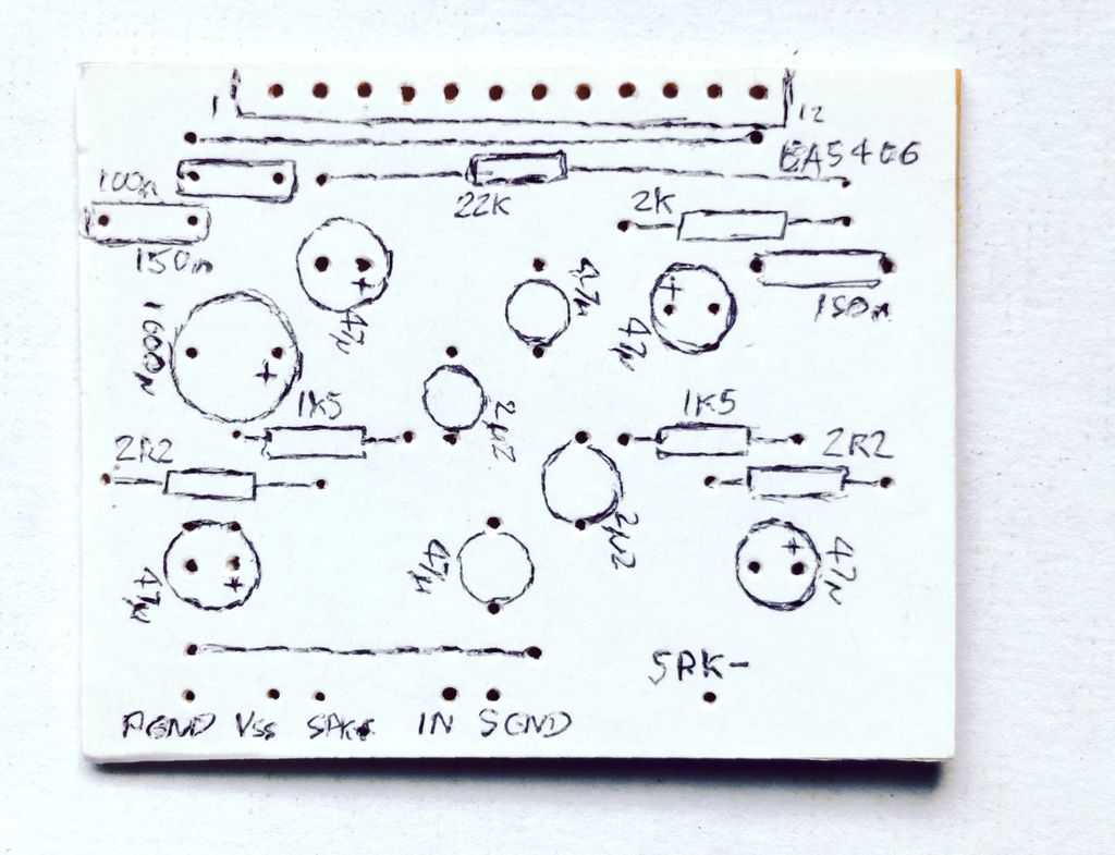
Below is a copy of the layout I used to build this BTL amplifier on stripboard. It works effectively and being BTL it gives a decent amount of power output from a 12V PSU, and will give even more if you've got a 15V PSU.
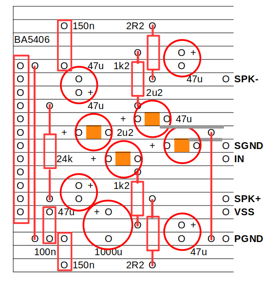
Note again there are several breaks in the strips to be made on the board - shown by the dark orange blocks. Again there is bridging between adjacent tracks - shown by the grey lines. Bridge these with solder.
The BA5406 is bridged by using a 24k resistor between the output of the first amplifier, and the inverting input of the second. It's critical that this is 24k in order to match the internal feedback resistor. On my build, since I did not have a 24k resistor, I actually used 22k and 2k resistors in series (summing to 24k of course).
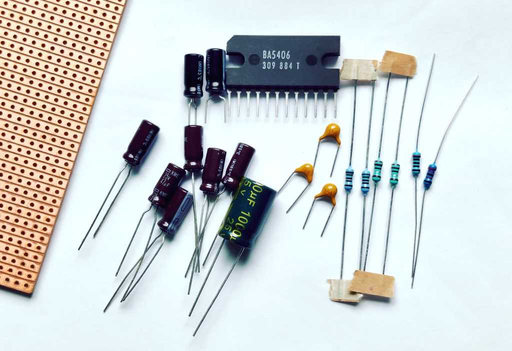
Above: Quite a number of parts are needed
Most of the components needed for the BA5406 are the same as the BA5417, but it's one less than the BA5417 (18 for stereo, 17 for BTL). That's 3 ceramic or MLCC capacitors (the 100nF and 150nF capacitors), 4 resistors (5 for BTL) and 11 electrolytic capacitors (9 for BTL).
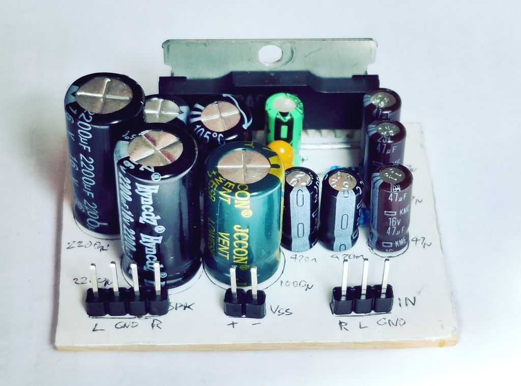
Above: Above layer of the stripboard prior to soldering
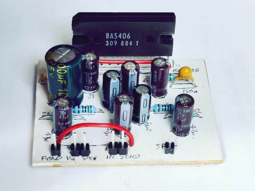
Above: Completed stripboard view
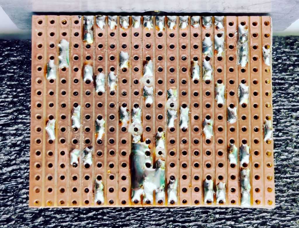
Above: Bottom view of the stripboard showing the soldered strips
Like all Class AB amplifier chips that output more than 0.5W, a heatsink is needed. The BA5406 has two mounting holes at the side for heatsink mounting so you may need to drill them yourself. The mounting holes are 24mm apart, and you'll want them about 12mm from the top of your PCB (depending on how far through the PCB you solder the chip). Because there are two holes, it is much easier to mount properly to a heatsink. Without a heatsink, the chip will become damaged because it does not have thermal protection - so mount a good heatsink on it, even for a quick test!
As the BA5406 does not have thermal shutdown or short circuit protection, if you get it wrong, it's not as forgiving as other amplifiers . I suggest to double check your PCB or stripboard layout and especially to check that no tracks are shorted. Once it's working, there's no reason why it won't last years though and if you're building one, even nowadays, the result is still pretty good.
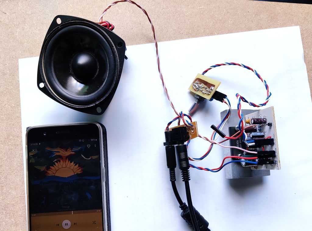
Above: First test of the BA5406
Despite its age, and the amount of parts, it still sounds like a pretty good amplifier and if you've obtained one through a salvage or a cheap supplier I do recommend building an amplifier out of it and putting it to use!
References:
BA5417 / BA5406 datasheet
BA5406 (specific) datasheet
Quasar Electronics AS3090HKT - 3W Stereo Amplifier
Kit
ESP - Simplest Ever Bridging Adapter for Power Amps