
Gigabyte B450 I AORUS VRM Heatsink Modification
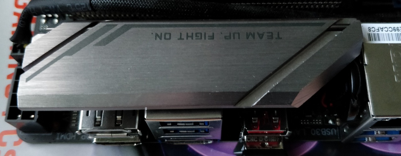
The heatsink on the Gigabyte B450 I AORUS
The Gigabyte B450 I AORUS Mini ITX motherboard was an excellent value way to get an AMD Ryzen 5 3600 PC into my mini ITX build. Whilst my first choice at the time was out of stock, this board does have some nice features that kind of justify its price.
One concern I had however was around the VRM temperatures. My worry was that this was the cause of my PC to shut down due to heat issues, which I solved by improving the cooling - see Kolink Rocket Case Cooling Airflow Mods.
Note: Doing modifications like this voids the warranty
However, I was inspecting the design and had concerns around the thickness of the Silicone pad (Sil-Pad) between the VRM chips and the heatsink itself.
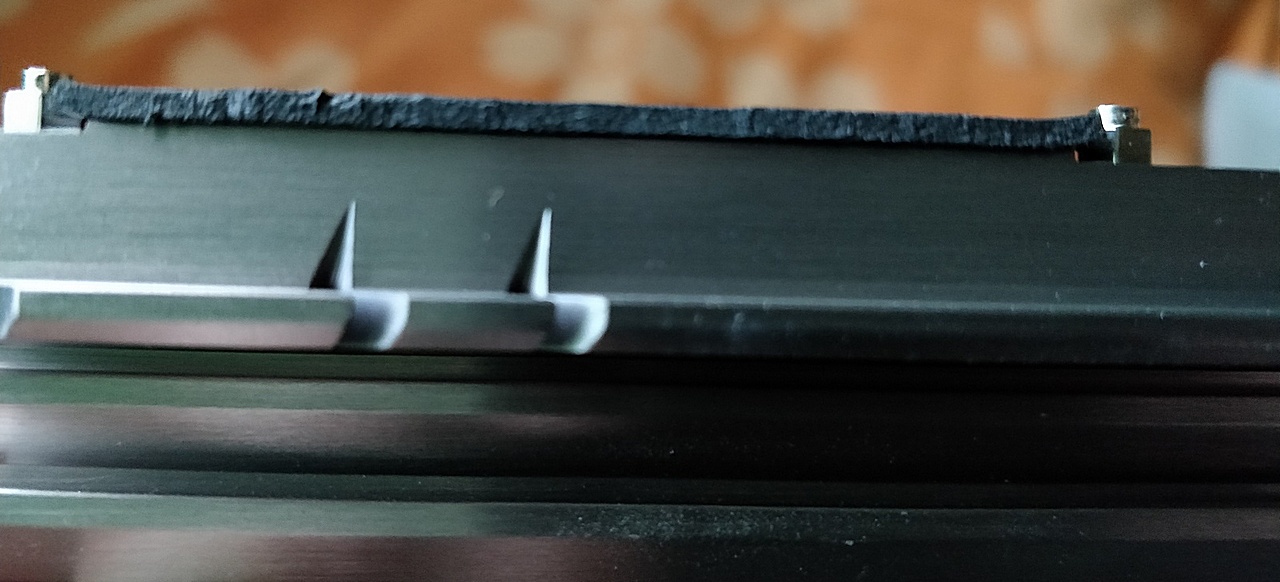
Very thick Sil-Pad
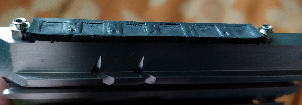
Showing the indentation of the chips
Whilst the VRM temperatures after my cooling modification were not exceeding 60 degrees (according to the temperature sensor) - at this temperature I'd expect the heatsink to feel pretty hot to touch, which it wasn't. With the 'touch test', the heatsink was certainly pretty warm, but I could leave my finger on there.
The heatsink isn't perfect - it has no fins, but it could be put to better use, so I had a thought about how to reduce the thermal resistance between the chips and the heatsink.
By removing the stands from the heatsink, it can sit closer to the board, touching the VRM chips directly. The two screw holes left are fine for screwing the heatsink to the board directly with a couple of screws I saved from an old laptop or PC. I think it was M3 size.
The heatsink is metal though, and I did not want it to short with the legs of the VRM or surface mount capacitors/resistors also in the same area.
To electrically isolate the heatsink - I used Kapton tape. I purchased some from ESP along with some circuit boards some time ago, and whilst thermally it isn't the best performer, the tape is only 25 μm thick. That's thinner than human hair, and means it is thermally performing well.
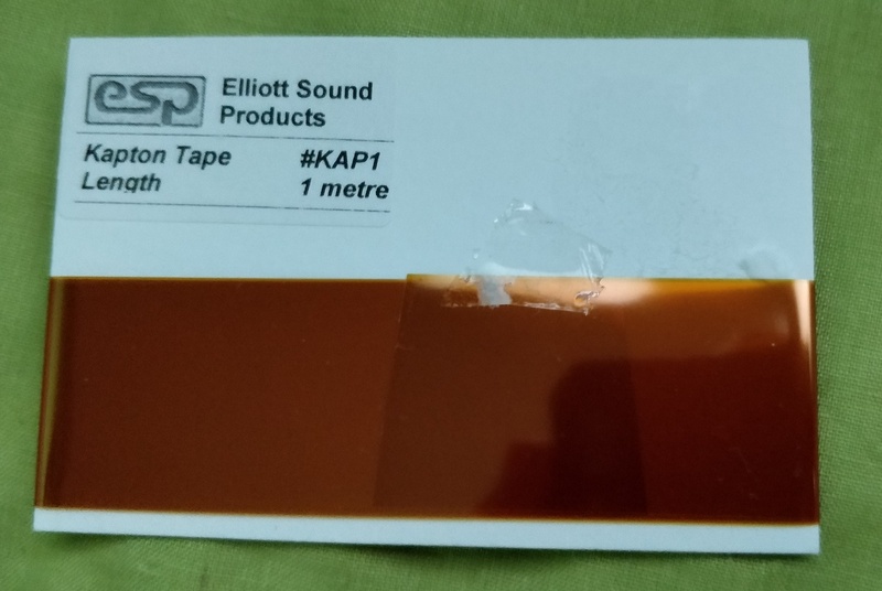
Kapton tape
I used non-Silicone, non-conductive heatsink compound on both side of the tape, ensured it was central on the heatsink and remounted it to the board.
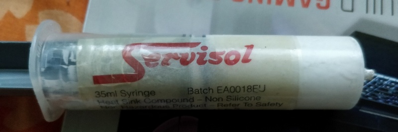
Heatsink compound
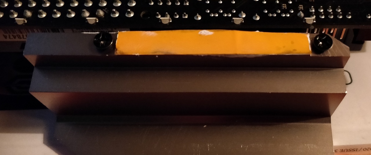
Tape mounted on the board, first layer of compound underneath
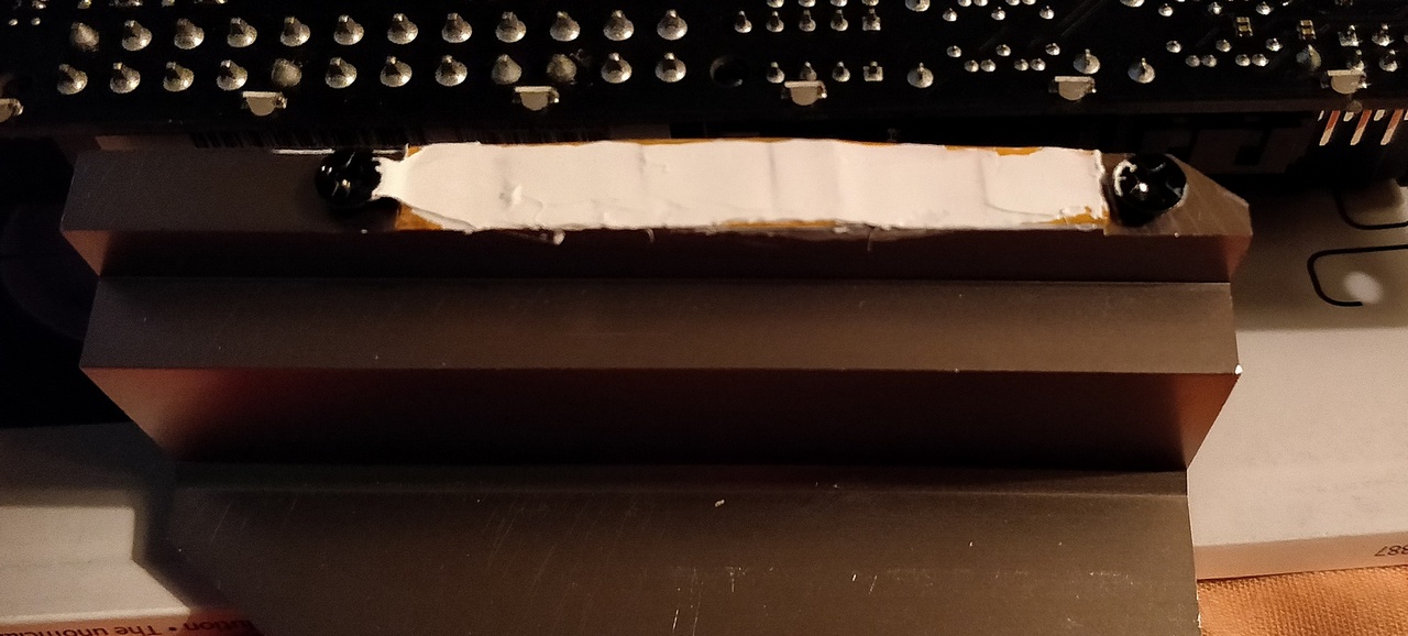
Second layer of compound - fairly thick, but the small VRM chips will push it out
It mounts much closer to the board now and has improved the VRM temperatures under load. Sadly, I lost my original readouts prior to the mod, but now they are now no higher than 56 °C when the CPU is under a 12-thread stress test.
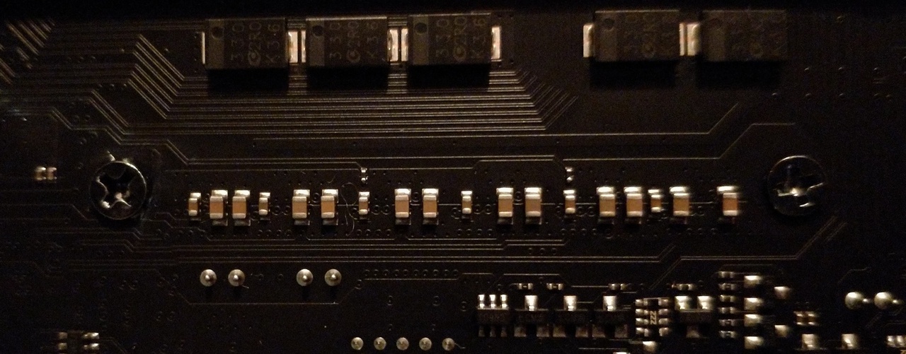
Underside of the board using the new screws directly into the heatsink