
12V PC fan 4 pin PWM header to 3 pin fan
The quick and simple PWM to standard 3 pin fan controller
I have a couple of old Intel H61 based (released 2012) Mini ITX systems where the motherboard has 4 pin system fan header, but the case contains only 3 pin fans, and thin varieties that are hard to get in a 4 pin version.
Connecting the 3 pin fan to the 4 pin fan header makes it run full speed, all the time. This is noisy!
Only premium or more recent motherboards have the ability to speed control 3 pin fans, and it's a nice ability because when the PC is mostly idle, having the system fan reduce to a nice quiet speed is welcome, but it has the ability to pick up speed when you stress the CPU or other hardware causing the internal temperate of the system case to rise.
This isn't my own design, it's lifted straight from a TechPowerUp forum post and a similar version is on a post on Electrical Engineering Stack Exchange. My addition to it is a couple of easy board layouts you can consider, and a confirmation that it works well.
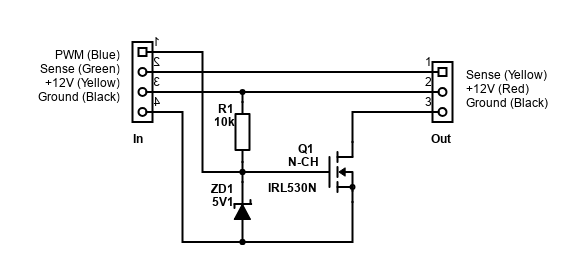
Note fan wire colours are a guide only and may not match
Having plenty of 10k resistors and 5.1V Zener diodes, I decided to order some IRL530N N-channel MOSFETs. This is a logic level MOSFET, other alternatives are available (like NTE2985, IRLz24 and FQP30N06L mentioned).
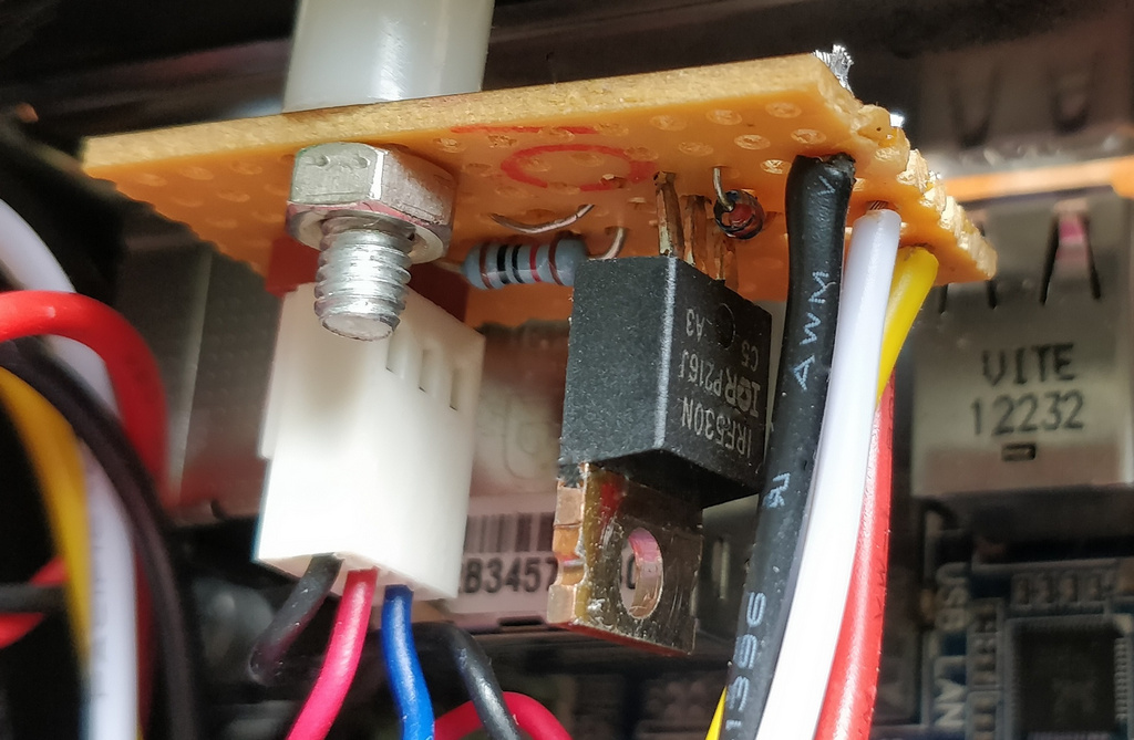
It was quick and simple to build on stripboard/Veroboard and works perfectly, taking less than an hour to build and total cost less than £3 (most being postage), with cost rapidly falling depending on how many you build.
The challenge can be getting the fan headers in the first place - because you need a 4 pin male header, and a 3 pin female header. Dupont connectors do have the same pitch (2.54mm) but it's easy to put them in reverse. If you can't find the connectors, buy a 4 pin to 3 pin adaptor, and chop it in half so the circuit can be placed in between. Alternatively, a 4 pin fan extension cable (the 3 pin plug still fits in the 4 pin socket). In my example, I even had a 3 pin socket I de-soldered from a dead motherboard.
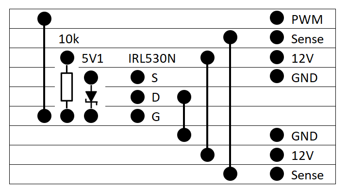
It's easy to build. I've provided two stripboard layouts here. One involves more jumper wires. For this one you can use the offcuts from the resistor and diode - those will give the 4 jumpers required.
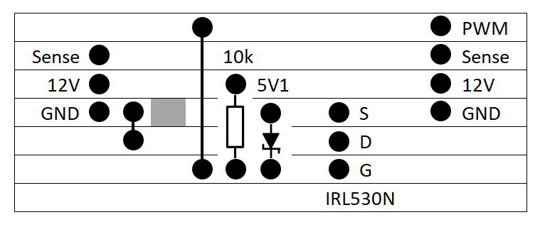
The other layout is more compact with less soldering but will require you to carefully cut on of the tracks (where the grey box is).
Pay attention to which way round the headers go, and the MOSFET itself. If designing your own, ensure that you leave space either side of the MOSFET and the headers since they are a bit wider than the 2.54mm spacing between each row/column provides.
If you drill a hole in the board to mount it - ensure that extra height is available for that. The hole cannot cross any tracks which you have soldered components to as when the screw passes through the hole, it will short the tracks, or short at least one of them to the PC case (ground).
No heatsink is required for the MOSFET unless you put many fans from it. The MOSFET can handle up to 15A, but chances are your PWM output from the motherboard can handle much less, so if you're intended to hook up more than 1A (about three fans), just build a few more of these circuits and use other headers if they are spare.