
My 5-channel power amplifier with bi-amplified main stereo.
I suggest reading about the rebuild first. Information below is for reference purposes.
Contents
Page 1 - Idea and circuit choices
Page 2 - P3A Amplifiers
Page 3 - Crossover and Surround Channel Amps
Page 4 - Power Supply details
Page 5 - Testing
Page 6 - Improvements
Testing and Configuration
With most of circuit boards now complete, I could now begin to wire them all up and start testing.
I wasn't to obtain a case however from some time as I was planning on constructing my own. What I did do is restrict myself to quite usual dimensions for hi-fi equipment. My initial layout was planned on graph paper, and I was quite pleased with the kind of result this gave.
The design is here. To maintain clarity I could not make it any smaller than a width of 1024, so if you have a smaller screen, you'll need to scroll. A preview is not on this page, and it is simply linked above as it is 180KB.
The final design changed a bit since this drawing was made as I included the soft start and pre-regulator at a later date, and also the centre channel amp was to be a lot bigger.
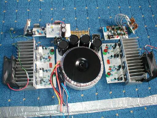
My initial layout of boards.
The above layout is slightly different to the hand drawn design, and this was still not going to be final.. but close.
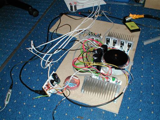
I got impatient from here onwards and decided to start soldering the boards up because I had a very good idea of what the final layout would become. To allow for testing and good design (i.e. wire length) I got an old piece of MDF and started making it up on that...
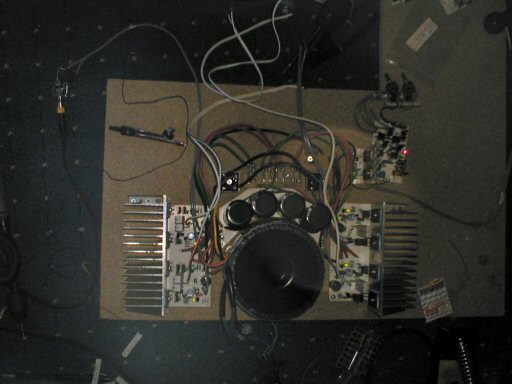
This image was done in low light so you can see the LED's glowing - it was my first test.
As you can see at this point there is no soft start circuitry or any rear or centre amplifiers. I didn't have the heatsink for the rear and centre amps at the time anyway. This was mainly to test the P3A
P3A Configuration and testing
I already worked with the power supply and tested that throughly to see if both rails measure what I wanted them to be. Both were about +/-38V... but this is the unloaded voltage as at that time there was nothing connected beyond the capacitors. This testing actually went ahead before I constructed the whole thing on a piece of MDF.
The MDF came into the equation when I wanted to hook up all my P3A's.. and that I did. I removed all the fuses from the fuse board so I could test each one of the 4 amps individually.
But before any fuses went in, it was time to install the temporary 22 ohm 7 watt resistors. It was a good job I did too. The first P3A I tested powered up, and I could smell something burning, whilst I was measuring the outputs. It was the 22 ohm resistors that were burning.. or rather one of them.
Piping hot it got, so I removed the power quickly. The resistor was still measuring the correct resistance so I hadn't managed to burn it out. However I was curious to see if the same would happen to the other three amps.
The next one didn't do anything unusual at all. Things were ok with that one, and everything measured out to be normal. The same with the third one I tested. But the forth done the same as the first and the same resistor got hot.
This time I managed to measure the rail voltage.. and it was something very different to what was normal. This, and the same fault as the first amp gave me a clue to it must being my PCB layout.. especially as the forth amp to fail was on the same side of the second P3A PCB as the first. It had to be layout.
The P3A's were unscrewed from the MDF and layout checking began. I found the problem, and from what I remember, one of the amplifiers on the PCB was only getting -35V to Q8, but not anything else!
A chopping from my large diodes I used in my loop breaker soldered across two tracks that were meant to be linked, and a re-test confirmed that every amp was now ok.
It was now time to test each amp with a load. I hooked up my test speaker and feed each amp a signal. I got a decent amount of sound out of my test speaker. All amps passed this test fine.
Next it was time to test without the safety resistor, and with the fuses. Again, everything measured out ok and I had the confidence that these amps were ready for use very soon as nothing got hot. The load and signal was reconnected and I got a fair bit of volume out of the amps, with no bias set correctly yet. I took time to smile and enjoy the fact I am now at this stage.
Setting the bias was a bit of a pain. I made two mistakes during this task. The first two amps I had no trouble with - and I set the bias correctly - as shown below.
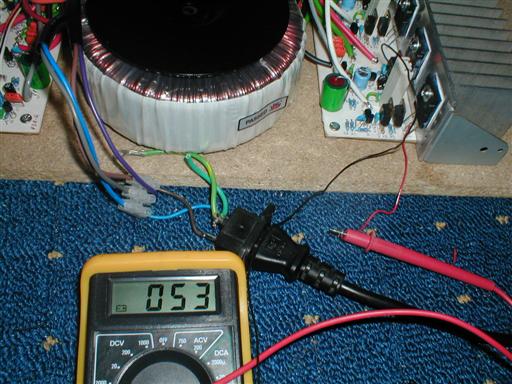
P3A bias setting - close enough to 50mV. You can also see how I had to wire my multimeter to keep both
hands free to turn the bias adjust pot.
The bias has to be set twice, as the amps will warm up after a couple of minutes and the reading will climb to over 60mV - a bit too high.
During setting the bias for the other two amps, I was getting negative readings on my multimeter, but I thought that would not matter as my DMM works both positively and negatively. I thought wrong and the last two amps got rather hot without doing any work.
On reversing the multimeter connections to as they were for the first two amps.. I find out I had readings of more like 500mV - or 0.5V (!). I went to correct that.
Sparks flew. I made the silly mistake of trying to adjust the setting when I wasn't ready to. My hand shook and I shorted two components on the board. A very hefty spark was produced, as I was shorting the positive supply rail with something else... and D1 went out.
I then set about replacing every active component (transistors and D1) except the power transistors, before I realised that the amp was dead because the fuses had blown (duh). And boy had they blown - bits of the fuse wire were scattered all over the glass.
A simple replacement of the fuses and the amplifier was working again, with the correct bias setting. But to add insult, I proceeded to accidently short the collectors of Q7 and Q8 via the heatsink, but the fuses went again and no component was harmed (phew).
Moral: Fuses are important!
And secondly: Connect the multimeter the right way round... positive to the collector of Q7, negative to the collector of Q8.
Speaker modding
An important part of bi-amping is removing the passive crossover inside the speakers (unfortunately).
Here is a quick description of how I modified my Modaunt Short MS20i Pearls to take bi- amplification.
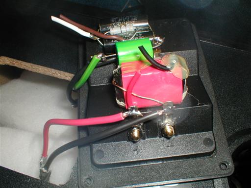
A time consuming task of soldering and chopping.
What took the most time is extending the existing wires. They were so short they only just reached the existing crossover. I needed to extend them so I could work properly and unsolder the existing network and solder in direct connections to the woofer and a 4.7uF capacitor in series with the tweeter.
What is the 4.7uF capacitor for? Two reasons. The first is important!
Despite the signal being crossed over before it reaches the amplifier, low frequency can still get through and destroy the tweeter. This happens for example if the power amplifier does a low frequency thump at turn off, or click on power on. The 4.7uF capacitor will remove these are avoid harm to the tweeter.
The second reason is so I can still hook up the missions normally and have acceptable tweeter usage for normal single amplification, though I am aware I would not use much power in this case.
Crossover testing
The crossover didn't work perfectly first time. There was some awful distortion on one channel, but I solved it simply by replacing the NE5532 op-amps. Apart from the output buffers, I now have MC33078BP in the crossover and quality is good.
The second problems was the heat produced by the onboard 7815/7915 regulators. Everything was clearly working correctly, but they needed heatsinks. I'm still not sure why they warm up so much for powering 9 op-amps.
Finally, as I described earlier, my pre-regulator was also heating far too much. Changing the resistor values in this solved that.
Once I had the crossover working properly, and all 4 P3A's hooked up, I could enjoy. It was nice getting so far.
Soft start circuit testing, and final layout
I took a lot of care designing and building the soft start circuit. As a result I had no problems whatsoever. It worked first time, and I was proud of the results. See the last page for further descriptions.
Final layout, all working with the soft start circuit.