
More TDA7052 Amplifier Developments - 2
Small Stereo Portable amplifier
This system is just a small stereo amplifier only that I built in 2004. I can't find the original full size pictures, so the ones below are small as this was written when a lot of the UK was still on dial-ip internet.
It uses two TDA7052 chips, notes are available on this chip here. The small DC socket can accept most DC adaptors or a battery back (which I have built many of, e.g. for the above project). The line input is in the form of a stereo 3.5mm jack socket (which is the most useful) and it has two phono sockets for the amplified output to each speaker.
The primary need for it is something simple just to power my rear speakers for a small surround sound application in my own room. It can also serve as a good audio system to plug my laptop into when I am laying in bed. It needs some power, but also needs to be small and portable (well I wanted it to be anyway). Of course, making it look good too would be an added bonus.
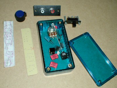
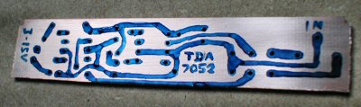
The box itself is a very small box, which is a nice translucent blue. It is 100mm long, 50mm wide and 25mm deep at its external extremes. The PCB is just 18.5mm x 95mm and houses two TDA7052 amps, a dual volume control, a stereo jack input socket, and LED and a 2.1mm DC power socket. From the picture above, you can see all that was included in my order. The board has been cut and drilled, but not designed yet and is just to the left of the box. Far left is the paper design of the board I used as a template to get all the holes and tracking correct. I'm going to talk a little about making the PCB here, but for more in depth information on how I do it, take a look at my PCB building guide. After drilling and cutting, here is the PCB after I have carefully drawn on the tracks (it's a work of art).
Once that is dry, etching must commence. As always, I was careful about using the etchant as it is toxic and corrosive.
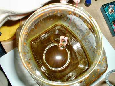
After about half an hour or more, the etching process was complete. It took a while because I am assuming my etchant is running low.
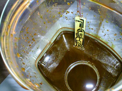
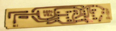
You can see the difference in the colour of the board now, that is because all the exposed copper has been removed by the etchant. The only bit remaining is the bit at the bottom edge. The reason for this is the nature of the ferric chloride solution deposit iron as it removes the copper. That means I have a layer of iron at the bottom of this jar which was preventing the copper from being etched. This bottom area of the PCB was the only part resting on the bottom of the jar as I suspended the rest of the board by using cotton thread, which you can see (it is red). This is a good idea to avoid messy retreive of the board after etching is complete.
Once the PCB was cleaned and the etch resist pen was removed, the result is below:
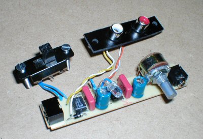
While I waited for the etching to be done, I started work on drilling the box. I got a total of two holes done as I found I spent a lot of time modifying the phono sockets so they would fit in the box snugly. With the phono sockets nearly in place (need to be screwed down yet) and the board soldered up with components, here is the two together:
The board looks rather nice from above and you can see that the whole design has minimal wire use, 6 in total. It's easy to spot that there are two TDA7052 amp circuits there by the simple fact that the middle part of the board is similar to the left. Differences being that there is an LED and its resistor in the middle, and on the far left is the DC power socket and protection diode. The switch is a simple slide switch that cuts of the negative voltage. You can also see from the picture how I had to cut and file the phono socket board to get it to fit in the box.
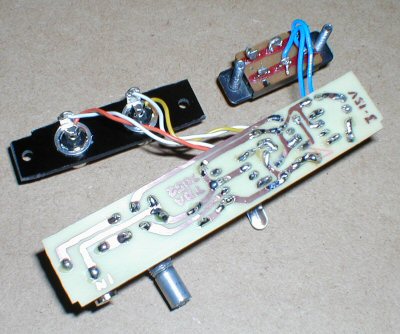
The back shows the neat soldering job and how the wires are connected to the power switch and the phono sockets. It's very simple hock ups indeed.
On testing, so far, the amplifier worked with both channels perfectly first time. Absolutely no mishaps at all, which is always makes a guy happy :-D
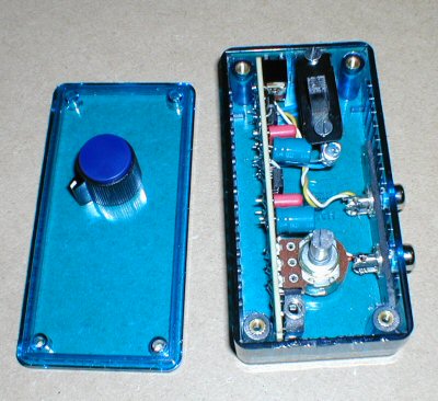
Below are 2 views of the amplifier complete, plugged in and working at the time of the photos.
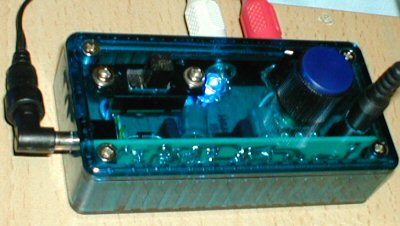
You can see that it is actually a small and neat little design. Power input is on the side and a rather large slide switch is mounted on the top. Next to that is a lovely blue LED and then there is the volume control followed by the 3.5mm jack input socket. On the side above the volume control is the two phono sockets as shown in previous pictures.
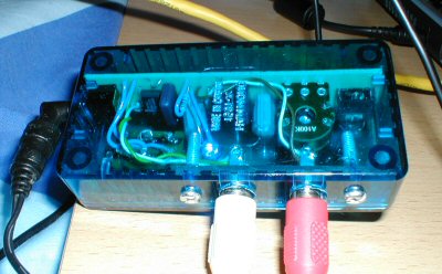
From the bottom, there is a clearer view of the circuitry that makes it all work :)
Plugged into a decent set of stereo speakers, it shows promising capabilities with good tonal response. There is a little bit of hum unfortunately, but I am blaming that on the £1 multi-voltage PSU from the boot sale. Otherwise, its application is already in use as a better music system for my laptop. I shall hook up the surround sound decoder another time.